Reproduction forbidden without Fibocom Wireless Inc. written authorization - All Rights Reserved.
FIBOCOM SU806 Series Hardware Guide
Page 45 of 91
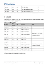
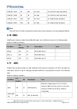
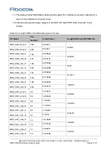
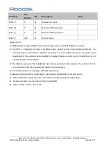
Pin Name
Pin
Number
I/O
Description
Note
MIPI_DSI0_LN1_P
57
AO
MIPI display serial interface Lane 1+
-
MIPI_DSI0_LN2_N
58
AO
MIPI display serial interface Lane 2-
-
MIPI_DSI0_LN2_P
59
AO
MIPI display serial interface Lane 2+
-
MIPI_DSI0_LN3_N
60
AO
MIPI display serial interface Lane 3 -
-
MIPI_DSI0_LN3_P
61
AO
MIPI display serial interface Lane 3 + -
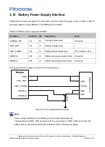
LCD_RST
49
DO
LCD reset
-
PWM
29
DO
LCD backlight PWM
-
LCD_TE
50
DI
LCD tearing effect
Keep floating if
unused
GPIO_25
190
DO
LCD backlight enable
-
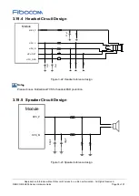
The reference design of LCD interface circuit is shown as follows:
Module
MIPI_DSI_LN3_P
LCD_RST
MIPI_DSI_LN3_N
MIPI_DSI_LN2_P
MIPI_DSI_LN2_N
MIPI_DSI_LN1_P
MIPI_DSI_LN1_N
MIPI_DSI_CLK_P
MIPI_DSI_CLK_N
MIPI_DSI_LN0_P
MIPI_DSI_LN0_N
C
AM
C
onn
e
ct
or
MIPI_D3P
LED_K1_N
MIPI_D3N
MIPI_D2P
MIPI_D2N
MIPI_D1P
MIPI_CLKP
MIPI_CLKN
LC
M
C
on
ne
ct
or
LED_K2_N
LCD_RST_N
LCDTE
MIPI_D1N
MIPI_D0P
MIPI_D0N
VDD2V8
LED_A2_P
LED_A1_P
PM_2V85
VDD1V85
PM_1V8
LCD_TE
DCDC
LCD_BL_EN
LCD_PWM
100
nF
1
0
0
nF
100
nF
2
.2
uF
GPIO
LCD_ID
VABT
EMI
EMI
EMI
EMI
EMI
Figure 3-15 LCM reference design

