Reproduction forbidden without Fibocom Wireless Inc. written authorization - All Rights Reserved.
FIBOCOM SU806 Series Hardware Guide
Page 42 of 91
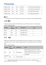
CAM_I2C_SCL0
83
DO
I2C clock
For rear/front camera by default
CAM_I2C_SDA0
84
I/O
I2C data
For rear/front camera by default
CAM_I2C_SCL1
239
DO
I2C clock
For depth camera by default
CAM_I2C_SDA1
240
I/O
I2C data
For depth camera by default
Note:
When I2C has more than one peripheral, please ensure the uniqueness of every peripheral address.
3.10 RBG
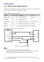
SU806 series module provides three RGB LED inputs, its pin definition is shown in the following table:
Table 3-14 RGB pin definition
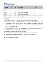
Pin Name
Pin
Number
I/O
Description
Note
LED_B
194
AI
RGB LED input 2
-
LED_G
195
AI
RGB LED input 1
-
LED_R
196
AI
RGB LED input 0
-
3.11 ADC
SU806 series module provides one ADC interface and its maximum resolution is 12 bits. It provides one
ADC4_BAT_ID which is use for charging temperature detection. Its pin definition is shown in the following
table:
Table 3-15 ADC pin definition
Pin Name
Pin
Number
I/O
Description
Note
ADC
128
AI
ADC detection
Detection voltage range is 0.1V~1.2V with
maximum 50mV accuracy and 0.1V~3.0V with
maximum 150mV test accuracy, software
configurable
ADC4_BAT
_ID
260
AI
BAT_ID detection
-

