

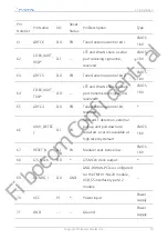

5.2. Control Interface
The module has three control signals for power on/off and reset of the module. The pins
are defined in the following table.
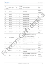
Table 15. Control signal
Pin Name
I/O
Pin
Number
Description
RESET_N
DI
1
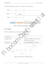
In the power-on state, pull down RESET_N for 0.5s
to 3s, and then release it. The module is reset. The
chip is internally pulled up.
FULL_CARD_
POWER_OFF
#(3.3V/1.8V)
DI
4
Module on/off signal, pull up to power on, and pull
down to power off. In the power-off state, pull up
the FCP# for more than 1.2s. The module is
powered on.
5.2.1. Power on/off
5.2.1.1. Power on
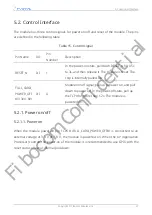
When the module power-on pin FCPO# (FULL_CARD_POWER_OFF#) is connected to an
external voltage of 3.3 V or 1.8 V, the module is powered on. When the AP (Application
Processor) controls the power-on of the module, it is recommended to use GPIO with the
reset status of low or internal pull-down.
5. Functional Interface
Copyright © Fibocom Wireless Inc.
27
Fibocom Confidential


