T2-3-20
EX355
ELECTRICAL SYSTEM
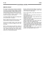
ENGINE AND PUMP CONTROL CIRCUIT
The main controller (MC) monitors all digging func-
tions, travel functions, and hydraulic pump functions
Further the main controller stores possible malfunc-
tion conditions of hydraulic and electrical system
generating faults codes that can be detected from
the diagnostic instrument (Dr.EX).
The main controller(MC) receives as input signals:
- from panel switch the signals related to the travel
speed, the auto idle position and work mode selec-
tion;
- from the R.H. control lever hand grip the input signal
of power boost;
- from engine speed control dial panel the engine
speed signal and mode switches E and HP signals.
To provide the required functions, the main controller
(MC), compares these input signals with instant con-
ditions detect from various pressure switches and
sensors and provide output signals for the engine
speed control (by means of the operation of EC
motor), and for the pump control circuit (by means of
solenoid valves operation).
•
Engine speed control circuit
The engine speed control circuit consists of engine
control dial, E and HP mode switches Auto Idle
switch, N sensor and EC motor and angle sensor
assembly.
The engine control dial adjusts the engine revolu-
tions independently of positions of E mode, HP
mode switches.
The engine control dial sends an electrical signal to
the main controller proportionally to the engine
control dial angle. (This signal can be detected from
Dr.EX with monitor function by selecting:
Target
engine speed).
The N sensor supply signal to the main controller
indicating the engine speed. (This signal can be
detected from Dr.EX with monitor function by se-
lecting:
Actual engine speed).
In order to change the engine speed, the main
controller sends signals to the EC motor, that re-
volves and controls the governor lever. (This signal
can be detected from Dr.EX with monitor function by
selecting:
EC motor position).
The EC angle sensor detects the position of EC
motor and supplies signals to the main controller to
indicate the position of the governor lever. (This
signal can be detected from Dr.EX with monitor
function by selecting:
EC angle).
The main controller (MC) compares and processes
the input signals and if the engine requires engine
speed changes, it supplies power to the EC motor
in order to change the position of governor lever.
Содержание EX355 Tier2
Страница 22: ...T1 2 10 EX355 COMPONENT LAYOUT NOTES ...
Страница 37: ...T2 1 14 EX355 CONTROL SYSTEM NOTES ...
Страница 47: ...T2 2 10 EX355 HYDRAULIC SYSTEM NOTES ...
Страница 73: ...T2 3 26 EX355 ELECTRICAL SYSTEM NOTES ...
Страница 86: ...T3 1 12 EX355 PUMP DEVICE NOTES ...
Страница 94: ...T3 2 8 EX355 SWING DEVICE NOTES ...
Страница 113: ...EX355 T3 3 19 CONTROL VALVE Port b Check Valve 2 Port a Boom Cylinder Port c Check Valve 1 SM6068 ...
Страница 134: ...T3 4 10 EX355 PILOT VALVE NOTES ...
Страница 146: ...T3 5 12 EX355 TRAVEL DEVICE NOTES ...
Страница 156: ...T3 7 4 EX355 OTHER COMPONENTS Undercarriage NOTES ...
Страница 195: ...T4 2 6 EX355 STANDARD NOTES ...
Страница 199: ...T4 3 4 EX355 ENGINE TEST NOTES ...
Страница 215: ...T4 4 16 EX355 EXCAVATOR TEST NOTES ...
Страница 237: ...T4 5 22 EX355 COMPONENT TEST NOTES ...
Страница 265: ...T5 2 12 EX355 COMPONENT LAYOUT NOTES ...
Страница 325: ...T5 4 52 EX355 TROUBLESHOOTING B ...
Страница 372: ...EX355 T5 6 9 ELECTRICAL SYSTEM INSPECTION ...
Страница 380: ...EX355 T5 6 17 ELECTRICAL SYSTEM INSPECTION 5 Identify the relay on the terminal board 6 Replace the relay SM5622 ...
Страница 385: ...T5 6 22 EX355 ELECTRICAL SYSTEM INSPECTION NOTE ...
Страница 425: ...W1 1 4 EX355 PRECAUTIONS FOR DISASSEMBLY AND ASSEMBLY NOTES ...
Страница 450: ...W2 3 8 EX355 MAIN FRAME NOTES ...
Страница 454: ...W2 4 4 EX355 PUMP DEVICE SM5510 ...
Страница 456: ...W2 4 6 EX355 PUMP DEVICE SM5510 ...
Страница 458: ...W2 4 8 EX355 PUMP DEVICE ASSEMBLE PUMP DEVICE SM6205 SM6206 ...
Страница 460: ...W2 4 10 EX355 PUMP DEVICE SM6205 SM6206 ...
Страница 462: ...W2 4 12 EX355 PUMP DEVICE SM6205 SM6206 ...
Страница 464: ...W2 4 14 EX355 PUMP DEVICE SM6205 SM6206 ...
Страница 468: ...W2 4 18 EX355 PUMP DEVICE SM6210 ...
Страница 470: ...W2 4 20 EX355 PUMP DEVICE SM6210 ...
Страница 472: ...W2 4 22 EX355 PUMP DEVICE SM6210 ...
Страница 474: ...W2 4 24 EX355 PUMP DEVICE SM5511 SM6219 ASSEMBLE MAIN PUMP ...
Страница 476: ...W2 4 26 EX355 PUMP DEVICE SM5511 SM6219 ...
Страница 478: ...W2 4 28 EX355 PUMP DEVICE SM5511 SM6219 ...
Страница 480: ...W2 4 30 EX355 PUMP DEVICE SM5511 SM6219 ...
Страница 482: ...W2 4 32 EX355 PUMP DEVICE SM5511 SM6219 ...
Страница 484: ...W2 4 34 EX355 PUMP DEVICE SM5511 SM6219 ...
Страница 486: ...W2 4 36 EX355 PUMP DEVICE SM5511 SM6219 ...
Страница 498: ...W2 4 48 EX355 PUMP DEVICE NOTES ...
Страница 532: ...W2 5 34 EX355 CONTROL VALVE NOTES ...
Страница 540: ...W2 6 8 EX355 SWING DEVICE SM6277 31 18 17 20 19 21 3 24 27 25 26 10 ...
Страница 542: ...W2 6 10 EX355 SWING DEVICE SM6277 31 19 2 1 23 22 ...
Страница 566: ...W2 7 12 EX355 PILOT VALVE 11 19 17 18 1 2 3 8 13 14 16 15 SM1114 ...
Страница 572: ...W2 7 18 EX355 PILOT VALVE 8 6 7 1 3 4 5 9 21 2 SM1119 ...
Страница 586: ...W2 7 32 EX355 PILOT VALVE NOTES ...
Страница 592: ...W2 8 6 EX355 PILOT SHUT OFF VALVE NOTES ...
Страница 602: ...W2 10 6 EX355 SOLENOID VALVE UNIT NOTES ...
Страница 621: ...W3 2 10 EX355 TRAVEL DEVICE SM5108 44 8 13 12 1 45 46 28 27 25 26 24 36 38 30 31 32 ...
Страница 623: ...W3 2 12 EX355 TRAVEL DEVICE 29 SM5108 42 44 8 13 12 1 2 23 8 9 10 43 17 11 15 14 41 40 21 20 22 18 19 16 30 31 32 ...
Страница 627: ...W3 2 16 EX355 TRAVEL DEVICE SM5502 3 4 5 20 7 8 9 10 12 14 13 16 11 6 ...
Страница 633: ...W3 2 22 EX355 TRAVEL DEVICE SM5111 Cross Section A 36 38 40 24 23 34 35 28 37 39 22 21 19 30 29 31 33 ...
Страница 643: ...W3 2 32 EX355 TRAVEL DEVICE NOTES ...
Страница 651: ...W3 3 8 EX355 CENTER JOINT NOTES ...
Страница 655: ...W3 4 4 EX355 TRACK ADJUSTER 8 14 13 11 17 12 SM6284 ...
Страница 657: ...W3 4 6 EX355 TRACK ADJUSTER 3 4 8 10 16 15 14 SM6284 ...
Страница 659: ...W3 4 8 EX355 TRACK ADJUSTER 3 6 4 8 10 9 SM6284 18 ...
Страница 667: ...W3 4 16 EX355 TRACK ADJUSTER NOTES ...
Страница 671: ...W3 5 4 EX355 FRONT IDLER 1 SM6290 2 4 3 5 6 8 12 7 6 3 4 1 2 9 10 11 ...
Страница 682: ...EX355 W3 6 7 UPPER AND LOWER ROLLER DISASSEMBLE UPPER ROLLER NOTE Replace the upper roller as an assembly SM1241 ...
Страница 689: ...W3 6 14 EX355 UPPER AND LOWER ROLLER NOTES ...
Страница 708: ...W4 1 10 EX355 FRONT ATTACHMENT NOTES ...
Страница 716: ...W4 1 18 EX355 FRONT ATTACHMENT NOTES ...
Страница 744: ...W4 2 28 EX355 CYLINDERS NOTES ...
Страница 763: ...EX355 W5 1 17 GENERAL INFORMATION Oil Pan N m kgf m Ib ft SM7010 ...
Страница 765: ...EX355 W5 1 19 GENERAL INFORMATION Water Pump N m kgf m Ib ft SM7012 ...
Страница 815: ...EX355 W5 3 35 ENGINE OVERHAUL Disassembly SM7093 1 Camshaft gear 2 Knock pin 3 Camshaft ...
Страница 855: ...EX355 W5 3 75 ENGINE OVERHAUL OIL PAN Removal 1 Clip 4 Oil strainer 2 Oil pan 5 Gasket 3 Gasket SM7187 ...
Страница 861: ...EX355 W5 3 81 ENGINE OVERHAUL PISTON Removal 1 Bearing cap 3 Bearings 2 Bolt 4 Piston with connecting rod SM7199 ...
Страница 883: ...EX355 W5 3 103 ENGINE OVERHAUL Reassembly 1 Crankshaft 3 Crankshaft gear 2 Pin SM7239 ...
Страница 894: ...W5 3 114 EX355 ENGINE OVERHAUL NOTE ...
Страница 908: ...W5 5 2 EX355 ENGINE COOLING SM7287 THERMOSTAT Disassembly 1 Water outlet pipe 3 Gaskets 2 Thermostats ...
Страница 918: ...W5 6 4 EX355 ENGINE FUEL FUEL FILTER Disassembly 1 Fuel filter 3 Fuel filter body 2 Overflow valve SM7305 ...
Страница 938: ...W5 7 6 EX355 ENGINE INDUCTION NOTE ...
Страница 958: ...W5 8 20 EX355 STARTING AND CHARGING NOTE ...


