background image

EX355

W2-7-1

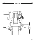
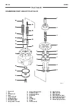
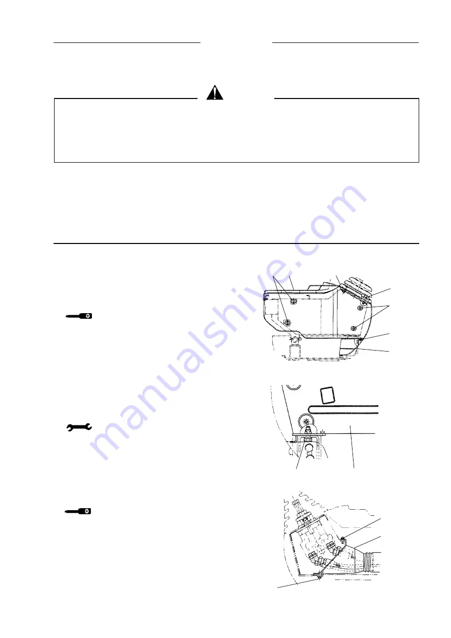
PILOT VALVE

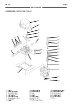
1      2                    3

4

5

6

7

SM1105

10

11

12

SM1107

8                          9

SM1106

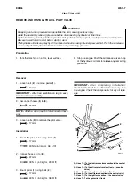
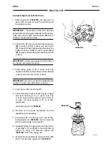
REMOVE AND INSTALL RIGHT PILOT VALVE

Preparation

1. Park  the  machine  on  a  firm,  level  surface.

2. Stop the engine. Push the air release valve on top

of the hydraulic oil tank to release any remaining
pressure.

Removal

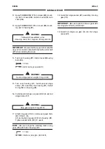
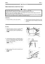
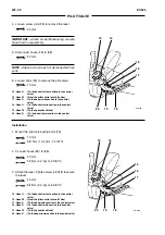
1. Loosen screws (

6

) (2 used), (

1

) (2 used) and (

5

)

(2 used) to remove cover (

7

) and frame (

2

).

Loosen screws (

4

) (4 used) to dislocate boot (

3

).

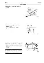
2. Confirm that the console is in the forefront posi-

tion. If not, position the console in the forefront
position. Loosen bolts (

8

) (2 used) to disconnect

the joints. Raise stand (

9

).

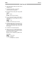
: 17 mm

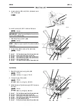
3. Remove screws (

10

) and (

12

). Dislocate cover

(

11

) to the right.

  WARNING

Escaping fluid under pressure can penetrate the skin, causing serious injury.
Avoid the hazard by relieving pressure before disconnecting hydraulic or other lines.
Hydraulic oil may be hot just after operation. Hot hydraulic oil may spout, possibly causing severe burns.
Be sure to wait for oil to cool before starting work.
The hydraulic oil tank cap may fly off if removed without releasing internal pressure first. Push the air release
valve on top of the hydraulic oil tank to release any remaining pressure.

Содержание EX355 Tier2

Страница 1: ...EX355 Tier2 TECHNICAL MANUAL OPERATIONAL PRINCIPLE TECHNICAL MANUAL TROUBLESHOOTING WORKSHOP MANUAL WORKSHOP MANUAL ENGINE ...

Страница 2: ...ion July 2002 EXCAVATOR TECHNICAL MANUAL OPERATIONAL PRINCIPLE Tier 2 All information illustrations and specifications in this manual are based on the latest product information available at the time of publication The right is reserved to make changes at any time without notice ...

Страница 3: ... The complete service manual consists of three books Technical Manual Operational Principle TechnicalManual Troubleshooting WorkshopManual The Technical Manual Operational Principle in cludes the technical information concerning the operation of main devices and systems The Technical Manual Troubleshooting includes the technical information needed for operational performancetests andtroubleshootin...

Страница 4: ...er if exist Sectionnumber T TechnicalManual W WorkshopManual SYMBOLS In this manual the following safety alert symbol and signal words are used to alert the reader to the potential for personal injury or machine damage This is the safety alert symbol When you see this symbol be alert to the potential for personal injury Never fail to follow the safety instructions prescribed along with the safety ...

Страница 5: ... Travel Device Group 6 Other components Upperstructure Group 7 Other components Undercarriage TECHNICAL MANUAL EX355 OPERATIONAL PRINCIPLE SECTION AND GROUP CONTENTS Section 1 GENERAL Group 1 Specifications Group 2 Component Layout Section 2 SYSTEM Group 1 Control System Group 2 Hydraulic System Group 3 Electrical System ...

Страница 6: ... 1 3 Excavator performance T1 1 4 Engine T1 1 4 Engine accessory T1 1 5 Hydraulic Devices T1 1 5 Electrical Equipment T1 1 6 Group 2 Component layout Main components T1 2 1 Electrical system Overall system T1 2 2 Electrical system Cab T1 2 3 Electrical system Monitor and Switch panels T1 2 5 Electrical system Batteries compartment T1 2 6 Electrical system Fuses T1 2 7 Other components T1 2 8 ...

Страница 7: ...oewidth mm 600 700 800 900 600 700 800 900 N Maximum width mm 3000 3100 3200 3300 3190 3290 3390 3490 Working weight kg 33400 33825 34250 34675 33650 34075 34500 34925 Spec Ground Press bar 0 66 0 57 0 50 0 45 0 66 0 57 0 50 0 45 EX355 EL EX355 LC OM0554 DIGGING DATA 6400 mm Boom Arm mm 2300 2650 3190 3990 A mm 103201058011100 11870 A mm 101001036010900 11680 B mm 6490 6830 7360 8160 B mm 6290 665...

Страница 8: ...adius These dimensions without bucket will be F 3485 E 10640 M Trackshoewidth mm 600 700 800 900 N Maximumwidth mm 3000 3100 3200 3300 Workingweight kg 34000 34425 34850 35275 Spec Ground Press bar 0 67 0 58 0 51 0 46 EX355BEH OM0554 DIGGINGDATA 5775 mm Boom Arm mm 2070 A mm 9360 A mm 9120 B mm 5640 B mm 5400 C mm 9080 D mm 6400 E mm 4200 E OM0660 G D D C A B F H I L M N ...

Страница 9: ...ackshoewidth mm 600 700 800 900 600 700 800 900 N Maximumwidth mm 3000 3100 3200 3300 3190 3290 3390 3490 Workingweight kg 34000 34425 34850 35275 34250 34675 35100 35525 Spec Ground Press bar 0 67 0 58 0 51 0 46 0 67 0 58 0 51 0 46 EX355 EL EX355 LC DIGGINGDATA 3400 mm Boom Arm mm 2300 2650 3190 3990 A mm 10430 1072011260 12040 A mm 10210 1051011060 11850 B mm 6010 6320 6870 7660 B mm 5900 6220 6...

Страница 10: ... Clockwise view from fan side COOLINGSYSTEM Cooling fan Dia 850 mm 6 blades draw in type Fan pulley ratio Engine rpm x 0 8 Thermostat Cracking temp 82 C 180 F under atmospheric pressure Full open Stroke 10 mm or larger temp 95 C 203 F Water pump Centrifugal type belt driven LUBRICATIONSYSTEM Lubrication pump type Gearpump Oil filter Full flow paper element type with bypass function Oil cooler Wate...

Страница 11: ...0 L min Overload relief pressure 33 3 MPa 340 kgf cm2 50 L min Boom raise lower Arm roll in Bucket roll in 35 3 MPa 360 kgf cm2 50 L min Arm roll out Bucket roll out SWING DEVICE Type Two stageplanetaryreductiontype SWINGMOTOR Model M2X210CHB Type Swash plate type fixed displacement plunger motor SWING BRAKE VALVE Type Non counter balance valve type Relief pressure 28 4 MPa 290 kgf cm2 236 L min S...

Страница 12: ...P04S 040 101 TRAVEL PILOT VALVE Model HVP05D 040 101 SOLENOID VALVE UNIT Functions SC Armregenerativecontrol SD Speed sensing control SG Power boost control SI Travelmotorswashanglecontrol OIL COOLER BYPASS CHECK VALVE Crackingpressure 392 KPa 4 kgf cm2 at 5 L min ELECTRICAL EQUIPMENT BATTERY RELAY Voltage Current 24V 100A STARTER RELAY Voltage 24V GLOWRELAY Voltage 24V HORN Specifications 24V 1 5...

Страница 13: ...t 5 Swing Bearing 6 Swing Device 7 Fuel Tank 8 Hydraulic Oil Tank 9 Control Valve 10 Pilot Filter Pilot Relief Valve 11 Pump Device 12 Engine 13 Radiator 14 Oil Cooler 15 Intercooler 16 Battery 17 Travel Device 18 Shockless Valve 19 Pilot Shut Off Valve 20 Travel Pilot Valve 21 Front Swing Pilot Valve SM5601 ...

Страница 14: ...ol Side 14 EC Motor 15 EC Sensor 16 Pump Delivery Pressure Sensor 1 17 Pump Delivery Pressure Sensor 2 18 N Engine Speed Sensor 19 Engine Oil Pressure Switch 20 Coolant Temperature Switch Engine Preheat Circuit 21 Engine Oil Level Switch on oil pan 22 Overheat Switch 23 Coolant Temperature Sensor 24 Battery Relay 25 Coolant Level Switch 26 Battery 27 Starter Relay 28 Air Cleaner Restriction Switch...

Страница 15: ... Q O S controller 11 Load momentum alarm buzzer provision 12 Load momentum alarm relay provision 13 Breaker relay R2 variant provision 14 R H Rotation bucket relay R1 variant provision 15 L H Rotation bucket relay R3 variant provision 16 Cab light relay R5 17 Rear cab light relay R6 18 A B K junction connector 19 C D juncton connector 20 E F junction connector 21 G H junction connector 22 Dr EX co...

Страница 16: ...ab harness 4 Connectors not used 5 Windshield wiper controller 6 1 connector for breaker switch 2 connector for cab light switch 3 connector for bucket rotation 4 connector for load momentum alarm switch 5 connector for rear cab light SM5604 ELECTRICAL SYSTEM Cab 7 Connector not used 8 Connector 3 4 5 6 7 8 1 2 ...

Страница 17: ...ndicator 16 Air Filter Restriction Indicator 17 Fuel Level Indicator 18 Overheat Indicator 19 Alternator Indicator 20 Engine Oil Pressure Indicator 21 Engine Oil Level Indicator 22 Coolant Level Indicator 23 HP Mode Indicator 24 Coolant Temperature Gauge 25 Work Light Switch 26 Wiper Switch 27 Travel Mode Switch 28 Work Mode Switch 29 Buzzer Stop Switch 30 Auto Idle Switch 31 Washer Switch 32 Leve...

Страница 18: ...AL SYSTEM Batteries compartment 1 Battery relay 2 Fuse link Box B Fuse 3 60A 3 Fuse link Box A Fuse 1 40A Fuse 2 40A 4 Connection box 5 Safety relay 6 Engine coolant level switch 7 Ground joint connector 8 Glow relay SM5605 8 1 2 3 4 5 6 7 ...

Страница 19: ...IGHT power supply 6 HAMMER Breaker 10 7 ROTARY Bucket 10 BUCKET rotation 8 SOLENOID Solenoid valve 5 power supply 9 SW BOX Switches 5 panel 10 HEATING Heating seat 10 SEAT 11 WIPER Windshield wiper 10 12 HEATER Heater 20 13 LIGHT Light 15 14 CAB LIGHT Cab light 15 15 RADIO Radio 5 16 LIGHTER Cigar light 15 17 HORN Horn 10 18 GLOW Glow relay 5 RELAY power supply 19 POWER ON Power supply on 5 20 AIR...

Страница 20: ... Pump 3 Regulator Pump 1 4 Pump 2 5 Pump Delivery Pressure Sensor Pump 2 6 Pump 1 SM6004 Pump device Travel device Pilot filter 7 Pump Delivery Pressure Sensor Pump 1 8 N Engine Speed Sensor 9 Counterbalance Valve 10 Travel Relief Valve 11 Pilot filter 12 Pilot relief valve ...

Страница 21: ...ck Valve 5 Check Valve 6 Pilot Pressure Switch Boom Raise Swing Device Shockless Valve Solenoid Valve Unit 1 T157 01 01 011 T157 07 03 018 T157 01 01 012 7 Check Valve 8 Solenoid Valve Unit SC 9 Solenoid Valve Unit SD 10 Solenoid Valve Unit SI 11 Solenoid Valve Unit SG SM0626 SM6005 SM5606 5 6 2 7 4 3 11 10 9 8 ...

Страница 22: ...T1 2 10 EX355 COMPONENT LAYOUT NOTES ...

Страница 23: ...ion T2 2 4 Combined operation T2 2 6 Group 3 Electrical system Outline T2 3 1 Electric power circuit Key Switch OFF T2 3 2 Bulb Check Circuit Key Switch ON T2 3 4 Accessory Circuit Key Switch ACC T2 3 6 Preheat Circuit Key Switch ON or START T2 3 8 Starting Circuit Key Switch START T2 3 10 Charging Circuit Key Switch ON T2 3 12 Surge Voltage Prevention Circuit T2 3 16 Engine Stop Circuit Key Switc...

Страница 24: ...in main controller MC is pro vided to control machine operation Electronic sens ing signals from the engine control dial various sen sors and switches are sent to the MC After processing the sensing signals in the logic circuits the MC sends out the control signals to the EC motor and solenoid valve unit to control the engine pump and valve operations Sensing signals Input signals EC sensor Engine...

Страница 25: ...control Auto Idle control Engine learning control Pilot pressure sensor Arm Roll in Pressure switch Travel Pressure switch Front Pump delivery pressure sensor Pump 1 2 ENGINE M HP mode switch E mode switch A I H P E P V SM0101 Layout of engine control system Learning switch MC EC sensor EC motor Engine control dial Key switch Auto Idle switch ...

Страница 26: ...g the governor lever to move to control engine speed The EC sensor feedbacks the position of the EC motor to the MC This confirms that the EC motor moves according to commands from the MC M ENGINE P V A I H P E Stop Full SM6007 NOTE Normally the governor lever does not come intocontactwiththefullsidestoppereveniftheengine control dial is turned to the full speed position Refer to HP Mode Control E...

Страница 27: ...500 min 1 or faster HP Mode Switch ON Operation Arm Roll In Average Delivery Pressures of Pump 1 and 2 Higher Range NOTE The engine governor stopper position is adjusted in accordance with the HP mode operation Therefore the governor lever does not come into contact with the stopper in the Normal Control mode SM6008 Pilot pressure sensor Arm Roll in Pump delivery pressure sensor M ENGINE Stop Full...

Страница 28: ...r to run the engine in the speed range slower than normal operation in proportion to the engine control dial set angle M ENGINE E Engine control dial A I H P P V E mode switch SM0106 When the E mode switch is not depressed Engine speed Slow Idle Fast Idle Max Speed SM0105 Governor lever EC motor MC When the E mode switch is depressed Fast Idle Max Speed Slow Idle ...

Страница 29: ... auto idle switch is ON and all control levers are kept in neutral the pressure switches for travel and front operations are off for more than four seconds the MC instructs the EC motor to reduce the engine speed to the auto idle speed M EC motor ENGINE P V A I H P E Pressure switch Travel SM0107 Pressure switch Front Governor lever MC Auto Idle switch Engine control dial ...

Страница 30: ...the stopper positions for the FULL and STOP operation The signals corre sponding to each stopper position are sent to the MC from the EC sensor and the MC stores the data IMPORTANT Besuretooperatetheenginelearning control system after replacing the engine engine control cable EC motor or MC The procedure is listed in the Technical Manual Troubleshooting on page T5 4 60 NOTE The replacement of batt...

Страница 31: ...o the control signals from the MC the solenoid valve unit SD supplies pilot oil pressure to the pump regulators to control the pump flow rate When poor quality fuel is used or if the machine is operated at high altitudes the engine output torque may decrease causing the engine to run slower than the target speed As the MC in the speed sensing control system instructs the solenoid valve unit SD to ...

Страница 32: ...t pressure Sensor Arm Roll In Power Boost Switch Travel Mode Switch Travel Motor Swash Angle Control Servo Piston Pressure Switch Front Pressure Switch Travel Pump Control Pressure Sensor 5 Spool Side Arm Regenerative Valve Main Relief valve To MC To MC Pump Delivery Pressure Sensor Pump Control Pressure Sensor 4 Spool Side From Pump Control Pressure Sensor MC Solenoid Valve Unit ...

Страница 33: ...ef pressure Operation When the power boost switch is turned ON the MC magnetizes solenoid valve unit SG for 8 seconds When magnetized solenoid valve unit SG supplies pilot oil pressure to the relief valve to increase the relief set pressure Solenoid Valve Unit SM6011 Main Relief Valve MC Arm Cylinder Power Boost Switch ...

Страница 34: ...urn circuit to the hydraulic oil tank from the arm cylinder rod side Thereby the return oil from the arm cylinder rod side SM6012 iscombinedwiththepumpdeliveryoilandsuppliedto the arm cylinder bottom side increasing the arm roll in speed and preventing arm roll in hesitation Operation Conditions PumpDeliveryPressureSensor Pump2 Delivery pressure from pump 2 is low requiring less arm operating forc...

Страница 35: ... SM6013 Operation Conditions Pressure Switch Travel ON Pressure Switch Front OFF Pump Delivery Pressure Sensors Pump 1 and 2 Pump delivery pressure is low Pump Displacement Target Angle controlled by the MC according to signals from sensors and switches Large NOTE Even if the track is revolved with the track raised one side pump displacement target angle remains small so that the travel motor spee...

Страница 36: ...Refer to T2 1 11 PRECISION MODE In all work modes engine speed is reduced to 70 of the full speed set when the engine control dial is placed in the full position The main relief pressure is increased in boom raise operation Refer to T2 1 10 ATTACHMENT MODE Only when the attachment option kit is installed this function works In proportion to the auxiliary pilot valve lever stroke the engine speed i...

Страница 37: ...T2 1 14 EX355 CONTROL SYSTEM NOTES ...

Страница 38: ... the oil cooler Whenoiltemperatureislow viscosityishigh return oil flowing through the oil cooler will be ham pered because of the increased flow resistance in the oil cooler If that happens the bypass check valve opens allowing the return oil to directly flow back to the hydraulic oil tank SM3005 Full flow filter Suction filter Hydraulic oil tank Pressure oil Return oil Oil cooler Engine Bypass c...

Страница 39: ...group in the COMPO NENT OPERATION section This circuit changes the arm regenerative valve main relief valve setting pressure power boost and travel motor swash angle control servo piston by the solenoid valve unit SC SG SI Swing Parking Brake Release Circuit Refer to the Swing Device group in the COMPO NENT OPERATION section When the pilot signal circuit Front Swing closes this circuit releases th...

Страница 40: ...lease Circuit Pilot Shut off Valve Manifold for Shockless Valves Pressure Sensor and for Pressure Switch Hydraulic Oil Tank Suction Filter Swing Motor Pilot Operating Circuit Pilot Pump Main Pump Regulator Pilot Filter Pilot Relief Valve Travel Motor Main Relief Valve Positioning Pilot Valve Travel Motor Arm Regenerative Valve 5 spool Side Pump Control Valve 4 spool Side Pump Control Valve Hydraul...

Страница 41: ...vel R Bucket Boom 1 and Arm 2 in the 4 spool section in the control valve Pressure oil from pump 2 flows to the spools Swing Arm 1 Boom 2 Auxiliary and Travel L in the 5 spool section in the control valve When arm roll in roll out or boom raise levers are operated pressure oil from both pumps is combined and flows together into the respective cylinder NOTE The boom lower operation is actauted only...

Страница 42: ...EM SM6015A Left Travel Motor Right Travel Motor Travel R Bucket Bucket Cylinder Boom Cylinder Boom 1 Arm 2 Hydraulic Oil Tank 4 Spool Side Pump 2 Pump 1 5 Spool Side Swing Motor Swing Boom 2 Arm Cylinder Arm 1 Auxiliary Travel L ...

Страница 43: ...s in the control valve Then pressure oil from pump 1 flows from boom 1 spool via the parallel passage into the boom cylinder to raise the boom Pressure oil from pump 2 flows from swing spool into the swing motor to swing the upperstructure At the same time pressure oil flows from boom 2 spool via the parallel passage into the boom cylinder and joins pressure oil from pump 1 to raise the boom ...

Страница 44: ...EX355 T2 2 7 HYDRAULIC SYSTEM SM6016 Boom Cylinder Boom 1 Pump 2 Pump 1 Swing Motor Swing Boom 2 Parallel Passage Parallel Passage ...

Страница 45: ...rcuit rises due to arm spool movement shift ing flow combiner valve Then pressure oil from pump 1 flows into the right travel motor via the travel R spool actuating it At the same time pressure oil flows from the flow combiner valve into the left travel motor via the travel L spool actuating it For this reason the machine can travel straight Pressure oil from pump 2 flows into the arm cylinder via...

Страница 46: ...EX355 T2 2 9 HYDRAULIC SYSTEM SM6017 Flow Combiner Valve Travel R Arm 2 Pump 1 Pump 2 Arm Cylinder Left Travel Motor From Pilot Pump Right Travel Motor Arm 1 Travel L Front Att Pilot Signal Circuit ...

Страница 47: ...T2 2 10 EX355 HYDRAULIC SYSTEM NOTES ...

Страница 48: ...nd Fu sible links Battery Relay Bulb Check Circuit Checksforblownwarninglightsandindicatorbulbs on monitor Accessory Circuit Works with the key switch placed in the ACC position Preheat Circuit Helps start the engine in cold weather Key Switch QOS Controller Glow relay Glow plugs Starting Circuit Starts the engine Key Switch Starter Starter Relay Charging Circuit Recharges batteries and supplies e...

Страница 49: ...ive terminal flows as follows with the key switch OFF Fuse link 2 40 A Glow relay Power Source Terminal 1 Radio Backup Power Source Monitor Backup Power Source Battery Terminal 2 MC Power Source Terminal 3 MC EC Motor Terminal 4 Auxiliary source relay box Fuse link 1 40 A Fuse box Relay box terminal 14 Relay R1 Anti Load Dump Terminal B Key switch ...

Страница 50: ... EC motor Auxiliary power Relay box to monitor 18 Fuse box to Monitor 43 Key switch Q O S Controller To fuel transfer pump motor opt Glow relay Fuse link Batteries Glow plugs Starter motor Safety relay to Monitor 42 Alternator Coolant temperature switch Battery relay ...

Страница 51: ...inal B connects with key switch terminals M and ACC The current from terminal M flows throught the diode D2 located inner the relay box and excites the battery relay Then the battery power is routed to the monitor through the battery relay the fuse box and the wiper box turning the warning lights and indicators on for bulb check ...

Страница 52: ...x Monitor Fuse box To motor 18 Relay box Key switch To monitor 43 QOS Controller To fuel transfer pump motor opt Coolant temperature switch Glow relay Fuse link Batteries Battery relay Starter motor Safety relay To monitor 42 Alternator Glow plugs ...

Страница 53: ... ACC When the key switch is turned to the ACC position terminal ACC is connected to terminal B in the key switch Then the battery current flows through the fuse box terminal 15 16 and 17 to each accessory circuits horn radio cigar lighter power outlet room lamp ...

Страница 54: ...EX355 T2 3 7 ELECTRICAL SYSTEM Power outlet Cigar lighter Key switch Room light Radio Horn Batteries SM5609 Fuse link To monitor 30 ...

Страница 55: ...Throught the relay box When the coolant temperature switch is OFF QOS controller allows to preheat the engine for approx 30 seconds When QOS controller terminal 4 is grounded glowplugrelaycomesON sothattheglow plugs are heated Terminal 6 of QOS controller grounds to vehicle for 8 seconds while preheat therefore glow signal is ON When preheat is not done glow signal is ON for 0 3 seconds to check t...

Страница 56: ...EX355 T2 3 9 ELECTRICAL SYSTEM To monitor 18 Monitor panel Key switch Fuse box Relay box QOS Controller Fuse link Batteries Coolant temperature switch N C 10 C Glow relay Glow plugs SM5610 ...

Страница 57: ...y switch is turned to the START position key switch terminal B and ST have conti nuityinthekeyswitch Then thecurrentflowstothe base of transistor Q2 via resistance R4 in the starter relay switching transistor Q2 ON Thereby the current flows through coil L of relay closing the circuit between starter terminals B and C Then the starter begins to rotate Once the engine is started the alternator begin...

Страница 58: ...EX355 T2 3 11 ELECTRICAL SYSTEM SM5611 To monitor 18 Key switch Fuse box Main controller MC Relay box Fuse link Batteries Starter motor Battery relay Safety relay To monitor 42 Alternator ...

Страница 59: ...ith the key switch kept ON key switch terminal B is con nected to terminals ACC and M After the engine starts the alternator begins power generation Current from terminal B on the alternator flows to the batteries through the battery relay re charging the batteries In addition this current from Alternator terminal L flows to the monitor to turn off the charge lamp ...

Страница 60: ...EX355 T2 3 13 ELECTRICAL SYSTEM Relay box Fuse box Key switch Monitor panel Starter motor Alternator Batteries Battery relay SM5612 ...

Страница 61: ...r E Accordingly fieldcoilFCisgroundedthroughtransis tor T1 At first the current does not flow to field coil FC When the rotor starts to rotate alternating voltage is generatedinstatorcoilSCduetoresidualmagnetism in the rotor Thereby the current starts to flow through field coil FC magnetizing the rotor further and increasing generating voltage As generating voltage increases the flowing current th...

Страница 62: ...turnedOFF Thereby the current flowing through field coil FC is cut causing the SC generating voltage to decrease Then when the voltage to be applied to zener diode ZDbecomeslowerthanthesetvoltageofzenerdiode ZD transistor T2 is turned OFF turning transistor T1 ONagain Thus thecurrentisallowedtoflowthrough field coil FC to increase the generating voltage by stator coil SC As this operation is repea...

Страница 63: ... failure of electrical parts and components On account of this the surge voltage prevention circuit has been provided While the batteries are being recharged the generat ing current from terminal L on the alternator is led to terminal 42 on the monitor turning the output tran sistor ON for terminal 18 on the monitor In the conditions the batteries current holds the Anti Load Dump relay R1 located ...

Страница 64: ...EX355 T2 3 17 ELECTRICAL SYSTEM SM5613 Key switch Fuse box Monitor panel Relay box Fuse link Batteries Starter motor Battery relay Safety relay Alternator ...

Страница 65: ...GINE STOP CIRCUIT Key Switch OFF When the key switch is turned from the ON position to the OFF position the signal instructing the MC that the key switch is ON is cut Then theMCmovestheECmotortothestopposition causing the engine to stop ...

Страница 66: ...EX355 T2 3 19 ELECTRICAL SYSTEM EC Sensor EC Motor Key switch To monitor 39 To Radio Fuse box Main Controller MC SM5614 Fuse link Batteries ...

Страница 67: ...consists of engine control dial E and HP mode switches Auto Idle switch N sensor and EC motor and angle sensor assembly The engine control dial adjusts the engine revolu tions independently of positions of E mode HP mode switches The engine control dial sends an electrical signal to the main controller proportionally to the engine controldialangle Thissignalcanbedetectedfrom Dr EX with monitor fun...

Страница 68: ...CAL SYSTEM to monitor panel From relay box R14 To from monitor Main Controller MC From fuse link 1 40 A From fuse link 3 60 A Fuse box Solenoid valve group Pressure switch N Sensor EC Motor Pressure sensor Key switch SM5615 ...

Страница 69: ...e and the Arm Roll in pilot pressure sensor located on shockless valve send to controller MC an electrical signal that is proportional to related pressure to be controlled The operation of each pressure sensor can be detectedfromDr EXwithmonitorfunctionbyselect ing Pump 1 or 2 Delivery pressure Pump 1 or 2 Control pressure Arm Roll in pilot pressure The Dr EX will detect the electrical signal and ...

Страница 70: ...CAL SYSTEM to monitor panel From relay box R14 To from monitor Main Controller MC From fuse link 1 40 A From fuse link 3 60 A Fuse box Solenoid valve group Pressure switch N Sensor EC Motor Pressure sensor Key switch SM5615 ...

Страница 71: ... oil level switch engine overheating switch engine oil pres sure switch fuel low level switch air filter restriction switch Q O S controller and alternator Monitor controller provides voltages to transistors if temperature pressures or levels are outside normal limits to illuminate indicator lights Engine oil level switch is closed when oil level in the oil pan is OK Coolant level switch is closed...

Страница 72: ...5 ELECTRICAL SYSTEM Alternator SM5616 Relay box Relay box Monitor panel Key switch Wiper box to wiper box From fuse link 1 40 A From fuse link 3 60 A Fuse box NOTE Shown with engine stopped and correct liquid level ...

Страница 73: ...T2 3 26 EX355 ELECTRICAL SYSTEM NOTES ...

Страница 74: ... Boom regenerative valve T3 3 18 Arm Anti drift valve Bottom side T3 3 20 Arm anti drift valve On rod side Boom anti drift valve T3 3 23 Bucket flow rate control valve T3 3 24 Travel flow rate control valve T3 3 26 Bypass shut out valve T3 3 28 NeedleValve T3 3 30 Group 4 Pilot valve Outline T3 4 1 Operation T3 4 3 Group 5 Travel device Outline T3 5 1 Travel motor T3 5 2 Parking brake T3 5 4 Trave...

Страница 75: ...main pumps and pilot pump is 0 9487 and 1 respectively The main pump is a bent axis type variable dis placement axial plunger pump The pilot pump is a gear type The engine speed sensor N sensor and pump delivery pressure sensor P sensor are pro vided to control the engine pump and valves SM6031 SM6030 SM6029 Transmission Engine Speed Sensor Main Pump 1 Main Pump 2 Pilot Pump Pump Delivery Pressure...

Страница 76: ...flow rate The pump shaft is connected to the cylinder block via seven plungers Plunger SM6032 Shaft Shaft Regulator Cylinder Block Cylinder Block Valve Plate Valve Plate SM007 When the engine rotates the shaft plungers and cylinder blocks are rotated The plungers are tilted to the shaft so that the plungers reciprocate in the cylin der block by which hydraulic oil is suctioned and dis charged ...

Страница 77: ... moving the servo piston up and down The servo piston is connected to thevalveplatebyapin Therefore astheservopiston moves the end face of the cylinder block is slide on the valve plate surface while keeping in contact with each other Minimally Tilted Position SM0009 Plunger Cylinder Block Shaft SM0008 Fully Tilted Position Servo Piston Cylinder Block Valve Plate Plunger Pin SM6032 ...

Страница 78: ... sleeveA 7 outer spring 8 andinnerspring 9 When various command signal pressures reach the regulator spools 3 and6 are moved so that the pilot oil pressure is routed to either the large diameter chamber or the small diameter chamber of servo pis ton 10 causing cylinder block 11 to change the tilt angle Thus the pump delivery flow rate is controlled 1 Spring 2 Sleeve B 3 Spool B 4 Piston 5 Load Pis...

Страница 79: ...theregulatorreducesbothpump flowratessothatthepumpperformanceisreturned to the specified P Q line Thus the engine is pro tected from overloads The designed P Q line has been determined based on the two pump perform ance Therefore both pump flow rates are set to almost equal value Accordingly the high pressure pump is loaded heavier than the low pressure pump Then the total output of the two pumps ...

Страница 80: ...he direction of the arrow 1 Piston 2 Spool B 3 Spring 4 Servo Piston 5 As servo piston 4 is moved the cylinder block tilt angle changes increasing the flow rate 6 The movement of servo piston 4 is transferred to sleeve B 6 via link 5 Therefore sleeve B 6 moves in the same direction as spool B 2 moves When sleeve B 6 overtakes the movement of spool B 2 the oil passage from large diameter chamber 7 ...

Страница 81: ...n 4 is moved in the direction of the arrow 5 As servo piston 4 is moved the cylinder block tilt angle changes decreasing the flow rate 6 The movement of servo piston 4 is transferred to sleeve B 6 via link 5 Therefore sleeve B 6 moves in the same direction as spool B 2 moves When sleeve B 6 overtakes the movement of spool B 2 the pilot oil passage to large diameter chamber 7 is closed Thereby serv...

Страница 82: ...ved in the direction of the arrow 4 Servo Piston 5 Link 7 Large Diameter Chamber 8 Small Diameter Chamber 9 Load Piston 5 As servo piston 4 is moved the cylinder block tilt angle changes increasing the flow rate 6 The movement of servo piston 4 is transferred to sleeve A 13 via link 5 Therefore sleeve A 13 moves in the same direction as spool A 10 moves When sleeve A 13 overtakes the move ment of ...

Страница 83: ...eter chamber 7 servo piston 4 is moved in the direction of the arrow 5 As servo piston 4 is moved the cylinder block tilt angle changes decreasing the flow rate 6 The movement of servo piston 4 is transferred to sleeve A 13 via link 5 When sleeve A 13 overtakes the movement of spool A 10 the pilot oil passage to large diameter chamber 7 is closed Thereby servo piston 4 stops moving so that the flo...

Страница 84: ... of servo piston 4 5 Due to the difference in area between small diam eter chamber 8 and large diameter chamber 7 servo piston 4 is moved in the direction of the arrow 6 As servo piston 4 is moved the cylinder block tilt angle changes decreasing the flow rate 7 The movement of servo piston 4 is transferred to sleeve A 13 via link 5 Therefore when sleeve A 13 overtakes the movement of spool A 10 th...

Страница 85: ...l ring gear and converts the number of gear teeth passing under the N sensor into an electrical signal 3 Coil 4 Magnet 5 Gear 6 Output 7 Output PUMP DELIVERY PRESSURE SENSOR The pump delivery pressure sensor monitors the pump delivery pressure which is required as a control signal for regulating various machine operation sys tems The oil pressure acts on diaphragm 11 The diaphragmdeformationisconv...

Страница 86: ...T3 1 12 EX355 PUMP DEVICE NOTES ...

Страница 87: ...verload of the swing circuit The swing motor is a swash plate type axial plunger SM5001 motor with a built in parking brake for swing and is driven by the pressure oil from the pump to rotate the swing reduction gear The swing reduction gear rotates the upperstructure by rotating the shaft by slow speed and large torque Valve unit Swing motor Swing reduction gear ...

Страница 88: ...ed in rotor The pressure oil is fed from the pump so that the plungers are pushed 1 Valve Plate 2 Rotor 3 Housing 4 Plunger 5 Shoe 6 Shaft SM5007 7 Swash Plate 8 Switch valve 9 Plate and Friction Plate 10 Brake piston 11 Spring 1 2 3 4 5 6 7 8 9 10 11 Theshoeoftheplungerslidesalongswashplate and rotation occurs in rotor The shaft end is connected to first stage sun gear of the swing reduction gear...

Страница 89: ...pump From port A high pressure oil is fed so that plunger 3 is pushed from the top to the bottom Shoe 4 then slides along swash plate 5 develop ing turning force Turning force is transmitted to the swing reduction gearunitviashaft 6 Thereturnoilflowstooutletport B and returns to the hydraulic oil tank When pressure oil is fed to port B the motor rotates in the opposite direction ...

Страница 90: ...n friction plates 4 and plates 3 are freed Then the brake is released When the swing and or front attachment function is not operated the brake is applied When the swing and or front attachment control leverisnotoperated thecontrolvalvespool isinthe neutralposition Then theoilpressureofpilotsignal circuit does not increase Therefore the switch valve switches by spring force and the brake release p...

Страница 91: ...ucturetends tokeeprotatingduetoinertiaforce causingtheswing motor to continue rotating further and to suction oil from the pump developing cavitation To prevent this if the oil pressure in the circuit is higherthanoilpressurethroughthereturncircuit port C a poppet opens in return circuit port C to com pensate for the lack of hydraulic oil Relief valve Make up valve Port C Control valve SM0029 SM60...

Страница 92: ... Plunger is pushed to the left by pressure Pp force of the swing circuit in pressure receiving area A2 However plunger is also pushed back to the right by spring force and pressure Pg at chamber g in pressure receiving area A1 Chamber g is routed to port through orifice m When force acting on the right is higher than that on the left the relief valve operates SM6027 Return Circuit Port C Swing Cir...

Страница 93: ...econdstagesun 1 First Stage Planetary Gear 2 Ring Gear 3 Second Stage Planetary Gear 4 Shaft Output Shaft 5 Second Stage Carrier 6 Second Stage Sun Gear 7 First Stage Carrier 8 First Stage Sun Gear SM6039 gear 6 via first stage planetary gear 1 and first stage carrier 7 Second stage sun gear 6 rotates shaft 4 output shaft via second stage planetary gear 3 and second stage carrier 5 Asshaft 4 meshe...

Страница 94: ...T3 2 8 EX355 SWING DEVICE NOTES ...

Страница 95: ...alve arm regenerative valve boom regenera tive valve arm anti drift valve both the bottom and rod sides boom anti drift valve bucket flow rate control valve travel flow rate control valve bypass shut out valve needle valve and spools The spool arrangement in the 4 spool section seen from the front is the travel right bucket boom 1 and arm 2 The spool arrangement in the 5 spool section seenfromthef...

Страница 96: ...Check Valve 32 Arm Anti Drift Valve Bottom Side Relief Valve 33 Overload Relief Valve Arm 34 Arm Anti Drift Valve Rod Side Check Valve 35 Load Check Valve Boom 2 Parallel Passage 36 Load Check Valve Aux Parallel Passage 37 Travel Flow Rate Control Valve 38 Load Check Valve Travel Tandem Passage 15 Arm Regenerative Valve 16 Check Valve 17 Bucket Flow Rate Control Valve Switch Valve A 18 Bypass Shut...

Страница 97: ...EX355 T3 3 3 CONTROL VALVE SM6043 SM6042 Cross Section A Machine Front Cross Section B Cross Section C SM6044 Travel Left Travel Right SM6045 Cross Section D Bucket Auxiliary ...

Страница 98: ...alve 32 Arm Anti Drift Valve Bottom Side Relief Valve 33 Overload Relief Valve Arm 34 Arm Anti Drift Valve Rod Side Check Valve 35 Load Check Valve Boom 2 Parallel Passage 36 Load Check Valve Aux Parallel Passage 37 Travel Flow Rate Control Valve 38 Load Check Valve Travel Tandem Passage 15 Arm Regenerative Valve 16 Check Valve 17 Bucket Flow Rate Control Valve Switch Valve A 18 Bypass Shut Out Va...

Страница 99: ...EX355 T3 3 5 CONTROL VALVE SM6042 Cross Section E Machine Front Boom 2 SM6046 Boom 1 Cross Section F SM6047 Arm 1 Arm 2 SM6048 Cross Section G Swing ...

Страница 100: ...provideddownstreamof the neutral passages in both the 4 and 5 spool sections Theoilpressureinthemaincircuit betweenthepump and the control valve is controlled by the main relief valve preventing the main circuit oil pressure from increasing higher than the designed pressure The main relief valve set pressure is increased when traveling or when the power boost switch is ON The oil pressure in the a...

Страница 101: ...Passages Neutral Passage Pump Control Valve In 5 Spool Section Swing Travel Left Overload Relief Valves Bucket Boom 1 Boom 2 Arm 1 Arm 2 Neutral Passage Overload Relief Valve To the 5 Spool Section To the 4 Spool Section Pump Control Valve In 4 Spool Section Pump 1 Pump 2 SM6049 ...

Страница 102: ... in the SYSTEM section Pilot Control Circuit The pilot pressure oil indicated by figures from the pilotvalveisroutedtotheendfaceofeachspoolinthe control valve so that the spool is operated While operating the spools the pilot pressure oil functions as follows When raising the boom pilot pressure oil 1 is routed to the bucket flow rate control valve switch valve B via the bucket flow rate control v...

Страница 103: ...Switch Valve B Boom Anti Drift Valve Switch Valve Arm Regenerative Valve From Solenoid Valve Unit SC Bucket Flow Rate Control Valve Switch Valve A From the Pilot Pump From Main Pump 2 Air Bleeder Circuit Arm Anti Drift Valve Switch Valve Bottom Side Arm Anti Drift Valve Switch Valve Rod Side Travel Flow Rate Control Valve 1 Boom Raise 2 Boom Lower 3 Arm Roll Out 3A Arm Roll Out 4 Arm Roll In 9 Lef...

Страница 104: ...p 1 is routed to the right travel spool and the left travel spool via the flow combiner valve and the check valve Consequently the pressure oil from pump 1 is routed simultaneouslytobothrightandlefttravelspools The pressure oil from pump 2 is routed to the front attach ment and swing spools Therefore when a combined operation of the travel and front attachment and or swing is performed the machine...

Страница 105: ...T3 3 11 CONTROL VALVE From the Pilot Pump Flow Combiner Valve Signal Pilot Circuit other than Travel Travel Right Travel Left Travel Motor Left Arm Cylinder Arm 1 Arm 2 Travel Motor Right Pump 1 Pump 2 SM6052 ...

Страница 106: ...control valve Because all oil flows through the pump control valve the pump control valve spool is moved to the right connecting port PC and port DR via the spool notch Then the pump control pressure which was routedtotheregulatorviaportPCisreturnedtothe hydraulic oil tank Thus thepumpcontrolpressureisreducedsothat the regulator reduces the pump displacement an gle to the minimum saving engine fue...

Страница 107: ... CONTROL VALVE SM6053 When All Control Levers are in Neutral Spool Neutral Passage To the Hydraulic Oil Tank PE PC DR SM6054 When a Control Levers is Operated Spool Neutral Passage To the Hydraulic Oil Tank PE PC DR ...

Страница 108: ... oil chamber 3 is reduced developing a pressure difference between port HP and oil chamber 3 by orifice 1 When the pressuredifferenceincreasesmorethanthesetforce ofspringA 10 mainpoppet 2 isunseated allowing the pressure oil to flow from port HP to port LP Relief Operation When Set Pressure is Increased When traveling and or power boost switch is ON the pilot pressure is routed in port SG The pilo...

Страница 109: ...oil flows to hydraulic oil tank port LP via passage 7 Then pressure in oil chamber 9 is reduced developing a pressure difference be tween port HP and oil chamber 9 by orifice 2 When the pressure difference increases more than the set force of spring A 4 piston 1 is moved to the right and main poppet 3 is unseated allowing the pressure oil to flow from port HP to port LP Make Up Operation When pres...

Страница 110: ...ice A When the pilot pressure oil is supplied from port SC the arm regenerative valve is activated Then the pressure oil flow from port a is restricted by orifice A andport c increasingthepressureinthespool Ifthe pressure in the arm cylinder bottom side is lower than the spool inside the pressure in the spool opens the check valve and flows into the arm cylinder bottom circuit via port d When the ...

Страница 111: ...EX355 T3 3 17 CONTROL VALVE SM6066 Arm Regenerative Valve Port SC Port b Port c Port a Check Valve Port d Cylinder Bottom Side Circuit Arm 2 Spool aa Arm Cylinder ...

Страница 112: ...r flows into the spool via boom spool port a SM6067 To the Hydraulic Oil Tank Boom Cylinder Boom 1 Spool From the 4 Spool Section Parallel Circuit If the pressure in the boom cylinder rod side is lower than the bottom side the pressure in the spool opens thecheckvalve1andflowsintotheboomcylinderrod circuit via port c When the pressure in the boom cylinder rod side is higher than the bottom side du...

Страница 113: ...EX355 T3 3 19 CONTROL VALVE Port b Check Valve 2 Port a Boom Cylinder Port c Check Valve 1 SM6068 ...

Страница 114: ...on Thepressureinthearmcylinderbottomsideisrouted to port B1 and spring chamber a through the spool Then the check valve is pushed downward closing the oil circuit from the cylinder bottom to the spool Thereby the cylinder drift is reduced SM6069 Port B1 X X Spool Check Valve Spring Chamber a Cross Section X X Spool Port B1 Arm Cylinder Check Valve Spool Port B1 SM6070 SM6098 ...

Страница 115: ...moved Port D is connected to spring chamber a so that pressure in spring chamber a is reduced Then the return oil from the arm cylinder bottom side opens the check valve and flows back to the arm spool When the arm is rolled in Cross Section Y Y When the arm is rolled out Port B1 Check Valve From the Arm Spool Y Y SM6072 To the Arm Spool SM6071 Arm Cylinder Check Valve Spool Port B1 Spool Port D P...

Страница 116: ...owing the pres sure oil to flow into chamber c Therefore the piston is pushed downward allowing the pressure oil in port D to flow back to the hydraulic oil tank As Port D is connected spring chamber a so that pressure in spring chamber a is reduced Then the check valve is unseated the pressure oil in port B1 on the arm cylinder bottom side flows to the arm spool and opens the overload relief valv...

Страница 117: ...m boom spool opens the check valve so that the pressure oil flows to the cyl inder via port B6 B3 When the arm is rolled out the boom is raised the pilot oil pressure moves the spool so that the oil in oil chamber a flows back to the hydraulic oil tank reducing pressure in oil chamber a Then the re turn oil from the arm cylinder rod side the boom cylinder bottom side passes port B6 B3 opens the ch...

Страница 118: ...il opens the check valve in the poppet valve and flows to port B2 from chamber a Both the check valve and poppet in the poppet valve are supported by the same spring Therefore when the check valve is opened the pop pet valve is also opened allowing the pressure oil from the neutral circuit to directly flow to the bucket spool But whenswitchvalveBspoolismovedtorestrictthe pressure oil flow from por...

Страница 119: ...EX355 T3 3 25 CONTROL VALVE Neutral Passage Bucket Spool Switch Valve B Boom Raise Pilot Pressure from Switch Valve A SM6084 Spool Spring Chamber a Port A2 Port SL2 Port B2 Check Valve Poppet ...

Страница 120: ...2 spool The travel flow control valve restricts the passage to thetravel left spoolfromparallelpassageP2 insuch cases and secures oil flow to raise the boom When the boom is raised the boom raise pilot pres sure is supplied to the travel flow control valve pushingpistontotherighttoincreasethespringforce Then the poppet is pushed to the right harder Therefore even if the pressure in the travel left...

Страница 121: ...EX355 T3 3 27 CONTROL VALVE Poppet Travel Left Boom Raise Pilot Pressure Parallel Passage P2 SM6086 Neutral Passage P2 Travel Right Piston ...

Страница 122: ...ment is operated the pilot pressure is routed to port PBC Then the bypass shut out valve spool is moved to the right closing the passage from the neutral circuit to port T2 Accordingly the pressure oil from pump 1 flows from the neutral passage to port A4 and is routed further to the point just before the auxiliary spool in the 5 spool section control valve where the pressure oil joins into the pr...

Страница 123: ...EX355 T3 3 29 CONTROL VALVE To the Attachment To the 5 Spool Section Control Valve To the 4 Spool Section Control Valve Pilot Pressure Pump 1 Pump 2 Bypass Shut Out Valve Auxiliary Spool SM6088 ...

Страница 124: ... 3 23 Port B3 is connected to the needle valve through the inner passages Therefore the needle valve is loos ened the pressure oil in port B3 flows to port DR2 through the needle valve Thereby the boom cylinder is retracted by the front attachment weight causing the boom to lower Boom Anti Drift Valve Check Valve Boom Anti Drift Valve Switch Valve Needle Valve SM6090 SM6089 Needle Valve Boom Anti ...

Страница 125: ...four oil ports An optional two port type is available Right and left pilot valves Front attachment Swing Port No Control 1 Bucket roll out Right 2 Boomlower 3 Bucket roll in 4 Boom raise 1 Swingright Left 2 Armroll out 3 Swing left 4 Armroll in T 3 4 P 3 T 2 4 P 1 P T 1 3 2 4 SM0065 SM0063 The construction of the reducing valves in both the front attachment swing and travel pilot valves are identi...

Страница 126: ...everse 3 Right travel reverse 4 Right travel forward T P P T 1 3 2 4 1 2 4 3 SM0066 SM0064 T Positioning pilot valve triple articulation version Port No Control 1 Positioning raise Positioningcylinderretraction 2 Positioninglower Positioning cylinder extension SM3021 SM3043 1 2 P T 1 T 2 P 2 P T 1 ...

Страница 127: ...0 A 1 2 3 SM0067 In neutral Corresponding to A to B in the output diagram When control lever 1 is in the neutral position no pusher stroke spool 8 completely blocks pressure oilfromenteringportP Sincethedeliveryportisopen toportT pressureatthedeliveryportequalsthatinthe hydraulic oil tank When control lever 1 is slightly moved cam 2 moves together pressing down on pusher 3 Then pusher 3 spacer 4 a...

Страница 128: ...d theupward pushingforceofspool 8 slightlyexceeds thesettingforceofbalancespring 6 spool 8 moves 1 Control Lever 3 Pusher 6 Balance Spring 1 9 6 8 10 3 Section a Section b Clearance A reaches zero Port T Port P Delivery port Delivery port pressure Pilot pressure Pusher stroke C B SM0068 upward against setting force of balance spring 6 Once spool 8 moves upward upper clarance at section a is opened...

Страница 129: ...ring 6 spool 8 starts to move upward compressing balance spring 6 1 Control Lever 3 Pusher SM0069 When spool 8 moves upward until the clearance at section a opens thedeliveryportisopenedtoportT stoppingoilpressureincreaseatthedeliveryportand stopping movement of spool 8 Accordingly when compressed by pusher 3 spring force of balance spring 6 increases in proportion to the pusher stroke Then oil pr...

Страница 130: ...irectly pushes spool 8 Even if oil pressure at the delivery port increases 3 Pusher 6 Balance Spring 3 6 8 Section c Clearance B reaches zero Port T Port P Delivery port Delivery port pressure Pilot pressure Pusher stroke E D SM0070 spool 8 cannotmoveupward closingtheoilpassage from the delivery port to port T and opening the oil passage from the delivery port to port P Then oil pressure at the de...

Страница 131: ...rt P Pusher 3 can be pressed down until spring guide 5 comesintocontactwiththeshoulder section 1 Control Lever 3 Pusher 3 1 5 8 Section d Delivery port Port T Port P Section b Delivery port pressure Pilot pressure Pusher stroke E F SM0071 C d of the casing This position is the stroke end of pusher 3 corre sponding to F position in the output diagram This process corresponds with E to F section in ...

Страница 132: ...enthecontrolleverismovedfurthertopushpusher 2 down port P is connected to delivery port through notch B and passage in spool 6 routing pilot pump pressure However when the pressure applied into spool 6 overcomes the balance spring force spool 6 moves up closing port P When pusher 2 is movedfurtherdown compressingreturnspring 5 and balancespring 4 thelargerthebalancespringforce thus theoutputpressu...

Страница 133: ... 3 Spring Guide Port P Port T 2 3 6 Port T Port P B 2 4 5 6 1 2 3 4 5 6 Port T Port P A Delivery port Clearance A 0 Pusher stroke C to D Pusher stroke full stroke SM0073 SM0075 SM0074 SM0076 C 4 Balance Spring 5 Return Spring 6 Spool Delivery port Delivery port ...

Страница 134: ...T3 4 10 EX355 PILOT VALVE NOTES ...

Страница 135: ... discnegativetype isdrivenbypressureoilfrom the hydraulic pump and outputs rotary power to the travel reduction gear Thetravelreductiongearisathirdstageplanetarygear typewhichconvertsrotarypowertransferredfromthe travel motor into a slow and large torque to drive the sprocket and track The travel brake valve prevents the occurrence of overloads and cavitation in the travel circuit SM6091 Travel Mo...

Страница 136: ... Spring 4 Spring 5 Center Shaft 6 Housing 7 Drive Disc 8 Roller Bearing SM5005 Rotor 14 is pre loaded against valve plate 2 by spring 4 Asoilpressureintherotorboresincreases the pressure acts on end faces A of the rotor bores and assists spring 4 to force rotor 14 against valve plate 2 9 Roller Bearing 10 Plate 11 Friction Plate 12 Brake Piston 13 Plunger 14 Rotor 15 Link 16 Servo Piston 1 2 3 4 5...

Страница 137: ... into the rotor bores 2 underneath port AM pushingtheplungers 3 Theverticalcomponentforce FV ofplungerpushingforce F rotatesthedrivedisc 4 As the drive disc 4 rotates the rotor 2 also rotates When the plungers 3 moves to port BM side oil is routed to the hydraulic oil tank Whetherpressureoilfromthepumpissuppliedtoport AM or BM determines travel direction FV ...

Страница 138: ...B At the same time this pressure oil is supplied via the shuttle valve as brake release pressure oil K As long as oil pressure in chamber G is low parking brake release pressure oil K is blocked by spool CB Whenoilpressureinchamber G increases spool CB moves to the right allowing parking brake re lease pressure oil K to flow into parking brake chamber M via notch I on the travel brake valve spool ...

Страница 139: ...EX355 T3 5 5 TRAVEL DEVICE 1 Disc Spring 2 Piston 3 Friction Plate When the brake is applied When the brake is released SM5006 4 Plate 5 Housing 6 Drive Disc 5 6 ...

Страница 140: ...o solenoid valve unit SI Therefore pilot pressure is not supplied to servo piston 1 Then spool 3 is kept downward by spring 2 Pressure oil P from the motor port is routed into 1 Servo Piston 2 Spring 3 Spool 4 Orifice SM0081 chambers B and C Due to the difference in area servo piston 1 is pushed upward to increase the swash plate angle of rotor 7 Consequently theplungerstrokeinthetravelmotor is in...

Страница 141: ...e Pilot pressure 1 2 3 6 7 5 4 C B P E D When fast mode is selected SM0082 Drain Drain P Thus section E is opened so that the oil in chamber C is drained via the passages in spool 3 As pres sureoilfromthemotorportisrouted servopiston 1 is lowered reducing the swash plate angle of rotor 7 Consequently theplungerstrokeinthetravelmotor is reduced increasing the travel motor rotation speed Pilot press...

Страница 142: ...ads the motor drive pressure to the parking brake Overload relief valve 4 preventsoverloadandsurgepressurefromoccurring in the motor circuit Counterbalancevalve 5 ensures smooth starting and stopping and prevents the machine from running away while descending slopes Servo piston control shuttle valve 6 leads the motor drive pressure to the servo piston 1 Check valve 2 Reducing valve 3 Parking brak...

Страница 143: ...motor is forcibly rotatedbythemachineweight pumpoperation When the travel motor starts sucking pressure oil oil pres sure in port BV and chamber G is reduced moving spool CB to the right Then the return oil flow from the travel motor is restricted increasing oil pressure in port AM Therefore the travel motor is braked Once the oil flow is restricted oil pressure in port BV increases again moving s...

Страница 144: ...using 14 is bolted to the track frame and is also secured to ring nut 12 with third stage carrier 2 Ringgear 1 drum 13 andsprocket 11 are bolted to each other Accordingly when ring gear 1 isrotated drum 13 andsprocket 11 arerotated 08 First Stage Planetary Gear 09 Second Stage Planetary Gear 10 Third Stage Planetary Gear 11 Sprocket 12 Ring nut 13 Drum 14 Housing Travel Motor 1 Ring Gear 2 Third S...

Страница 145: ... Third Stage Sun Gear 4 Second Stage Carrier 5 Second Stage Sun Gear 6 First Stage Carrier 7 Propel Shaft 08 First Stage Planetary Gear 09 Second Stage Planetary Gear 10 Third Stage Planetary Gear 11 Sprocket 12 Ring nut 13 Drum 14 Housing 14 13 2 3 4 5 6 11 10 9 8 7 1 12 ...

Страница 146: ...T3 5 12 EX355 TRAVEL DEVICE NOTES ...

Страница 147: ...he pilot valve side is routed to the hydraulic oil tank Even if the control levers front attachment travel areoperated thepilotvalvesdo notoperate Valve Operation with Pilot Control Shut Off Le ver in UNLOCK Position The pilot shut off valve is opened and the return passageisblockedsothatpressureoilfromthepilot pump flows to the pilot valves Then when a control lever frontattachment travel isopera...

Страница 148: ...essure is low immediately after the control lever is moved pilot pressure oil is routed to thecontrolvalvespoolviatheorificeandspool After pilot oil pressure increases the check valve is unseated Pilot return oil from the control valve spool flows back to the hydraulic oil tank via the spool and orifice Whenthereturnoilflowrateincreasesandoil pressureonthepilotvalvesideincreases thespool is return...

Страница 149: ...oil is restricted and heated by the orifice provided at the inlet port of the shockless valve As the warmed up pilot oil is then routed to the shockless valve and pilot valve the components in the pilot system are warmed SM6095 Orifice To the Pilot Valve To the Control Valve Pilot Shut Off Valve Lock Position From the Pilot Pump To the Pilot Valve To the Pilot Valve To the Pilot Valve To the Contr...

Страница 150: ...he solenoid valve unit consists of four proportional solenoid valves SC SD SI and SG Refer to the Control System and Electrical System group in the SYSTEM section SC Controls the arm regenerative valve in the control valve SD Controls the pump regulator Speed Sensing Control SI Controls the travel motor swash angle control servo piston SG Increases the set relief pressure of the main relief valve ...

Страница 151: ...rrent signal which flows through solenoid 3 Then pilot pressure oil is routedfromportPtodeliveryportSsothatpressure in delivery port S increases Pressure in delivery port S acts on the stepped flanges in section a Due to the difference in area oftheflanges spool 1 ispushedtotheright When pressure force to push spool 1 to the right in creases more than solenoid 3 force to push spool 1 to the left s...

Страница 152: ...eECmotorisusedtocontrolenginespeed Aworm gearisincorporatedintotheECmotortopreventaloss of synchronism from occurring The EC sensor is providedtodetectthedegreesoftheECmotorrotation to calculate the governor lever position Refer to the Control System Group in SYSTEM Section SM0097 Output gear Output shaft Worm gear Sensor gear EC sensor Worm wheel Motor SM6004 P T A Pilot relief valve SM6096 ...

Страница 153: ...a single row shear ball type bearing comprising outer race 1 inner race 3 balls 6 supports 5 andseals 2 4 Outerrace 1 isbolted totheupperstructureandinnerrace 3 isboltedtothe undercarriage The internal gear of inner race 3 meshes with the output shaft of the swing reduction gear 1 Outer Race 2 Seal 3 Inner Race SM0098 1 2 3 4 5 6 4 Seal 5 Support 6 Ball ...

Страница 154: ...e To left travel motor Forward To right travel motor Forward To right travel motor Reverse To left travel motor Forward To left travel motor Reverse To right travel motor Forward To right travel motor Reverse Pilot pressure for travel speed selection 1 2 3 Pilot pressure for travel speed selection Drain Forward Reverse Pilot pressure for travel speed selection Drain SM0099 1 Spindle 2 Body 3 Seal ...

Страница 155: ...nd decreases track sag Toincreasetracksag loosenvalve 1 1to1 5turns counterclockwise to release grease from the track adjustercylinderthroughthegreasedischargehole 1 Valve 2 Nut 3 Flange 4 Spacer Grease fitting Grease discharge hole 1 2 3 4 A 5 6 7 SM0100 CAUTION Grease pressure in the adjuster cylinder is very high Do not loosen valve 1 quickly or loosen it too much as valve 1 may fly off or high...

Страница 156: ...T3 7 4 EX355 OTHER COMPONENTS Undercarriage NOTES ...

Страница 157: ...N MACHINERY S p A ENGINEERING FORM No 604 13 211 Edition July 2002 All information illustrations and specifications in this manual are based on the latest product information available at the time of publication The right is reserved to make changes at any time without notice ...

Страница 158: ...he Technical Manual Operational Principle in cludes the technical information concerning the operation of main devices and systems The Technical Manual Troubleshooting includes the technical information needed for operational performance tests and troubleshooting proce dures The Workshop Manual includes information needed for maintenance and repair of the machine tools and devices needed for maint...

Страница 159: ... if exist Section number T Technical Manual W Workshop Manual SYMBOLS In this manual the following safety alert symbol and signal words are used to alert the reader to the potential for personal injury or machine damage This is the safety alert symbol When you see this symbol be alert to the potential for personal injury Never fail to follow the safety instructions prescribed along with the safety...

Страница 160: ...lt in death or serious injury CAUTION indicates a potential hazardous situation which if not avoided may result in minor or moderate injury IMPORTANT indicates a situation which if not avoided may cause damage to the machine NOTE indicates an additional explanation for information purposes RECOGNISE SAFETY INFORMATION This is your SAFETY ALERT SYMBOL When you see this symbol on your machine or in ...

Страница 161: ...ing conditions Unauthorised changes to the machine may impair function and or safety and affect machine life Safety messages in this Chapter SAFETY PRECAUTIONS are intended to illustrate basic safety procedures of the machine However it is impossible for these safety messages to cover every hazardous situation you may encounter If you have any doubts consult your direct supervisor prior to operati...

Страница 162: ...safely requires the full attention of the operator Do not wear radio or music headphones while operating the machine S0026 PROTECT AGAINST NOISE Prolonged exposure to loud noise can cause impairment or loss of hearing Wear a suitable hearing protection such as earmuffs or earplugs to protect objectionable or uncomfortably loud noise S0027 INSPECT THE MACHINE Inspect the machine carefully every day...

Страница 163: ... and off a moving machine Be careful of slippery conditions of platforms steps and handrails when leaving the machine ADJUST THE OPERATOR S SEAT A seat poorly adjusted for operator or work requirements may quickly fatigue the operator leading to improper operations The seat should be adjusted whenever machine operator changes The operator should be able to fully press the pedals and correctly move...

Страница 164: ... starting the machine FASTEN SEAT BELT Should the machine overturn the operator may become injured and or thrown from the cab Not only the operator may be crushed by the overturning machine resulting in serious injury or even death Prior to operating the machine thoroughly examine belt webbing buckle and attaching hardware If any item is damaged or worn replace the seat belt or component before op...

Страница 165: ... RIDERS OFF THE MACHINE Riders on the machine are subject to injuries such as being struck by foreign objects and being thrown off the machine Only machine operator is allowed on the machine Keep riders off Riders also obstruct the operator s visibility resulting in the machine being operated unsafely S0033 S0037 CONFIRM DIRECTION WHERE THE MACHINE IS TO BE DRIVEN Incorrect travel controls operati...

Страница 166: ...AL TO WARN BYSTANDERS BEFORE MOVING MACHINE USE A SIGNAL PERSON WHEN BACKING UP IF YOUR VIEW IS OBSTRUCTED ALWAYS KEEP THE SIGNAL PERSON IN VIEW Use hand signals which conform to your local regulations when work conditions require a signal person No machine motions shall be made unless signals are clearly understood by both signalman and operator Learn the meanings of all flags signs and markings ...

Страница 167: ...y cause the machine to slip or to overturn possibly resulting in serious injury or death When traveling up or down a grade keep the bucket in the direction of travel approximately 20 to 30 cm A above the ground If machine starts to skid or becomes unstable lower the bucket immediately Traveling across the face of a slope may cause the machine to skid or to overturn When travelling ascending descen...

Страница 168: ...across a grade steeper than 15 degrees Reduce swing speed as necessary when swinging loads Be careful when working on frozen ground Temperature increases will cause the ground to become soft and make ground travel unstable S0002 S0047 S0049 PARK MACHINE SAFELY To avoid accidents Park machine on a level surface Lower bucket to the ground Turn auto idle A I switch off Run engine at slow idle speed w...

Страница 169: ...auto idle switch off Run the engine at slow idle speed without load for 5 minutes to cool down the engine Stop the engine and remove the key from the key switch Pull the pilot shut off lever to LOCK position Block both tracks Position the machine to prevent overturning Park a reasonable distance from other machines S0041 S0040 PROVIDE SIGNALS FOR JOBS INVOLVING A NUMBER OF MACHINES For jobs involv...

Страница 170: ...he machine well back from the edges of excavations and road shoulders When working on an incline or road shoulder employ a signal person as required Confirm that your machine is equipped with a F O P S Falling Object Protective Structure cab before working in areas where there is the possibility of falling stones or landslides When footing is weak reinforce the ground before starting the work When...

Страница 171: ...mation about underground utility lines OPERATE WITH CAUTION If the front attachment or any other part of the machine hits against an overhead obstacle such as a bridge both the machine and the overhead obstacle will be damaged and personal injury may results as well Take care to avoid hitting overhead obstacles with the boom or arm AVOID ELECTRIC LINES Serious injury or death can result if the mac...

Страница 172: ...ent anyone from entering the work area NEVER MOVE THE BUCKET OVER ANY ONE Never lift move or swing bucket above anyone or a truck cab Serious injury or machine damage may result due to bucket load spill or due to collision with the bucket AVOID UNDERCUTTING In order to retreat from the edge of an excavation if the footing should collapse always position the undercarriage perpendicular to the edge ...

Страница 173: ... fastened with appropriate hooking mechanisms Never hook cables or chains to the bucket teeth Nobody should be allowed to remain under the raised load or within the excavator operating range for any reason whatever Never exceed specified loading capacity Incorrect fastening of slings or chains may cause boom arm failure or failure of the lifting means with consequent bodily injuries and even death...

Страница 174: ...n of a control lever 5 Always select the slow speed mode with the travel speed selector In the high speed mode travel speed may automatically increase 6 Avoid steering while driving up or down the ramp as it is extremely dangerous If steering is unavoidable first move back to the ground or flatbed modify travelling direction and begin to drive again 7 Do not operate any levers besides the travel l...

Страница 175: ... be applied o the left hand control lever safety lever or cab door 8 Move the safety lever pilot control shut off lever to the LOCK position 9 Let the engine cool down Do not leave the machine unattended if servicing requires the engine running If the machine is to be raised place boom and arm at an angle 90 to 110 Lock machine components which should be raised for maintenance or repair using suit...

Страница 176: ...first Always lower the attachment or tool to the ground before working on the machine If you must work on a lifted machine or attachment securely support the machine or attachment Do not support the machine on cinder blocks bollow tires or props that may crumble under continuous load Do not work under a machine that is supported solely by a jack STAY CLEAR OF MOVING PARTS Entanglements in moving p...

Страница 177: ... waste over the ground into drains or water beds Obtain information about the correct methods to recycle or dispose of waste from local Authorities collection centres or your Dealer WORK IN A CLEAN AREA Before starting an operation clean the working area Clear the area from all the objects that can be dangerous for mechanics or people in the working area PROPERLY LIGHTTHE WORKING AREA Properly and...

Страница 178: ...n the battery is poisonous It is strong enough to scald the skin corrode clothes and cause blindness if it is sprayed into the eyes To avoid dangers Fill the batteries in airy areas Wear eye protections and rubber gloves Avoid breathing the electrolyte vapours when topping up Avoid spilling or dripping the electrolyte Use proper emergency starting techniques If you are touched with acid sprays Rin...

Страница 179: ...lectrolyte specific gravity STARTING THE ENGINE WITH BOOSTER BATTERIES Batterygasmayexplodecausingseriousdamages and injuries If the engine is to be started using booster batteries ensure to comply with all procedures detailed in the chapter OPERATING INSTRUCTIONS of the OPERATION AND MAINTENANCE INSTRUCTION MANUAL The operator should be sitting in the driver s seat to keep the machine under contr...

Страница 180: ...or steam is contained in the engine radiator and heater lines Skin contact with escaping hot water or steam can cause severe burns To prevent possible injury from hot spraying water DO NOT remove the radiator cap until the engineiscool Whenopening turnthecapslowly to the stop Allow all pressure to be released before removing the cap The hydraulic oil tank is pressurized Again be sure to release al...

Страница 181: ...iar with this type of injury immediately Any fluid injected into the skin must be surgically removed within a few hours or gangrene may result SA0016 SA0017 SA0018 F3635 S0178 PREVENT PARTS FROM FLYING OFF Grease in the track adjuster is under high pressure Failure to follow the precautions below may result in serious injury blindness or death NEVER attempt to remove GREASE FITTING or VALVE ASSEMB...

Страница 182: ...andle fuel with care it is highly flammable If fuel ignites an explosion and or a fire may occur possibly resulting in serious injury or death Do not refuel the machine while smoking or when near open flame or sparks Always stop the engine before refuelling the machine Fill the tank outdoors All fuels most lubrificants and some antifreeze fluids are flammable Store flammable fluids well away from ...

Страница 183: ...or after about ten 10 hour operation for missing or damaged terminal caps DO NOT OPERATE MACHINE if cable or wires are loose kinked etc Clean up Flammables Spilled fuel and lubricans and trash grease debris accumulated coal dust and other flammables may cause fires Prevent fires by inspecting and cleaning the machine daily and by removing spilled or accumulated flammables immediately Check Key sta...

Страница 184: ...sure there is adequate ventilation Either use an exhaust pipe extension to remove the exhaust fumes or open doors and windows to bring enough outside air into the area USE APPROPRIATE TOOLS Use tools appropriate for the job to be performed Inappropriate tools parts and procedures might generate dangerous conditions Use tools of correct size to tighten or loosening securing elements in order to avo...

Страница 185: ...r tubes that contain flammable fluids Clean them thoroughly with non flammable solvent before welding or flame cutting them REMOVE PAINT BEFORE WELDING OR HEATING Hazardous fumes can be generated when paints is heated by weiding soldering or using a torch If inhaled these fumes may cause sickness Avoid breathing potentially toxic fumes and dust Do all such work outside or in a well ventilated area...

Страница 186: ... Introduction Group 2 Standard Group 3 Engine Test Group 4 Excavator Test Group 5 Component Test Section 5 TROUBLESHOOTING Group 1 Diagnosing Procedure Group 2 Component Layout Group 3 Troubleshooting A Group 4 Troubleshooting B Group 5 Troubleshooting C Group 6 Electrical System Inspection Group 7 Harness Check ...

Страница 187: ...4 Swing speed T4 4 5 Swing function drift check T4 4 6 Swing motor leakage T4 4 7 Swing bearing play T4 4 8 Maximum swingable slant angle T4 4 9 Hydraulic cylinder cycle time T4 4 10 Dig function drift check T4 4 12 Control lever operating force T4 4 13 Control lever stroke T4 4 14 Combined boom raise swing function check T4 4 15 Group 5 Component test Primary pilot pressure T4 5 1 Secondary pilot...

Страница 188: ...hcomponentsuch as hydraulic pump motor and various kinds of valves PerformanceStandards PerformanceStandard isshownintablestoevaluate the performance test data Precautions for Evaluation of Test Data 1 To evaluate not only that the test data are correct but also in what range the test data are 2 Be sure to evaluate the test data based on the machine operation hours kinds and state of work loads an...

Страница 189: ... among coworkers Once the test is started be sure to communicatewitheachotherusingthesesignals and to follow them without fail 2 Operate the machine carefully and always give first priority to safety 3 While testing always take care to avoid accidents due to landslides or contact with high voltage power lines Always confirm that there is sufficient space for full swings 4 Avoid polluting the machi...

Страница 190: ...rature 50 5 C 122 9 F NOTE 1 kgf 9 807 N 1 kgf cm2 kPa Table 1 Excavator performance Performancetestdesignation EX355 Remarks Performance standard ENGINE SPEED rpm Fast idle Standard mode with E and HP modesOFF 2000 100 Fast speed When the boom is relieved in the Standard mode 1800 to 2030 Fast idle E mode 1900 100 Fast idle When the arm roll in is relieved in the HP mode Slow idle 1000 100 Auto i...

Страница 191: ...ECK mm 180 1706 or less SWINGMOTOR LEAKAGE mm 5 min 0 SWINGBEARINGPLAY mm 1 4 or less Allowable limit 4 7 mm PLAY MAXIMUMSWINGABLESLANT ANGLE deg 19 2 or possibly more T4 4 5 T4 4 6 T4 4 7 T4 4 8 T4 4 9 HYDRAULIC CYLINDER sec 3190 arm mono 2300 arm CYCLE TIME triple articulation or 2076 BEH and 1 3 m3 or 2 08 m3 bucket BEH SAE heaped and without hose rupture protection valve Boom Raise 3 6 0 3 Mon...

Страница 192: ...onversion Bucket cylinder 20 or less Bucket bottom Mono BEH 150 or less Triplearticulationversion 150 or less T4 4 12 Ref pag CONTROLLEVEROPERATING FORCE kgf Boom lever 2 0 or less Arm lever 2 0 or less Bucket lever 1 7 or less Swinglever 1 7 or less Travel lever 2 5 or less T4 4 13 CONTROLLEVERSTROKE mm Boom lever 105 10 Arm lever 105 10 Bucket lever 83 10 Swinglever 83 10 Travel lever 115 10 T4 ...

Страница 193: ...Power Boost 350 10 Value indicated on Dr EX OVERLOAD RELIEF VALVE SET PRESSURE kgf cm2 Boom raise lower arm roll in and 340 10 Reference value obtained bucket roll in whenmeasureat50L minflow rate Arm roll out and 360 10 Reference value obtained bucketroll out when measure at 50L min MAIN PUMP FLOW TEST L min Refer to page T4 2 5 SWINGMOTORDRAINAGE With constant maximum speed L min Allowable limit...

Страница 194: ...aulicOilTemperature 50 5 C NOTE Refer to T4 5 14 Check points on P Q Curve Delivery Pressure Flow Rate kgf cm2 L min A 50 258 3 B 190 255 C 208 229 6 D 223 207 E 269 176 6 F 350 124 6 Thevalueindicatedinparenthesesisonlyareference value NOTE 1 kgf cm2 0 09807 MPa SM6115 Flow Rate L min kgf cm2 DeliveryPressure ...

Страница 195: ...T4 2 6 EX355 STANDARD NOTES ...

Страница 196: ...peed is not adjusted correctly allotherperformancedatawillbeunreliable Preparation 1 ConnectDr EXtothediagnosingconnectorbeside the fuse box located behind the operator s seat and select the monitor function When using an engine tachometer install speed pickup 1 to injection pipe 2 2 Warm up the machine until the engine coolant temperature reaches 50 C 122 F or more and hydraulic oil is 50 5 C 122...

Страница 197: ... OFF General Normal Purpose Mode Mode FastIdle ON OFF OFF General EMode Purpose Mode FastIdle OFF ON OFF General HPMode Purpose Mode 2 No Load Auto Idle Speed 2 1 Select the switch positions as shown be low Engine EMode HPMode Auto Work Control Switch Switch Idle Mode Dial Switch Switch Fast OFF OFF ON General Idle Purpose Mode 2 2 Start the engine and operate the bucket lever 2 3 Return the lever...

Страница 198: ...NGINE CHECK AND ADJUSTMENT Toperformthecompressionpressuremeasurement the check and adjustment of valve clearance the checkofinjectionnozzleandcheckandadjustmentof injection timing make reference to the Workshop Manual Section 5 ...

Страница 199: ...T4 3 4 EX355 ENGINE TEST NOTES ...

Страница 200: ... following switch positions Travel Engine E Mode HP Mode Work Auto Idle Mode Control Switch Switch Mode Switch Switch Dial Switch Slow Fast OFF OFF General OFF Mode Idle Purpose Mode Fast Fast OFF OFF General OFF Mode Idle Purpose Mode 3 Start traveling the machine in the acceleration zone with the travel levers to full stroke 4 Measure the time required to travel 20 m 65 6 ft 5 After measuring th...

Страница 201: ...e E Mode HP Mode Work Auto Idle Mode Control Switch Switch Mode Switch Switch Dial Switch Slow Fast OFF OFF General OFF Mode Idle Purpose Mode Fast Fast OFF OFF General OFF Mode Idle Purpose Mode 2 Operate the travel control lever of the raised track to full stroke 3 Measurethetimerequiredfor3revolutionsinboth directionsafteraconstanttrackrevolutionspeedis obtained 4 Raise the other side and repea...

Страница 202: ...ket rolled in 4 Maintain the hydraulic oil temperature at 50 5 C 122 9 F Measurement 1 Measure the amount of mistracking in both fast and slow travel speeds 2 Select the following switch positions Travel Engine E Mode HP Mode Work Auto Idle Mode Control Switch Switch Mode Switch Switch Dial Switch Slow Fast OFF OFF General OFF Mode Idle Purpose Mode Fast Fast OFF OFF General OFF Mode Idle Purpose ...

Страница 203: ...r until the parking brake is applied 3 1 Climb the slope and place the travel levers in neutral 3 2 Measure the displacement from the mark position on the travel device cover when the levers are placed in neutral to that position when the machine stops moving 4 Measurethetravelparkingbrakeslipamountwhile parked 4 1 Climb the slope and place the travel levers in neutral 4 2 Stop the engine 4 3 Afte...

Страница 204: ...CAUTION Prevent personal injury Always make sure that theareaisclearandthatco workersareoutofthe swing area before starting the measurement Measurement 1 Select the following switch positions Engine E Mode HPMode Work Auto Control Switch Switch Mode Idle Dial Switch Switch Fast OFF OFF General OFF Idle Purpose Mode 2 Operate swing control lever fully 3 Measure the time required to swing 3 turns in...

Страница 205: ...2 9 F CAUTION Prevent personal injury Always make sure that theareaisclearandthatco workersareoutofthe swing area before starting the measurement Measurement 1 Select the following switch positions Engine E Mode HP Mode Work Auto Control Switch Switch Mode Idle Dial Switch Switch Fast OFF OFF General OFF Idle Purpose Mode 2 Operatetheswingcontrolleverfullyandreturnit to the neutral position when t...

Страница 206: ... to the slope Make aligning marks on the swing bearing periphery and track frame using tape as illus trated 6 Maintain the hydraulic oil temperature at 50 5 C 122 9 F Measurement 1 Select the following switch position E Mode HP Mode Work Auto Switch Switch Mode Idle Switch Switch OFF OFF General OFF Purpose Mode 2 Maintaintheengineatslowidle Afterfiveminutes measure the difference between the mark...

Страница 207: ...nt idlers 5 Position the dial gauge so that its needle point comes into contact with the bottom face of the bearingouterrace 6 Bucket should be empty Measurement 1 With the arm rolled out and bucket rolled in hold thebucketsothattheheightofthebucketpinisthe same as the boom foot pin Record the dial gauge reading h1 2 Lower the bucket to the ground and use it to raise the front idler 0 5 m 20 in Re...

Страница 208: ... the arm top pin to the position flush with the boom foot pin height 4 Climb a slope and swing the upperstructure 90 to the slope 5 Maintain the hydraulic oil temperature at 50 5 C 122 9 F Measurement 1 Select the following switch positions Engine E Mode HP Mode Work Auto Control Switch Switch Mode Idle Dial Switch Switch Fast OFF OFF General OFF Idle Purpose Mode 2 Operate the swing lever to full...

Страница 209: ...he boom to the maximum height 3 To measure the cycle time of the arm cylinder Withtheemptybucketrolledin positionthearmso thatitisverticaltotheground Lowertheboomuntil the bucket is 0 5 m 20 in above the ground 4 To measure the cycle time of the bucket cylinder The empty bucket should be positioned at mid stroke between roll in and roll out so that the sideplate edges are vertical to the ground 5 ...

Страница 210: ...so position the cylinderatonestrokeend thenmovethecontrol pedal to the other stroke end as quickly as possible Arm cylinder Measure the time it takes to roll in the arm and the time it takes to roll out the arm To do so positionthearmatonestrokeend thenmovethe controllevertotheotherstrokeendasquicklyas possible Bucket cylinder Measurethetimeittakestorollinthebucket and the time it takes to roll ou...

Страница 211: ...n can be used W M x 1 5 where M Bucket heaped capacity m3 1 5 Soil specific gravity 2 Position the arm cylinder with the rod 50 mm 2 in extended from the fully retracted position 3 Positionthepositioningcylinder triplearticulation with the rod 50 mm 2 in extended from the fully retractedposition 4 Position the bucket cylinder with the rod 50 mm 2 in retracted from the fully extended position 5 Wit...

Страница 212: ...al OFF Idle Purpose Mode CAUTION Prevent personal injury Always make sure that theareaisclearandthatco workersareoutofthe swing area before starting the measurement 3 Operate each boom arm bucket and swing lever toatfullstrokeandmeasurethemaximumoperat ing force for each 4 Lower the bucket to the ground to raise one track offtheground Operatethetravellevertofullstroke and measure the maximum opera...

Страница 213: ...is value and add it to the measured stroke Preparation Maintain the hydraulic oil temperature at 50 5 C 122 9 F Measurement 1 Stop the engine 2 Measure each lever stroke at the lever top from neutral to the stroke end using a ruler 3 Repeat step 2 three times and calculate the averagevalues Evaluation Refer to the Performance Standard Table in Group T4 2 SM0161 ...

Страница 214: ...5 C 122 9 F CAUTION Prevent personal injury Always make sure that theareaisclearandthatco workersareoutofthe swing area before starting the measurement Measurement 1 Select the following switch positions Engine E Mode HP Mode Work Auto Control Switch Switch Mode Idle Dial Switch Switch Fast OFF OFF General OFF Idle Purpose Mode 2 Raisetheboomandswingsimultaneously bothat full stroke 3 When the upp...

Страница 215: ...T4 4 16 EX355 EXCAVATOR TEST NOTES ...

Страница 216: ... leakage is observed at the pressure gauge connection 5 Maintain the hydraulic oil temperature at 50 5 C 122 9 F Measurement 1 Select the following switch positions Engine E Mode HP Mode Work Auto Control Switch Switch Mode Idle Dial Switch Switch Fast OFF OFF General OFF Idle Purpose Mode Slow OFF OFF General OFF Idle Purpose Mode 2 Measure the pilot pressure in each specified set ting above 3 Re...

Страница 217: ...essure as necessary 36 mm 1 Remove plug 3 2 Install the estimated necessary number of shims 2 3 Tighten plug 3 49 Nm 5 kgf m 36 lbf ft 4 Check the relief pressure of relief valve 1 Reference StandardChangeinPressure Change in Relief Pressure Shim Thickness mm kPa kgf cm2 psi 0 25 78 0 8 11 0 5 157 1 6 23 1 0 304 3 1 44 SM6004 SM2201 2 3 1 ...

Страница 218: ... observed at the pressure gauge connection 5 Maintain the hydraulic oil temperature at 50 5 C 122 9 F Measurement 1 Select the following switch positions Engine E Mode HP Mode Work Auto Control Switch Switch Mode Idle Dial Switch Switch Fast OFF OFF General OFF Idle Purpose Mode Slow OFF OFF General OFF Idle Purpose Mode 2 Measure the pilot pressure in each specified set ting above with the corres...

Страница 219: ...he hydraulic oil temperature at 50 5 C 122 9 F Measurement 1 Select the following switch positions Engine E Mode HP Mode Work Travel Control Switch Switch Mode Mode Dial Switch Switch Fast OFF OFF General Fast Idle Purpose Speed Mode Mode 2 Operate as instructed below for each measuring solenoid valve SolenoidValveSG Repeatpressingandreleasing of the power boost switch SolenoidValveSD Performacomb...

Страница 220: ...nypartofthescrewthreadswith the white marker 2 Loosen lock nut 7 Turn adjusting screw 8 to adjust the set pressure of the solenoid valve 3 Retighten lock nut 7 13 mm 4 mm 8 8 N m 0 9 kgf m 6 5 lbf ft 4 Check the set pressure of the solenoid valve Reference StandardChangeinPressure Screw 1 4 1 2 3 4 1 Turns kPa 98 196 294 392 kgf cm2 1 2 3 4 psi 14 28 43 57 The distance between the lock nut end and...

Страница 221: ...o the machine for main pump deliverypressuremonitoring 4 Start the engine Confirm that no oil leakage is observed at the pressure gauge connection 5 Maintain the hydraulic oil temperature at 50 5 C 122 9 F Measurement 1 Select the following switch positions Engine E Mode HP Mode Work Auto Control Switch Switch Mode Idle Dial Switch Switch Fast OFF OFF General OFF Idle Purpose Mode 2 Measure the pr...

Страница 222: ...ect the following switch positions Engine E Mode HP Mode Work Control Switch Switch Mode Dial Switch Fast OFF OFF General Idle Purpose Mode 2 Slowly operate bucket arm and boom control levers to the stroke ends to relieve each function one at a time 3 As for the swing function secure the upperstruc ture so it is immovable Slowly operate the swing lever to relieve the swing function 4 Asforthetrave...

Страница 223: ...just ment 1 Loosen lock nut 1 Turn adjusting plug 2 to adjust the set pressure After adjusting tighten locknut 1 sothatadjustingplug 2 doesnotturn 32 mm Lock Nut 1 29 N m 3 kgf m 22 lbf ft 19 mm Adjusting Plug 2 Low Pressure Main Relief Set Pressure Adjust ment 2 Loosen lock nut 3 Turn adjusting screw 4 to adjust the set pressure After adjusting tighten lock nut 3 so that adjusting screw 4 does no...

Страница 224: ...NOTE For the check procedure refer to paragraph Measurement step 2 1 Loosen lock nut 2 2 Turn adjusting plug 1 to adjust the set pressure 3 Tighten lock nut 2 4 Recheck the set pressure 27 mm 41 mm 186 N m 19 kgf m 137 lbf ft Reference StandardChangeinPressure Adjusting Plug Turns 1 4 1 2 3 4 1 MPa 2 5 5 0 7 5 10 0 kgf cm2 25 5 51 76 5 102 psi 363 725 1088 1450 ...

Страница 225: ...lock nut 2 2 Turnadjustingscrew 1 toadjustthesetpressure 3 Tighten lock nut 2 19 mm 49 N m 5 kgf m 36 lbf ft 6 mm Reference StandardChangeinPressure Adjustin screw 1 4 1 2 3 4 1 Turns MPa 2 9 5 9 8 8 11 5 kgf cm2 30 60 90 120 psi 427 853 1280 1710 Travel Relief Valve SM0182 2 1 SM0183 SM0174 Adjusting Screw Pressure Increase Pressure Decrease ...

Страница 226: ...ason in order to correctly measure the set pressure of the overload relief valve the over load relief valve unit must be removed from the machine and tested on a test stand 3 If the overload relief valve performance is to be checked on the machine measure the main relief set pressure using both a pressure gauge and Dr Ex Preparation Connect Dr Ex Select the monitor function 1 Properly shut down th...

Страница 227: ...eve each function one at a time 3 Read the pressures on the pressure gauge while releasing the front functions 4 Performthemeasurementforthebucket arm and boom in that order 5 Repeat the measurement three times and calcu late the average value for each front function Evaluation When each measured relief pressure bucket arm and boom is within specification the overload relief valves are considered ...

Страница 228: ...crew after loosening lock nut 1 Loosen lock nut 2 Turnadjustingscrewtoadjustthepressuresetting referring to the table below 3 Retighten lock nut 17 mm 6 mm 29 5 N m 3 0 kgf m 22 lbf ft 4 Recheck the set pressures Reference StandardChangeinPressure Screw 1 4 1 2 3 4 1 Turns MPa 4 4 8 8 13 2 17 7 kgf cm2 45 90 135 180 psi 640 1280 1920 2560 SM6059 SM0174 Adjusting Screw Pressure Increase Pressure De...

Страница 229: ...holesontheregulatornotbeingmeasured Refer to fig 2 7 Remove regulator pipe 5 from the regulator Installplugtotheremovedpipeend Connecthose to the removed pipe port on the regulator Place a container to receive the hydraulic oil flow during measurement 8 Disconnecthose 2 fromthepumpregulatortobe measured Disconnecthose 1 fromthetopofthe pilot filter Connect two ports from which hoses 1and2 wereremo...

Страница 230: ...ollowing for mula Qc Ns x Q Ne Where Qc Converted Flow Rate Q Measured Flow Rate Ns RatedEngineSpeed 1900rpm Ne Measured Engine Speed SM6113 2 Standard Flow Rate Refer to the Pump P Q curve in Group T4 2 Pipe Adapter Adapter Hose Split Flange Hose Portable Tester Joint Flange Bolt 4 Used SM6114 Air Bleeding Plug Fig 1 Fig 2 ...

Страница 231: ...ut For Maximum Flow Adjustment 4 AdjustingScrew For Maximum Flow Adjustment 5 LockNut ForPilotPressureCharacteristicAdjustment 6 AdjustingScrew ForPilotPressureCharacteristicAdjustment 7 LockNut For P Q Line Adjustment 8 AdjustingScrew For P Q Line Adjustment 9 LockNut For P Q Line Adjustment 10 AdjustingScrew For P Q Line Adjustment SM6031 ...

Страница 232: ...te So that the engine is not overloaded 3 Securely retighten lock nut 3 or 9 after the adjustment Procedure After loosen ing lock nut 1 turn adjusting screw 2 Tighteningadjustingscrew 2 1 4 a turn increases the minimum pump flow rate by 7 79 cm3 rev After loosen ing lock nut 3 turn adjusting screw 4 Tighteningadjustingscrew 4 1 4 a turn decreases the maximum pump flow rate by 9 49 cm3 rev After lo...

Страница 233: ...takecarenottofalloffthemachinewhilethe measurement Preparation 1 Maintain hydraulic oil temperature at 50 5 C 122 9 F Rotate the swing motor to warm the inside of the motor 2 Properly shut down the engine Press the air release valve 1 on top of the hydraulic oil tank to releaseanyremainingpressure 3 Disconnect the swing motor drain hose 2 at the hydraulicoiltankend Installplug 75301529 tothe disco...

Страница 234: ...eth into the ground as illustrated so that the upperstructure does not rotate when the swing lever is operated full stroke 2 Start the engine Operate and hold the swing lever full stroke Start drain oil measurement when drain oil starts coming out of the drain hoseend Themeasuringtimeshouldbemore than 45 seconds 3 Repeat the measurement at least three times in both clockwise and counterclockwise d...

Страница 235: ...l temperature at 50 5 C 122 9 F Rotate the travel motor to warm the inside of the motor 2 Properly shut down the engine Press the air release valve 1 on top of the hydraulic oil tank to release any remaining pressure 3 Disconnect the travel motor drain hose 2 at the travel motor end Install plug 75301525 to the disconnected end Connect the drain hose 3 4 16UN to the travel motor 22 mm 27 mm 93 N m...

Страница 236: ...Start measurement after the track rotation speed reaches a constant speed Measure the drain oil amount and the measuringtime 3 Repeat the measurement at least three times in both forward and reverse directions and calculate the average value 4 The measuring time should be more than 45 seconds Evaluation Refer to the Performance Standard Table in Group T4 2 The total performance of the travel motor...

Страница 237: ...T4 5 22 EX355 COMPONENT TEST NOTES ...

Страница 238: ...ure T5 4 1 Relationship between Machine Trouble Symptoms and Parts in Trouble T5 4 2 Correlation between Trouble Symptoms and Part Failures T5 4 12 Engine Troubleshooting T5 4 18 Overall Actuator System Troubleshooting T5 4 32 Front Attachment Control System Troubleshooting T5 4 38 Swing System Troubleshooting T5 4 50 Travel System Troubleshooting T5 4 53 Troubleshooting for Other Functions T5 4 5...

Страница 239: ...System Inspection Precautions for Inspection and Maintenance T5 6 1 Instructions for Disconnecting Connectors T5 6 3 Fuse Continuity Test T5 6 4 Inspection and Replacement of Maxi Fusible Links T5 6 5 Battery Voltage Check T5 6 6 How to Troubleshoot Alternator Malfunctions T5 6 7 Continuity Check T5 6 8 Voltage and Current Check T5 6 10 Wiper controller T5 6 14 Replacement of Relay T5 6 16 Relay b...

Страница 240: ...f Dr EX shows any fault codes Thecontrollerautomaticallydiagnosesandmemo rizes malfunctions that have occurred in the signal sending system Example Fault Code 01 EC Sensor Failure Troubleshooting B starting with symptoms Use these charts when the machine is exhibiting trouble and when Dr EX does not indicate any fault codes Example Even if engine control dial is operated engine speed does not chan...

Страница 241: ... that time c What are the details of the trouble Is the troublegettingworse ordiditappearsuddenly for the first time d Did the machine have any other troubles previ ously If so which parts were repaired before 3 Inspect the machine Before starting the troubleshooting procedure check the machine s daily maintenance points as shown in the operator s manual Also check the electrical system including ...

Страница 242: ...fault codes are displayed on the monitor check sensing signal circuits referring to Trouble shooting A Ifnofaultcodeisindicatedonthemonitor gotothe troubleshootingBgroup Note that Dr EX will be necessary in the trouble shooting B procedures for monitoring real time componentperformance Note that the fault codes displayed do not neces sarily indicate machine trouble The controller stores even tempo...

Страница 243: ... are connectedtotheMC oroutputsignalsfromtheMCto solenoidvalvescanbemonitoredonareal timebasis while the machine is being operated Real TimeMonitoringFunction Dr EX START UP PROCEDURE 1 ConnecttheharnessoftheDr EXtothediagnosing connector of the MC located near fuse box behind the operator s seat NOTE Only this connecting harness can be used to connect the Dr EX to the controller Do not use any ot...

Страница 244: ...03 Abnormal Pump 2 Delivery Pressure Faulty Harness Faulty Pump Delivery Pressure Sensor 04 Abnormal Pump 1 Control Pressure Failure in MC 05 Abnormal Pump 2 Control Pressure Faulty Harness Faulty Pump Control Pressure Sensor 06 Abnormal Arm Roll In Pilot Pressure Failure in MC Faulty Harness Faulty Pilot Pressure Sensor 07 Abnormal Engine Control Dial Angle Failure in MC Faulty Harness Faulty Eng...

Страница 245: ...oid kgf cm2 Proportional Solenoid Valve valve unit SC Travel Motor Swash Control signal to the solenoid kgf cm2 Angle Control Pressure valve unit SI Output to Pump Proportional Control signal to the solenoid kgf cm2 Solenoid Valve valve unit SD Power Boost Pressure Control signal to the solenoid kgf cm2 valve unit SG Target Engine Speed Target engine speed under loaded condition rpm Approx 150 min...

Страница 246: ...e special function Dr EX LearningSwitch MC Key Switch 3 Operation How to Turn Dr EX in the Service Mode 1 Turn the key switch OFF Wait 10 seconds or more 2 Connect the Dr EX 3 Turn the learning switch to the Engine Learning position 4 Turn the key switch to the ON position Do not start the engine 5 Turn on the switch on the Dr EX Onthefollowingpages theservicemodepanelson the Dr EX and the service...

Страница 247: ...hown along with the corresponding Dr EX key operations However Dr EXscreenpanelswhicharenotrelated to the Dr EX key operation are excluded Model XXXX X Ver XXXX Is model correct F1 Correct F5 ESC Service mode selected In service mode self diagnosis operation and or monitor display will not be conducted F1 Rechecked F5 ESC F1 Press F1 Press F1 Press 1 ...

Страница 248: ... F5 ESC F7 Press F5 Press Learning data is displayed F5 Press Select Item F6 Li Speed F7 E Speed F8 P Speed F9 Al Speed F10 Breaker Engine Speed Control F3 Next F4 Prev F5 ESC Select learning data to be displayed F6 EC Motor Stop Position F7 EC Motor Maximum Speed Position F5 ESC F6 Press F10 Press 3 Press either or key to select the data screen to adjust F4 F3 The example of F10 Breaker Engine Sp...

Страница 249: ...T5 1 10 EX355 DIAGNOSING PROCEDURE 2 ESC Return to screen A on the previous page F5 Press Select Item F6 P1 Crusher Engine Speed Control F7 F8 F9 F10 F3 Next F4 Prev F5 ESC ...

Страница 250: ...23isdisplayedontheupperright corner of the screen before pressing F1 Execute 4 F1 Press SFT SFT 3 SFT SFT 1 0 0 F6 Breaker Engine Speed Control Screen Range Controllable range is displayed Standard Uncontrolled value is displayed Present Present operating value is displayed ControlDeviation Enter the control deviation value P1 Breaker Engine Speed is Con trolled 123 Enter the control deviation val...

Страница 251: ...olumn Breaker engine speed control is complete ControlledDataConfirmation Controlled Data Breaker Engine Speed Deviation Present 0 rpm Control Deviation 100 rpm F1 Execute F5 ESC Control was made as follows Controlled Data Breaker Engine Speed Deviation Present 0 rpm Control Deviation 100 rpm F5 ESC Turn off Dr EX End ...

Страница 252: ... if the learning switch is in the Engine Learning position engine speed change cannot be confirmed properly 1 Turn the key switch OFF 2 Wait 10 or more seconds 3 Turn the learning switch to the OFF Neutral position 4 Disconnect Dr EX This step can be omitted if you wish to monitor the engine speed on Dr EX 5 Turn the key switch to the ON position 6 Start the engine 7 Operate the machine to check t...

Страница 253: ...in 1 rpm 0 to 120 min 1 rpm 0 min 1 rpm E Mode Speed 10 s min 1 rpm 120 to 120 min 1 rpm 0 min 1 rpm P Mode Speed 10 s min 1 rpm 120 to 120 min 1 rpm 0 min 1 rpm AI Mode Speed 10 s min 1 rpm 120 to 120 min 1 rpm 0 min 1 rpm Breaker Engine Speed 10 s min 1 rpm 500 to 100 min 1 rpm 0 min 1 rpm Crusher Engine Speed 10 s min 1 rpm 500 to 100 min 1 rpm 100 min 1 rpm ...

Страница 254: ...t 5 Swing Bearing 6 Swing Device 7 Fuel Tank 8 Hydraulic Oil Tank 9 Control Valve 10 Pilot Filter Pilot Relief Valve 11 Pump Device 12 Engine 13 Radiator 14 Oil Cooler 15 Intercooler 16 Battery 17 Travel Device 18 Shockless Valve 19 Pilot Shut Off Valve 20 Travel Pilot Valve 21 Front Swing Pilot Valve SM5601 ...

Страница 255: ...r 5 Spool Side 14 EC Motor 15 EC Sensor 16 Pump Delivery Pressure Sensor 1 17 Pump Delivery Pressure Sensor 2 18 N Engine Speed Sensor 19 Engine Oil Pressure Switch 20 Coolant Temperature Switch Engine Preheat Circuit 21 Engine Oil Level Switch on oil pan 22 Overheat Switch 23 Coolant Temperature Sensor 24 Battery Relay 25 Coolant Level Switch 26 Battery 27 Starter Relay 28 Air Cleaner Restriction...

Страница 256: ...round 9 Main controller MC 10 Q O S controller 11 Load momentum alarm buzzer provision 12 Load momentum alarm relay provision 13 Breaker relay R2 variant provision 14 R H Rotation bucket relay R1 variant provision 15 L H Rotation bucket relay R3 variant provision 16 Cab light relay R5 17 Rear cab light relay R6 18 A B K junction connector 19 C D juncton connector 20 E F junction connector 21 G H j...

Страница 257: ...ab harness 4 Connectors not used 5 Windshield wiper controller 6 1 connector for breaker switch 2 connector for cab light switch 3 connector for bucket rotation 4 connector for load momentum alarm switch 5 connector for rear cab light ELECTRICAL SYSTEM Cab 7 Connector not used 8 Connector SM5604 3 4 5 6 7 8 1 2 ...

Страница 258: ... Auto Idle Indicator 14 Hydraulic Oil Level Indicator 15 Preheat Indicator 16 Air Filter Restriction Indicator 17 Fuel Level Indicator 18 Overheat Indicator 19 Alternator Indicator 20 Engine Oil Pressure Indicator 21 Engine Oil Level Indicator 22 Coolant Level Indicator 23 HP Mode Indicator 24 Coolant Temperature Gauge 25 Work Light Switch 26 Wiper Switch 27 Travel Mode Switch 28 Work Mode Switch ...

Страница 259: ... Pump 3 Regulator Pump 1 4 Pump 2 5 Pump Delivery Pressure Sensor Pump 2 6 Pump 1 SM6004 Pump device 7 Pump Delivery Pressure Sensor Pump 1 8 N Engine Speed Sensor 9 Counterbalance Valve 10 Travel Relief Valve 11 Pilot filter 12 Pilot relief valve Travel device Pilot filter ...

Страница 260: ... Shockless Valve 4 Check Valve 5 Check Valve 6 Pilot Pressure Switch Boom Raise Swing Device Shockless Valve Solenoid Valve Unit 1 7 Check Valve 8 Solenoid Valve Unit SC 9 Solenoid Valve Unit SD 10 Solenoid Valve Unit SI 11 Solenoid Valve Unit SG SM0626 SM6005 5 6 2 7 4 3 SM5606 11 10 9 8 ...

Страница 261: ... Check Valve 32 Arm Anti Drift Valve Bottom Side Relief Valve 33 Overload Relief Valve Arm 34 Arm Anti Drift Valve Rod Side Check Valve 35 Load Check Valve Boom 2 Parallel Passage 36 Load Check Valve Aux Parallel Passage 37 Travel Flow Rate Control Valve 38 Load Check Valve Travel Tandem Passage 15 Arm Regenerative Valve 16 Check Valve 17 Bucket Flow Rate Control Valve Switch Valve A 18 Bypass Shu...

Страница 262: ...EX355 T5 2 9 COMPONENT LAYOUT SM6043 SM6042 Cross Section A Machine Front Cross Section B Cross Section C SM6044 Travel Left Travel Right SM6045 Cross Section D Bucket Auxiliary ...

Страница 263: ... Valve 32 Arm Anti Drift Valve Bottom Side Relief Valve 33 Overload Relief Valve Arm 34 Arm Anti Drift Valve Rod Side Check Valve 35 Load Check Valve Boom 2 Parallel Passage 36 Load Check Valve Aux Parallel Passage 37 Travel Flow Rate Control Valve 38 Load Check Valve Travel Tandem Passage 15 Arm Regenerative Valve 16 Check Valve 17 Bucket Flow Rate Control Valve Switch Valve A 18 Bypass Shut Out ...

Страница 264: ...EX355 T5 2 11 COMPONENT LAYOUT SM6042 Cross Section E Machine Front Boom 2 SM6046 Boom 1 Cross Section F SM6047 Arm 1 Arm 2 SM6048 Cross Section G Swing ...

Страница 265: ...T5 2 12 EX355 COMPONENT LAYOUT NOTES ...

Страница 266: ...nder the box Incorrect measuring or checking methods will render troubleshooting impossible and may damage components as well Refer to Group T5 7 for the description in a broken line box Use the Dr EX troubleshooting monitor function for the description in a double line box Causes are stated in a thick line box Scanning through thick line boxes possible causes can be seen without going through the...

Страница 267: ...3 Abnormal Pump 2 Delivery Pressure Faulty Harness Faulty Pump Delivery Pressure Sensor 04 Abnormal Pump 1 Control Pressure Failure in MC 05 Abnormal Pump 2 Control Pressure Faulty Harness Faulty Pump Control Pressure Sensor 06 Abnormal Arm Roll In Pilot Pressure Failure in MC Faulty Harness Faulty Pilot Pressure Sensor 07 Abnormal Engine Control Dial Angle Failure in MC Faulty Harness Faulty Engi...

Страница 268: ...acement refer to page T5 4 60 Connector harness end connector terminals seen from the open end side Main Controller 22P D is added for each terminal number in the text EC Sensor 1 2 3 1 2 2 3 5 6 7 8 9 10 11 12 13 14 15 16 17 18 19 20 21 22 DisconnectEC sensor connector Check if voltage between harness end connector terminals No 1 and No 3 is 5 0 5 V Check if harness betweenMC22P connectorterminal...

Страница 269: ...0 Afterswitching pump 1 deliverypressure sensor with pump 2 deliverypressure sensor perform RETRIAL Check if fault code are re versed 1 2 3 1 2 2 3 5 6 7 8 9 10 11 12 13 14 15 16 17 18 19 20 21 22 Faultyharness betweenMCand pumpdelivery pressure sensor FaultyMC Brokenharness betweenMCand pumpdelivery pressure sensor terminalNo 3 Brokenharness betweenMCand pumpdelivery pressure sensor terminalNo 1 ...

Страница 270: ...lsectionsideandin5 spoolsection side control valves to fail simultaneously For this reason if faults codes 04 and 05 are indicated the probable cause is harness failure 1 1 2 2 3 5 6 7 8 9 10 11 12 13 14 15 16 17 18 19 20 21 22 Faultyharness betweenMCand pumpcontrol pressure sensor FaultyMC Brokenharness betweenMCand pumpcontrol pressure sensor terminal No 3 Brokenharness betweenMCand pumpcontrol ...

Страница 271: ...re sensor with otherpilotpressure sensor perform RETRIAL Chekifthe faultcodedisappears Faultyharness betweenMCandpilot pressure sensor FaultyMC Brokenharness betweenMCandpilot pressure sensor terminalNo 3 Brokenharness betweenMCandpilot pressure sensor terminalNo 1 Faultypilotpressure sensor arm roll in Check if voltage between harness end connector terminals No 1andvehicle framematches specificat...

Страница 272: ...arness betweenMC22P connectorterminal No D21andengine controldialterminal No 6 is broken or shortcircuited Brokenharness betweenMCand enginecontroldial terminalNo 7 Brokenharness betweenMCand enginecontroldial terminalNo 5 Faultyenginecontrol dial Faultyharness betweenMCand enginecontroldial Specification Refer to page T5 3 8 Disconnectengine control dial connector Check if resistance between engi...

Страница 273: ... 7 V Engine control dial at Max position with HP mode 3 3 to 3 7 V EC Sensor switch turned OFF Engine control dial at Max position with HP mode switch turned ON Pump Delivery Pressure Control Levers Neutral 25 15 7 kgf cm2 Sensor Boom Raised to stroke end and main relief valve relieved 350 20 10 kgf cm2 Control Levers Neutral 0 to 1 0 kgf cm2 Pilot Pressure Sensor Pilot Control Shut Off Lever Lock...

Страница 274: ...unction for the description in a double line box Causes are stated in a thick line box Scanning through thick line boxes possible causes can be seen without going through the flow chart TROUBLESHOOTING B PROCEDURE Apply troubleshooting B procedure when no fault codes are displayed on the Dr EX even though the machine s operation is abnormal At the front section of this group are tables indicating ...

Страница 275: ...c speed if harness to EC motor is bro ken engine becomes uncon trollable Engine does not stop even if key switch is turned OFF If the discrepancy occurred to the slower side engine speed is changed by engine control dial However engine speed control range stays slower than normal Note If the discrepancy occurred to the faster side when engine control dial is turned to the fastest position EC motor...

Страница 276: ...m does not function If solenoid valve unit SG is not energized pilot pres sure at port SG is 0 MPa 0 kgf cm2 Even if travel mode switch is turned to the fast mode position travel speed does not change to the fast range Since pump driving horse power is calculated as 0 pump displacement is not controlled by speed sensing system Engine may stalls in worst cases HP mode does not work When combined op...

Страница 277: ...y slow Travel speed does not increase even if travel mode switch is turned to the fast travel speed position By Dr EX Self Diagnosing Function Trouble shooting Proce dures By Dr EX Monitor Function Monitor item Output to pump proportional valve Monitor item Output to arm regenerative proportional valve Monitor item Output to travel motor swash angle control valve By Test Harness Check Install test...

Страница 278: ...ed and arm is rolled in arm speed is slower than normal difficult to discern When beginning to level a ground surface bucket is slightly lowered into the ground When the combined operation of swing and arm roll in is made arm regenerative function does not work so that arm speed is slow when starting to roll in difficult to discern Arm speed is slow when leveling HP mode does not function when arm...

Страница 279: ... by cir cuit discontinuity engine control system operates normally Only engine learning function fails If trouble is caused by a short circuit the learning mode operates when key switch is turned ON Therefore engine may stall 5 seconds after engine starts Power boost function does not work if a wire is broken or short circuited Broken Wire Even if HP mode switch is depressed HP mode does not opera...

Страница 280: ...ven if travel mode switch is turned to the fast travel mode position travel speed is un changed Even if key switch is turned to the ON position EC motor does not rotate to the start position so that engine cannot start Or even if engine is started engine speed does not increase Pump swash angle is held to a minimum all function speeds are slow When the 5 spool side pump control valve is faulty 1 L...

Страница 281: ...of travel and front swing is made hydraulic oil is not supplied to the left travel spool or oil flow to the left travel spool is insufficient If the restriction is clogged hydraulic oil does not flow through the arm 1 parallel circuit If clogged pressure oil does not flow to arm 2 spool Machine Symptoms While traveling straight the machine mistrack when the swing lever is operated Arm speed is slo...

Страница 282: ...ifficult T3 3 Travel Flow Control Valve To ensure pressure oil to raise boom when travel and boom raise functions are operated at the same time Oil flow is not restricted properly If fully closed shock increases when travel combined operation is made If fully opened boom is not raised when the combined operation of travel down a slope and boom raise with bucket loaded is made Boom raise single ope...

Страница 283: ...Side To prevent the arm drift caused by inner leakage of hydraulic oil in con trol valve Only when arm is rolled out anti drift valve check valve in the arm cylinder return circuit is forcibly opened so that arm is rolled out Check valve does not open if switch valve is seized If check valve does not open arm roll out speed decreases If check valve is kept opened arm drift increases due to the con...

Страница 284: ...fference will dif fer depending on the degree of seizure but when all con trol levers are in neutral pump 1 delivery pressure is kept higher than pump 2 delivery pressure Pump 1 control pressure Pump1 and 2 delivery pres sure T3 3 NOTE ThemeasurementofthecontrolvoltageofproportionalsolenoidvalvesSG SI SD and SC must be performed with test harness 75301514 meaning that the main controller MC output...

Страница 285: ...trol lever is operated a relieving noise is heard from relief valve Failed Part Engine Control Pump Valve Control EC EC Engine Coolant QOS Sole Pump Pump N Motor Sensor Control Temp Con noid Deliv Deliv Sensor Dial Sw troller Valve Press Press Pre Unit Sensor Sensor heat SD Pump Pump Trouble Symptom Circuit 2 1 E 1 Starter does not rotate E 2 Although starter rotates engine does not start E 3 engi...

Страница 286: ...ausing the trouble by checking all suspected parts in each symptom being linked closely Checking the part is re quired being linked but if this part is faulty another type of trouble will be prominent Therefore this part may not be the main cause of the trouble Pump Valve Control Switch Panel Engine Pump Press Press Press Auto Engine HP E Key MC Engine Engine Gov Main Sensor Switch Switch idle lea...

Страница 287: ...ise boom does not rise F 5 Arm speed is slow in a combined operation Arm speed is slow in leveling operation F 6 Bucket roll in single operation is slightly slow Bucket roll in single operation is jerky F 7 Arm starting speed is slow and jerky during combined operations During arm roll in single operation arm speed is slightly slow These types of trouble often occur when ambient temperature is low...

Страница 288: ...it Side Side NOTE The above table shows the correlation between machine operation trouble and related parts whichmaycausetrouble However thecorrelationsin thistableisdescribedbasedontheconditionsuppos ing that each occurs independently If any other trouble occurs at the same time find out the faulty parts causing the trouble by checking all suspected parts in each symptom being linked closely Chec...

Страница 289: ...SI 5 Spool 4 Spool Pump 2 Pump 1 Trouble Symptom Side Side T 1 Both right and left side tracks do not move or move slowly T 2 When a combined operation with front function is made a large shock is felt T 3 One side track does not move moves slow or the machine mistracks T 4 During a combined operation of travel and front function the machine mistracks T 5 Steering power and gradeability are weak i...

Страница 290: ...pos ing that each occurs independently If any other trouble occurs at the same time find out the faulty parts causing the trouble by checking all suspected parts in each symptom being linked closely Checking the part is re quired being linked but if this part is faulty another type of trouble will be prominent Therefore this part may not be the main cause of the trouble Others Travel Center Pilot ...

Страница 291: ...117 Seen from the back of the connector Unit V Terminal ON START RUNNING C 0 24 0 B 24 24 24 Starter Terminal Voltage Checkifeachterminal voltage on starter is normal with key switch turned to the positions in the following table FaultyBattery Faulty starter or disconnectedstarterground line Regardless of key switch position ON or START voltage at terminal B is 0 zero With key switch positionedat ...

Страница 292: ... relay TerminalNo 1voltage 24V TerminalNo 6voltage 0V TerminalNo 1voltage 24V TerminalNo 6voltage 24V Voltage at terminal B is 0 V Measurevoltage at key switch terminalsNo 1 and No 6 SM0633 NO YES Key switch ON OFF Check if battery relay clicks when key switch is turned OFF from the ON position Faultyharnessbetween battery relay and starter Faulty battery relay With key switch in START voltageat t...

Страница 293: ...ir positions are normal the engine and the fuel sys tem may be faulty With key switch ON check if governor lever moves to the startingposition Key switch ON NO YES Faulty engine Check EC motor activating circuit Refer to engine Section Governor Lever and Fuel Shut Off Lever 1 Governor Control Cable From EC Motor 2 Fuel Shut Off Cable Handle Emergency Engine Stop 3 Fuel Shut Off Lever 4 Governor Le...

Страница 294: ...B GovernorLeverPosition A Key Switch OFF Engine Stop Position B Key Switch ON Engine Start Position Fuel Shut Off Lever A Fuel Cut Handle Pulled Position B Fuel Cut Handle Returned Position SM5631 SM5632 A STOP B FULL FULL STOP A B ...

Страница 295: ...otreemergeasthe extent of discrepancy in the governor lever posi tion differs each time when the key switch is turned ON Refer to the Control System Group titled Engine Learning Control in the SYSTEM Section in the Operational Principle book Technical Manual Even if the EC motor control becomes abnormal the governor lever position is constantly kept at the full stroke end since the EC motor is a w...

Страница 296: ...en conducting engine learning operation NO YES NOT OK OK Faulty engine or fuel system Faultycontrolcable Faultyengine governorleveradjustment FailureinMC Faultylearning switch or harness between learningswitchandMC Refer to T5 4 60 afteradjustingenginespeed Refer to T5 4 60 afterreplacingtheMC ...

Страница 297: ...n the Operational Principle book Technical Manual NO YES Check if fault code 07 is displayed Faulty engine control dial or broken harness between engine control dial and MC Connect test harness 75301706B toECmotor Check if the voltage changes whenenginecontroldialis turned NO YES Faulty EC motor Failure in MC or broken harness between MC and EC motor Refer to T5 4 60 afterreplacingtheECmotor Refer...

Страница 298: ...tch Faulty sensors or broken harness between MC and sensors Fault codes Pump 1 delivery pressure sensor 02 Pump 2 delivery pressure sensor 03 Pilot pressure sensor arm roll in 06 NO YES Check if governor lever comes into contact with full speed side stopper when hydraulic oil pressure is relieved by arm roll in operation NO YES FailureinMC Faultyengineor poorqualityfuel Faulty HP mode switch or br...

Страница 299: ...and Refer to the Control System group titled Auto Idle Control intheSYSTEMSectionintheOperational Principle book Technical Manual NO YES Monitor auto idle switch Check if indication of AI is displayed or deleted on Dr EX screen by operating the auto idle switch on the right panel ON or OFF Monitor pressure switches travel and front attachment Check if indication of Tr and Fr is displayed or delete...

Страница 300: ...ht console ON or OFF Faulty E mode switch or broken harness between E mode switch and MC Failure in MC Refer to T5 4 60 afterreplacingMC E 9 Engine Stalls Several Seconds After Engine Starts Related Fault Code None Checking Instructions Refer to the Control System group titled Engine Learning Control in the SYSTEM Section on the Operational Principle book Technical Manual If engine learning switch...

Страница 301: ...ctable parts Monitor output signal from solenoid valve unit SD With a pressure gauge installed to port SD compare the pressure gauge reading with the monitored pressure by Dr EX Check if pressure values indicated on both the pressure gauge and the Dr EX vary identically Monitor item Pump Proportional Solenoid Valve Output Refer to Operational Performance Test section NO YES Disconnect harness from...

Страница 302: ...thtestharness 75301514 meaningthatthemaincontroller MC outputmustbeconnected to the load of the solenoid valve Under this test configuration the normal control voltage changes from 5 through 10 Volt On the other hand when measuring the control voltage directly on the connector disconnected from the solenoid valve harness side the voltage measured is always 24 Volt and this is irrelevant in trouble...

Страница 303: ...nt of Glow Plug Voltage and Resistance SM4049 SM4050 Standard 20 to 24 V FaultyQOScontroller Withenginecoolant temperatureswitch andglow relay disconnected check if voltage at glow relay harness end connector terminal No 1 and No 3 is 20 to 24 V Faultyenginecoolanttempe ratureswitch Withenginecoolanttempera ture switch disconnected groundglow relayterminalNo 4tovehicle frame Check if voltage at gl...

Страница 304: ...lowplug resistance Ω 10 Ω or less Faultyengine Replaceglowplug Key switch OFF Afterremovingcopper platesconnectingglow plugs measuretheglow plugresistance YES Faultyglowrelay Refer to engine shop section Refer to T5 4 60 after replacingtheengine ...

Страница 305: ...m may be faulty If N sensor fails only an abnormal value like 0 min 1 rpm is displayed NO YES Check if precision work mode is selected NO YES Referring to the displayed fault code check faultyparts Monitor actual engine speed Check if abnormal speed is monitored Monitor item Actual Engine Speed Check if any fault codes are displayed Normal Select general purpose mode Check if secondarypilot pressu...

Страница 306: ...ING B After disassembling cleaning and adjusting pilot relief valve check if an abnormal condition still remains NO YES Trace the causes of trouble by checking other symptoms NO YES End Faulty pilot pump or clogged pilot filter ...

Страница 307: ...inders are actuated by pressure oil from both pump 1 and pump 2 so that their function speeds are slightly reduced during single operation Referto ControlValve and PumpDevice groups in COMPONENT OPERATION Section in the Op erational Principle book Technical Manual NO YES Check if fault codeisdisplayed Check if pump control pipe lines are correctly connected Referring to the displayed fault code ch...

Страница 308: ...sure oil from both pump 1 and pump 2 so that their functionspeedsareslightlyreducedduringasingle operation Referto ControlValve and PumpDevice groups in COMPONENT OPERATION Section in the Op erational Principle book Technical Manual NO YES Check if fault codeisdisplayed Check if pump control pipe lines are correctly connected Referring to the displayed fault code check suspected parts NO YES Recon...

Страница 309: ...valve spool or control valve main spool may be the cause of the trouble NO YES Check if actuator stops when pilot control shut off lever is raised Faulty Pilot Valve Faulty Control Valve When control lever is in neutral pilot pressure is guided to control valve spool Pilot pressure is not guided to control valve spool However control valve is kept open as spool is stuck ...

Страница 310: ...atedFaultCode None CheckingInstructions If this symptom appears only when an attachment suchashydraulicbreakerisinstalled seizureofthe bypass shut off valve may be the cause of the trouble If the maximum pump 1 delivery pressure and flow rate control pressure are monitored by Dr EX the bypass shut off valve is in seizure ...

Страница 311: ...rpose mode F 2 Digging Force is Not Increased Even If Power Boost Switch is Depressed Related Fault Code None Checking Instruction Refer to the Power Boost Control page in Control System Group in the SYSTEM Section Monitor the delivery pressures from pumps 1 and 2 Monitor power boost switch Check if the indication of Pd is displayed or deleted on Dr EX by operating power boost switch Pressure incr...

Страница 312: ... between solenoid valve and MC NOTE 1 kgf cm2 98 07 kPa Power boost switch ON NOTE The measurement of the control voltage of proportional solenoid valves SG SI SD and SC must be performedwithtestharness 75301514 meaningthatthemaincontroller MC outputmustbeconnected to the load of the solenoid valve Under this test configuration the normal control voltage changes from 5 through 10 Volt On the other...

Страница 313: ...lve delivery pressure for boom raise or lower bucket roll in or roll out or arm roll out install a pressure gauge to the control valve pilot oil port Monitor item Pump1and Pump2Control Pressure Check if the pilot valve delivery pressure is correct at the inlet port of the shockless valve Monitor pump control pressure by slowly operating the control lever Check if the control pressure changes smoot...

Страница 314: ...ng the Combined Operation of Travel and Boom Raise Boom does not Rise RelatedFaultCode None CheckingInstructions Faulty travel flow rate control valve may be the cause of the trouble Refer to Control Valve group in COMPONENT OPERATION section ...

Страница 315: ...y Disconnect harness from solenoid valve unit SC Connect test harness 75301514 between solenoid valve unit SC and the disconnected harness Check whenacombined operationis performed the solenoidvalve controlvoltageis present YES NO NO YES Faulty solenoid valve unit SC Check if any fault codes are displayed Fault codes Pump delivery pressure sensor Pump 2 03 Pilot pressure sensor Arm roll in 06 NOTE...

Страница 316: ...ol control valve is clogged NO YES Trace the cause of the trouble by checking other types of trouble NOTE The measurement of the control voltage of proportional solenoid valves SG SI SD and SC must be performedwithtestharness 75301514 meaningthatthemaincontroller MC outputmustbeconnected to the load of the solenoid valve Under this test configuration the normal control voltage changes from 5 throu...

Страница 317: ...m Starting Speed is Slow and Jerky dur ing Combined Operations During Arm Roll in Single Operation Arm Speed is Slightly Slow These types of trouble often occur when ambient Temperature is Low Related Fault Code None Checking Instructions Refer to Control Valve group in the COMPONENT OPERATION section in the Operational Principle book TechnicalManual NO YES Check if arm anti drift valve is seized ...

Страница 318: ...tly Slow RelatedFaultCode None CheckingInstructions Refer to Control Valve group in the COMPONENT OPERATION section NO YES Check if boom anti drift valve is seized or scored Cleanorreplace boomanti driftvalve Trace the cause of the trouble by checking other symptoms Checkifboomregenerative valve is seized or scored Cleanorreplace boomregenerativevalve NO YES ...

Страница 319: ...alve Faulty anti drift valve Check if anti drift valve for arm or boom is sized or scored Cylinder internal leakage NO YES F 9 When Operating the Control Lever to Raise Boom or to Roll out Arm Boom or Arm Starts to Move after Slightly Moving in the Reverse Direction Related Fault Code None Disassemble and visually check ...

Страница 320: ...to temporarily retract 2 If the clearance between the piston and the cylinder barrel is poor oil pressure in the bottom side A leaks to rod side B As oil pressure and flow rate from the pump is low during the initial stage of operation and if the amount of oil leaking through the gap between the piston and the barrel is large the cylinder is tempo rarily retracted In addition cylinder force is red...

Страница 321: ...out of the pipes from which the hoses were disconnected and the boom cylin der is retracted internal leakage in the boom cylinder exists If no oil flows out of the pipes from which the hoses were disconnected but the boom cylinder is re tracted internal leakage in the control valve exists SM0636 NO YES Check if each front attachment cylinder drift is within the specified value NO YES Checkifneedle...

Страница 322: ... or arm anti drift valve is seized orclogged Scored spool or damagedspringin control valve or loose spoolend Faultycylinder Replacesealkit NO YES NO YES Checkifinternal leak age exists in cylinder Faultyoverloadrelief valve Cleanorreplaceanti driftvalve ...

Страница 323: ...d is also slow refer to A 2 NO YES Check if the pilot secondary pressure is normal NO YES Check if swing relief pressure is normal NO YES Faulty pilot valve Monitor the pump control pressure While slowly operating the control lever check if the pump control pressure changes smoothly Seized control valve spool Specification Refer to Operational PerformanceTest section Measurement Refer to Operation...

Страница 324: ...5 T5 4 51 TROUBLESHOOTING B NO YES Check if swing motor parking brake release valve is scored or seized YES NO Faulty swing reduction device Faulty swing motor Faulty swing motor parking brake release valve ...

Страница 325: ...T5 4 52 EX355 TROUBLESHOOTING B ...

Страница 326: ...th travel systems do not operate the pilot system which is applied to both side travel motors may be faulty If the pilot pump delivery pressure is lower than specification the front attachment does not operate as well Refer to A 1 T 2 When a Combined Operation with Front Functions is made a large shock is Felt RelatedFaultCode None CheckingInstructions Travel flow control valve might be seized Ref...

Страница 327: ...re is normal Check if the symptom is reversed when right and left travel line hoses connected to top of center joint are switched with each other YES NO Check if travel reliefpressurein slow speed side systemisnormal Relieve travel system Monitor Item Pump 1 Delivery Pressure Pump 2 Delivery Pressure Specification Refer to Operational Performance Test section NO YES Check if travel motor oil drain...

Страница 328: ...on Check if same problemoccurs again YES NO YES YES YES NO NO Faulty travel motor Faulty travel reductiongear Faulty counterbalance valve Faulty travel motor servo piston Faulty center joint Faulty travel relief valve 1 Left Travel Forward 2 Right Travel Forward 3 Pilot 4 Right Travel Reverse 5 Left Travel Reverse 6 Drain SM0639 1 2 3 4 5 6 Piping Location Front NO ...

Страница 329: ...motor swash angle After installing a pressure gauge to solenoid valve unit SI port repeat traveling and travel pressure relief operation Check if the pressure value displayed on Dr EX equals is to the pressuregaugereadingand thatbothvaryidentically NO YES Check if any fault codes are displayed Faulty sensor or broken harness between sensors and MC Monitoritem Two stage Travel Mode Monitor travel m...

Страница 330: ...formance Test section NO YES Faulty travel pressure switch broken harness between travel pressure switch and MC or clogged filter in travel pilot signal circuit Faulty solenoid valve unit SI Broken harness between solenoid valve and MC Faulty travel motor or travel reductiongear YES NO NOTE The measurement of the control voltage of proportional solenoid valves SG SI SD and SC must be performedwith...

Страница 331: ... the wiper is moving within the operating range Then only when the wiper reaches the in termittent stop position both lampsBandSlightforamoment at the same time YES As illustrated to the right connect test harness 75301706C betweenpower outletandwiper motor Check if wiperoperates Remove the test harness and reconnect the disconnected harness to the originalposition Faulty wiper motor or link NO YE...

Страница 332: ...rcuit When Test Harness is Connected Wiper s Operating Range Test Harness Connection Lamp S Wiper Motor Lamp B Ground Power outlet SM0640 Intermittent Stop Position Retracted Position Wiper Range SM0641 Wiper Motor Lamp B Lamp S Test Harness Power outlet ...

Страница 333: ...ne actual speed with Dr EX or a tachometer adjust the control lever to conform the slow idle speed specification Specification Refer to Operational Performance Test section 5 Tighten the bolt to secure the control lever to the EC motor output axis 13 N m 1 3 kgf m 9 4 lbf ft NOTE Take care not to allow oil or grease to stick to the motor output axis 6 Perform engine learning Engine Learning 1 Turn...

Страница 334: ... a part component or harness is normal Example Abnormal Pump 1 Delivery Pressure Sen sor Failure Fault Code 02 Check 1 Switch two delivery sensor connectors from the position shown in Fig 1 to Fig 2 2 Retry troubleshooting Result If pump 2 delivery pressure is shown as abnormal Fault Code 03 the pump 1 delivery pressure sensor is faulty If pump 1 delivery pressure is shown as abnormal Fault Code 0...

Страница 335: ... Pump 1 Delivery Pressure Sensor Failure Applicable 03 Pump 2 Delivery Pressure Sensor Failure Applicable 04 Pump 1 Control Pressure Sensor Failure Applicable 05 Pump 2 Control Pressure Sensor Failure Applicable 06 Arm Roll In Pilot Pressure Sensor Failure Applicable Pump Control Pressure Sensor 07 Engine Control Dial Failure Not Applicable ...

Страница 336: ...RING METHOD WHEN ENGINE STALLS Excavatornotequippedwithhoseruptureprotec tion valve In case the engine has stalled and is difficult to restart while the boom is raised above the ground lower the boom in the following method 1 Loosen the lock nut 17 mm 2 While checking the movement of the front at tachment slowly loosen the needle valve 6 mm 3 After checking that the front attachment is fully lower...

Страница 337: ...tify the rupture protection valve 1 located at the base of the right boom cylinder 2 Make a reference mark between setting screw 2 andlocknut 3 andbetweenlocknut 3 andnut 4 3 Loosen locknut 3 4 Loosen very slowly setting screw 2 to lower the boom to the ground 5 Return the setting screw and the relevant locknut into their original position making reference to the marks made as per step 2 Locknut 3...

Страница 338: ...auses are stated in a thick line box Scanning through thick line boxes possible causes can be seen without going through the flow chart 2 3 YES OK NO NOT OK 1 Key switch ON NOTE For all connector drawings illustrated in this group harness end connector terminals seen from the open end side are shown Wire Harness Side Harness End Connector SM0646 TROUBLESHOOTING C TROUBLESHOOTING FOR MONITOR PROCED...

Страница 339: ...nnected remove 20P connector from monitor and check continuity between terminal No 47 and sensor terminal NO YES Key switch ON When removing coolant temperature sensor does pointer swing back to zero With sensor terminal disconnected remove 20P connector of monitor and check continuity between harness side terminal and ground Gauge pointer swings over scale NOT OK Continuity OK No continuity NO YE...

Страница 340: ...rness short circuit between monitor and sensor SM0647 Monitor 20P 29 30 31 32 33 34 35 36 37 38 39 40 41 42 43 44 45 46 47 48 Connector harness end connector terminals seen from the open end side NOTE The value indicated in parentheses is only a reference value Approximate Temperature on Coolant Temperature Gauge 105 C 221 F 95 C 203 F 70 C 158 F Coolant Temperature Sensor Coolant Resistance Tempe...

Страница 341: ...of monitor and check continuity between terminal No 46 of monitor and terminal C of fuel sensor NO YES Key switch ON When fuel sensor connector is removed does pointer swing back to zero With sensor connector dis connected remove the 20P connector of monitor and check continuity between terminal C of harness side connector and ground Gauge pointer swings over scale NOT OK Continuity OK No continui...

Страница 342: ...rt circuit between monitor and fuel sensor SM0648 Monitor 20P 29 30 31 32 33 34 35 36 37 38 39 40 41 42 43 44 45 46 47 48 Fuel Sensor 1 mm 0 03937 in Float FULL Resistance EMPTY Reserve 257 mm 138 6 mm 70 5 mm 228 mm 292 mm 338 mm 3 4 22 33 27 28 1 4 1 2 R370 Float Resistance Ω FULL 10 0 4 3 4 26 1 2 38 5 1 4 53 EMPTY 90 10 0 Connector harness end connector terminals seen from the open end side Fu...

Страница 343: ...it terminals B and A of harness side connector by using a jumper wire Does indicator light NO YES Reconnect fuel level sensor connector Remove 12P connector of monitor and check continuity between terminal No 2 of connector and vehicle ground NO YES Checkifindicator goes OFF when fuellevelsensor connector is removed Key switch ON OK No Continuity NOT OK Continuity Disconnect fuel level sensor conn...

Страница 344: ...ge between monitor and low fuel level switch Burned out indicator light Faulty fuel level sensor Faulty harness short circuit between monitor and fuel level sensor Failure in monitor NO YES Connector harness end connector terminals seen from the open end side Monitor 12P 1 2 3 4 5 6 7 8 9 10 11 12 ...

Страница 345: ...38 39 40 41 42 43 44 45 46 47 48 MALFUNCTION OF LEVEL CHECK SWITCH Process to be taken This troubleshooting is applied when only the level check switch malfunctions If power is not supplied at all when key switch is turned ON or indicator does not come ON when indicatorlightcheckisconducted performtrouble shooting for these failures first Required Condition Park the machine on level surface NO YES...

Страница 346: ...ted remove 20Pconnectorfrom monitor Check for continuitybetween monitorharnessend connectorterminal No 43andvehicle frame NO YES FaultyQOScontroller Faultymonitor Short circuitedharness betweenQOScontrollerand monitor Key switch ON NO YES Preheatindicator does not come ON duringpreheatop eration WithQOScontroller disconnected ground harness end con nectorterminalNo 6 tovehicleframe Check if prehea...

Страница 347: ...tch connector and vehicle frame Reconnectengineoil level switch Discon nect 12 P connector frommonitor Check forcontinuitybe tweenharnessend terminalNo 7and vehicleframe NO YES Higherthan3 5mm belowLOWlevel Lower than 3 5 mm belowLOWlevel Indicator comes ON even if oil level is lowerthanthe specifiedlevelwhen level check switch is depressed Checkoillevelwithoil levelgauge Disconnectengine oillevel...

Страница 348: ...onitor Faultyengineoillevel switch Faultyinmonitor Broken harness be tweenengineoillevel switchandmonitor Connector harness end connector terminals seen from the open end side Monitor 12P 1 2 3 4 5 6 7 8 9 10 11 12 A 3 5 mm Oil Level Gauge Engine Oil Level Switch Engine Oil Level Switch 1 mm 0 03937 in ON OFF Indicator OFF Indicator ON SM6130 ...

Страница 349: ... connector Reconnect coolant level switch Disconnect 12 P connector of monitor Check continuity between harness side terminal No 8 and vehicle ground YES NO YES NO Indicator comes ON even if coolant level is lower than specified level when level check switch is depressed YES NO YES NO Check coolant level at coolant reservoir Check if coolant level is lower than LOW mark Disconnect coolant level sw...

Страница 350: ...itch Faulty harness short circuit Faulty coolant level switch Normal Failure in monitor YES NO Coolant Level Switch Coolant Reservoir Radiator FULL LOW ON OFF SM0649 Connector harness end connector terminals seen from the open end side Monitor 12P 1 2 3 4 5 6 7 8 9 10 11 12 Coolant Level Switch 1 2 ...

Страница 351: ... when level check switch is depressed YES NO YES NO Withhydraulicoil levelswitch disconnected disconnect 12P connectorfrom monitor Check for continuity betweenharness end terminalNo 9 andvehicleframe MALFUNCTION OF HYDRAULIC OIL LEVEL INDICATOR Providing that Indicator light is not burned out Other indicators work correctly The machine is parked on a level surface Be sure to inspect wiring connect...

Страница 352: ...ch Short circuited harnessbetween hydraulicoillevel switchand monitor Faulty hydraulic oil level switch Normal Failure in monitor YES NO SM0650 Connector harness end connector terminals seen from the open end side Monitor 12P Hydraulic Oil Level Switch 1 2 3 4 5 6 7 8 9 10 11 12 1 2 Hydraulic Oil Level Switch ON OFF 6 2 mm 1 mm 0 03937 in ...

Страница 353: ...output islow alternator indicatordoes not come on Check voltage at regulatorterminalL Checkifindicator comesonwhen key switch is turned to ON po sition Engine Running Key switch ON Less than 10 V 10 V or more NOTE Regulator terminals L is water resistance type connectors so that it is not practical to measure voltageattheseterminals Measurevoltageatstarter relay terminal R Before measuring voltage...

Страница 354: ...r Harnessbreakage between regulator terminalLand monitorterminal No 42 Faultymonitor Blownindicatorbulb Connector harness end connector terminals seen from the open end side Monitor 20P 29 30 31 32 33 34 35 36 37 38 39 40 41 42 43 44 45 46 47 48 Faultyregulator Starter Relay E S R ...

Страница 355: ...icator comes ON when terminal of wire number 33 is groundedtovehicle MALFUNCTION OF ENGINE OIL PRESSURE INDICATOR Providing that Be sure to inspect wiring connections prior to troubleshooting Key switch ON Engine Stopped Key switch ON Key switch ON YES NO NO YES Check if indicator goes OFF when engine oil pressure switch is disconnected Indicator stays ON after engine is started Check if oil filte...

Страница 356: ...YES NO Faulty engine oil pressure switch faultyengineoil lubrication system or clogged oil filter With engine oil pressure switch connected remove 12Pconnectorfrom monitor Check for continuitybetween harnessend connectorterminal No 10andvehicle frame Short circuited harnessbetween monitorand engineoil pressure switch Faultymonitor YES NO Connector harness end connector terminals seen from the open...

Страница 357: ...engine overheats With overheat switch disconnected check if indicator comes ON when terminal of wire number 201 is grounded to vehicle Key switch ON Key switch ON YES NO NO YES Key switch ON Engine Stopped Indicator comes ON even if coolant temperature is low Check if indicator goes OFF when overheat switch is disconnected Disconnect overheat switch and 12P connector of monitor Check for continuit...

Страница 358: ... of connector Reconnect overheat switch Check if indicator comes ON when monitor 12P connector terminal No 1 is grounded to vehicle YES NO Faulty overheat switch Faulty monitor Shortcircuited harness betweenmonitor andoverheat switch Connector harness end connector terminals seen from the open end side Monitor 12P 1 2 3 4 5 6 7 8 9 10 11 12 Overheat Switch Coolant Temperature Indicator Lower than ...

Страница 359: ...betweenterminal No 3ofconnector andvehicle frame YES NO MALFUNCTION OF AIR FILTER RESTRICTION INDICATOR Providing that Be sure to inspect wiring connections prior to troubleshooting Indicatordoesnot come ON even if air filterisclogged Withairfilter restriction switch disconnected check if indicator comes ON when harness side terminalofwire number203is groundedto vehicle Reconnect restriction switc...

Страница 360: ...S NO Faulty air restriction switch Faulty monitor Short circuited harness betweenmonitor andairrestriction switch Connector harness end connector terminals seen from the open end side Monitor 12P 1 2 3 4 5 6 7 8 9 10 11 12 Air Restriction Switch Pressure Indicator 62 6 mbar 6 2 0 6 kPa OFF 635 58 mmH2 O or Less More than ON 62 6 mbar 6 2 0 6 kPa 635 58 mmH2 O ...

Страница 361: ... ON Engine is stopped Check voltage at monitor terminal No 42 Faulty regulator Failure in monitor 13 V or more Less than 13 V Buzzer keeps sounding when engine is started Check if engine oil pressure indicator is ON Overheat of engine YES NO Check if overheat indicator is ON YES NO Failure in engine oil pressure system Check if buzzer stops when buzzer stop switch is depressed Buzzer does not soun...

Страница 362: ...39 40 41 42 43 44 45 46 47 48 NO YES Normal Failure in monitor Less than 13 V 13 V or more Check voltage at monitor 20P connector terminal No 42 Engine speed 1000 min 1 rpm or faster Faulty regulator or alternator Brokenharness betweenalternator terminalLandmonitor terminalNo 42 Less than 13 V 13 V or more Failure in monitor Starter Relay E S R ...

Страница 363: ...No 29 Engine speed 1 000 min 1 rpm or faster Brokenharness betweenmonitor terminal No 29 and No 6 fuse 0 V 24 V Check voltage at alternatorterminalL YES NO Check voltage at monitor 20P connector terminal No 42 Failure in monitor Brokenharness betweenalternator terminalLand monitorterminal No 42 Faulty regulator or alternator 13 to 14 5 V or more Less than 13 V Starter Relay E S R NOTE Regulator te...

Страница 364: ...sareshownbeforethefourdigit coding Numbers mean the wire section shown in mm2 The following letters indicate the wire colours where W stands for white R for Red and Br for Brown See detail C 3 Precautions for connecting and disconnecting ter minal connectors 1 When disconnecting harnesses grasp them by their connectors Do not pull on the wire itself Be sure to release the lock first before attempt...

Страница 365: ... be measured voltage range and current pola rity 2 Before starting the connector test always check the connector terminal numbers refer ring to the circuit diagram When the connector size is very small and the standard probe size is too large to be used for testing wind a fine piece of sharpened wire or a pin around the probe to make the test easier SM0653 Wind a Piece of Wire Tester Probe Sharpen...

Страница 366: ...ions of This Type Connector Fuel Gauge Washer N Sensor Radio Hydraulic Oil Level Switch Pilot Pressure Switch Engine Oil Level Switch Speaker Horn EC Motor Coolant Level Switch Learning Switch Cab Harness EC Sensor Key Switch Wiper Pressure Switch Pump Delivery Pressure Sensor Engine Control Dial Monitor Pull up the lock to disconnect Locations of This Type Connector Pressure Switch Front Pilot Pr...

Страница 367: ...plied to all circuit 2 Remove the fuse box cover and set the correct voltage measurement range of the tester Measurement range 0 to 30 V 3 Connect the negative probe to the vehicle ground and touch the outside terminal of each fuse with the positive probe of the tester When normal continuity of a fuse is intact the tester will indicate 20 to 25 volts NOTE All the inside terminals of the fuses in t...

Страница 368: ...kbox and visually inspect the maxi fusible link inside Replacement 1 Make sure that the negative cable is removed from the battery 2 Loose the wing nut fixing the protection panel and open it by rotating forward to gain the access 3 Withdraw the front cover of the maxi fusible link box 4 Take out the maxi fusible link and replace it 5 Reinstall the front cover to maxi fusible link box 6 Reconnect ...

Страница 369: ...etween the battery positive terminal and the vehicle frame Normal Voltage 24 V NOTE If voltage is abnormal recharge or replace the battery 2 Start the engine Check voltage between the bat tery positive terminal and the vehicle frame Normal Voltage 26 to 28 V NOTE If voltage is abnormal check the charging system V ...

Страница 370: ...d normal If the measured voltage is low a shortage in battery capacity or looseness of the wire connectors of the alternator circuit might be the cause of the malfunction When the voltage is 0 V the wiring between the fuse box and alternator might be loose or disconnected Also thealternatorcannotgenerateelectricityifthe ground line is disconnect 3 Next start the engine and measure the voltage gene...

Страница 371: ...n terminals a and b at the other connector If the ohm meter reading is Ω either line A a or B b is in discontinuity To find out which line is discontinued conduct the single line continuity check on both lines individually or after changing the short circuit terminals from A B to A C check continuity once more between terminals a and c NOTE By conducting the multi line continuity check twice it is...

Страница 372: ...EX355 T5 6 9 ELECTRICAL SYSTEM INSPECTION ...

Страница 373: ...d Ground Alternator Generating Voltage 26 to 30 V Fast Speed ON Between 15 and Ground Alternator Generating Voltage 26 to 30 V FastSpeed ON Between 16 andGround AlternatorGeneratingVoltage L 13 to 30 V FastSpeed ON Between 17 andGround Monitor 13 to 30 V Surge Voltage Prevention Circuit Slow Idling ON Between 14 and Ground Alternator B 26 to 30 V SlowIdling ON Between 16 andGround Alternator L 13 ...

Страница 374: ...EX355 T5 6 11 ELECTRICAL SYSTEM INSPECTION Alternator Glow Plugs Glow Relay Battery Battery Relay Starter StarterRelay Key Switch QOSController Fuse box Fuse box Monitor SM5619 Relay box ...

Страница 375: ...een terminal No 1 and the ground terminal With the key switch turned OFF disconnect the sensor connector Measure the voltage between terminal No 1 on the machine harness side connector and the ground terminal terminal No 2 for two polarities or termi nal No 3 for three polarities under the following conditions Key switch position ON Tester black terminal negative Connected to the ground terminal t...

Страница 376: ...connector and supply the power source voltage as a false signal to the controller Check the controller under this condi tion using the Dr EX monitor function Evaluation Except for the pressure switch circuits if the maxi mum value is displayed the MC Main Controller and the circuits up to the machine harness side connector are normal When the pressure switch circuits are normal the Dr EX monitor d...

Страница 377: ...LECTRICAL SYSTEM INSPECTION WIPER CONTROLLER 1 Connector 2 Box 3 Diode 1n5408 q ty 3 4 Relay 5 Board 6 Diode 1N4007 7 Wiper controller connector harness side To washer pump To wiper motor 1 SMW0465 SMW0466 2 3 5 6 4 7 ...

Страница 378: ...t side 4 Using a sharp pointed tool remove cap 9 from cover 7 and duct cover 8 located under the monitor 5 Remove cover 7 and duct cover 8 6 Remove ashtray 10 and the ashtray screw Remove aux switch panel 11 7 Remove wiper controller cover 12 8 Replace the wiper controller 13 SM0671 View a SM0670 6 4 5 2 3 1 7 10 11 9 8 12 a SM5620 13 1 Screw 2 Cover 3 Bolt 4 Pin 5 Lock Pin 6 Spacer 7 Cover 8 Duct...

Страница 379: ... RELAY R1 R2 R3 R4 R5 R6 1 Remove the rear cover 1 by loosen the 3 bolts 3 and the four bolts 2 13 mm 2 Remove the bolt 4 and 5 fixing the support 6 13 mm 3 Lift the support 6 4 Lift the protection sheet 7 SM1126 SM3039 3 1 2 5 7 4 6 SM5621 R1 R2 R3 R4 R5 R6 ...

Страница 380: ...EX355 T5 6 17 ELECTRICAL SYSTEM INSPECTION 5 Identify the relay on the terminal board 6 Replace the relay SM5622 ...

Страница 381: ...ECTRICAL SYSTEM INSPECTION RELAY BOX 1 Relay box SM5623 2 Relay box connector harness side SM5624 Diodes d1 d2 d3 d4 Diode IN4007 D1 D2 D3 D4 D5 D6 Diode IN5408 Relay R1 Anti Load Dump R2 Horn R3 Light 2 R4 Light 1 1 2 ...

Страница 382: ... 3 Remove the hexagonal screw M6 and the two washer 5 4 Disconnect the connector 6 5 Remove the relay box 4 6 Install the new relay box 4 7 Fix the relay box with hexagonal screw M6 and the two washer 5 8 Install the connector 6 on the relay box 9 Reinstall the rear cover by tightening the four bolts 2 and the three bolts 3 SM1126 SM3039 5 3 1 2 A 5 SM5625 4 6 View from A ...

Страница 383: ...t disconnect the MC connectors 6 Remove the QOS controller 10 by loosening the two bolts 11 Disconnect the connector 7 Install the new QOS controller 10 and secure by tightening the two bolts 11 Properly route the QOS controller cable tail and fix by tie wrap Connect the connector 8 Reinstall main computer MC 8 by tightening the four bolts 9 the protection sheet 7 and the support 6 9 Reinstall the...

Страница 384: ... Using the special plier Fiat Auto code No 1876044000 unlock the sleeve from the lock ring 4 Withdraw the sleeve from the rear of the panel 5 Install the new power outlet inserting the sleeve from the rear of the panel and pushing the lock ring on the front of the panel 6 Reconnect the connector to the power outlet Power outlet Panel Guard Power outlet Special plier Fiat Auto Code No 1876044000 ...

Страница 385: ...T5 6 22 EX355 ELECTRICAL SYSTEM INSPECTION NOTE ...

Страница 386: ... 75301706A Use this harness to check the circuit of solenoid valve The test harness 75301514 is used to check the solenoid valves installed on solenoid valve unit Tocheckthecircuits connecttheappropriateharness between the male and female connectors of the component to be checked Then check the normal or abnormal operation of the circuit measuring with a tester the power voltage on the free connec...

Страница 387: ...e T 5 4 24 Test harness 75301706B Test harness 75301706D Sensortestharness Testharness75301706D Usethisharnesstomeasurethesignalvoltageofthe EC angle sensor circuit RefertopageT5 3 3 Wiper circuit test harness Testharness75301706C Use this harness to check the wiper circuit RefertopageT5 4 58 SM6733 SM6734 Test harness 75301706C SM6735 ...

Страница 388: ...angle control 96 SG solenoid valve Power boost control 97 SD solenoid valve Speed sensing control 98 SC solenoid valve Arm regenerative control 100 Air conditioning system opt 101 Auto idle control button 102 Engine speed sensor N 103 Pump 2 delivery pressure sensor S2 104 Pump 1 delivery pressure sensor S1 105 Pilot control pressure sensor arm roll in CAI 106 Pump 2 control pressure sensor NEG 2 ...

Страница 389: ...oom cylinders 7 Hydraulic oil tank 8 Pilot filter 9 Pilot pump 10 Main pump 1 11 Main pump 2 12 Engine 13 Solenoid valve unit 14 Arm cylinder 15 Positioning pilot valve 16 Positioning cylinder 17 Pilot shut off valve 18 Travel pilot valve 19 Left pilot valve 20 Right pilot valve 21 Shockless valve 22 Swingmotor Triple articulation version ...

Страница 390: ...13 216 Edition July 2002 EXCAVATOR WORKSHOP MANUAL Tier 2 All information illustrations and specifications in this manual are based on the latest product information available at the time of publication The right is reserved to make changes at any time without notice ...

Страница 391: ...he Technical Manual Operational Principle in cludes the technical information concerning the operation of main devices and systems The Technical Manual Troubleshooting includes the technical information needed for operational performance tests and troubleshooting proce dures The Workshop Manual includes information needed for maintenance and repair of the machine tools and devices needed for maint...

Страница 392: ... this symbol be alert to the potential for personal injury Never fail to follow the safety instructions prescribed along with the safety alert symbol The safety alert symbol is also used to draw attentio in to component part weights To avoid injury and damage be sure to use appropriate lifting techniques and equipment when lifting heavy parts UNITS USED SI Units International System of Units are u...

Страница 393: ...lt in death or serious injury CAUTION indicates a potential hazardous situation which if not avoided may result in minor or moderate injury IMPORTANT indicates a situation which if not avoided may cause damage to the machine NOTE indicates an additional explanation for information purposes RECOGNISE SAFETY INFORMATION This is your SAFETY ALERT SYMBOL When you see this symbol on your machine or in ...

Страница 394: ...ing conditions Unauthorised changes to the machine may impair function and or safety and affect machine life Safety messages in this Chapter SAFETY PRECAUTIONS are intended to illustrate basic safety procedures of the machine However it is impossible for these safety messages to cover every hazardous situation you may encounter If you have any doubts consult your direct supervisor prior to operati...

Страница 395: ...safely requires the full attention of the operator Do not wear radio or music headphones while operating the machine S0026 PROTECT AGAINST NOISE Prolonged exposure to loud noise can cause impairment or loss of hearing Wear a suitable hearing protection such as earmuffs or earplugs to protect objectionable or uncomfortably loud noise S0027 INSPECT THE MACHINE Inspect the machine carefully every day...

Страница 396: ... and off a moving machine Be careful of slippery conditions of platforms steps and handrails when leaving the machine ADJUST THE OPERATOR S SEAT A seat poorly adjusted for operator or work requirements may quickly fatigue the operator leading to improper operations The seat should be adjusted whenever machine operator changes The operator should be able to fully press the pedals and correctly move...

Страница 397: ... starting the machine FASTEN SEAT BELT Should the machine overturn the operator may become injured and or thrown from the cab Not only the operator may be crushed by the overturning machine resulting in serious injury or even death Prior to operating the machine thoroughly examine belt webbing buckle and attaching hardware If any item is damaged or worn replace the seat belt or component before op...

Страница 398: ... RIDERS OFF THE MACHINE Riders on the machine are subject to injuries such as being struck by foreign objects and being thrown off the machine Only machine operator is allowed on the machine Keep riders off Riders also obstruct the operator s visibility resulting in the machine being operated unsafely S0033 S0037 CONFIRM DIRECTION WHERE THE MACHINE IS TO BE DRIVEN Incorrect travel controls operati...

Страница 399: ...AL TO WARN BYSTANDERS BEFORE MOVING MACHINE USE A SIGNAL PERSON WHEN BACKING UP IF YOUR VIEW IS OBSTRUCTED ALWAYS KEEP THE SIGNAL PERSON IN VIEW Use hand signals which conform to your local regulations when work conditions require a signal person No machine motions shall be made unless signals are clearly understood by both signalman and operator Learn the meanings of all flags signs and markings ...

Страница 400: ...y cause the machine to slip or to overturn possibly resulting in serious injury or death When traveling up or down a grade keep the bucket in the direction of travel approximately 20 to 30 cm A above the ground If machine starts to skid or becomes unstable lower the bucket immediately Traveling across the face of a slope may cause the machine to skid or to overturn When travelling ascending descen...

Страница 401: ...across a grade steeper than 15 degrees Reduce swing speed as necessary when swinging loads Be careful when working on frozen ground Temperature increases will cause the ground to become soft and make ground travel unstable S0002 S0047 S0049 PARK MACHINE SAFELY To avoid accidents Park machine on a level surface Lower bucket to the ground Turn auto idle A I switch off Run engine at slow idle speed w...

Страница 402: ...auto idle switch off Run the engine at slow idle speed without load for 5 minutes to cool down the engine Stop the engine and remove the key from the key switch Pull the pilot shut off lever to LOCK position Block both tracks Position the machine to prevent overturning Park a reasonable distance from other machines S0041 S0040 PROVIDE SIGNALS FOR JOBS INVOLVING A NUMBER OF MACHINES For jobs involv...

Страница 403: ...he machine well back from the edges of excavations and road shoulders When working on an incline or road shoulder employ a signal person as required Confirm that your machine is equipped with a F O P S Falling Object Protective Structure cab before working in areas where there is the possibility of falling stones or landslides When footing is weak reinforce the ground before starting the work When...

Страница 404: ...mation about underground utility lines OPERATE WITH CAUTION If the front attachment or any other part of the machine hits against an overhead obstacle such as a bridge both the machine and the overhead obstacle will be damaged and personal injury may results as well Take care to avoid hitting overhead obstacles with the boom or arm AVOID ELECTRIC LINES Serious injury or death can result if the mac...

Страница 405: ...ent anyone from entering the work area NEVER MOVE THE BUCKET OVER ANY ONE Never lift move or swing bucket above anyone or a truck cab Serious injury or machine damage may result due to bucket load spill or due to collision with the bucket AVOID UNDERCUTTING In order to retreat from the edge of an excavation if the footing should collapse always position the undercarriage perpendicular to the edge ...

Страница 406: ... fastened with appropriate hooking mechanisms Never hook cables or chains to the bucket teeth Nobody should be allowed to remain under the raised load or within the excavator operating range for any reason whatever Never exceed specified loading capacity Incorrect fastening of slings or chains may cause boom arm failure or failure of the lifting means with consequent bodily injuries and even death...

Страница 407: ...n of a control lever 5 Always select the slow speed mode with the travel speed selector In the high speed mode travel speed may automatically increase 6 Avoid steering while driving up or down the ramp as it is extremely dangerous If steering is unavoidable first move back to the ground or flatbed modify travelling direction and begin to drive again 7 Do not operate any levers besides the travel l...

Страница 408: ... be applied o the left hand control lever safety lever or cab door 8 Move the safety lever pilot control shut off lever to the LOCK position 9 Let the engine cool down Do not leave the machine unattended if servicing requires the engine running If the machine is to be raised place boom and arm at an angle 90 to 110 Lock machine components which should be raised for maintenance or repair using suit...

Страница 409: ...first Always lower the attachment or tool to the ground before working on the machine If you must work on a lifted machine or attachment securely support the machine or attachment Do not support the machine on cinder blocks bollow tires or props that may crumble under continuous load Do not work under a machine that is supported solely by a jack STAY CLEAR OF MOVING PARTS Entanglements in moving p...

Страница 410: ... waste over the ground into drains or water beds Obtain information about the correct methods to recycle or dispose of waste from local Authorities collection centres or your Dealer WORK IN A CLEAN AREA Before starting an operation clean the working area Clear the area from all the objects that can be dangerous for mechanics or people in the working area PROPERLY LIGHTTHE WORKING AREA Properly and...

Страница 411: ...n the battery is poisonous It is strong enough to scald the skin corrode clothes and cause blindness if it is sprayed into the eyes To avoid dangers Fill the batteries in airy areas Wear eye protections and rubber gloves Avoid breathing the electrolyte vapours when topping up Avoid spilling or dripping the electrolyte Use proper emergency starting techniques If you are touched with acid sprays Rin...

Страница 412: ...lectrolyte specific gravity STARTING THE ENGINE WITH BOOSTER BATTERIES Batterygasmayexplodecausingseriousdamages and injuries If the engine is to be started using booster batteries ensure to comply with all procedures detailed in the chapter OPERATING INSTRUCTIONS of the OPERATION AND MAINTENANCE INSTRUCTION MANUAL The operator should be sitting in the driver s seat to keep the machine under contr...

Страница 413: ...or steam is contained in the engine radiator and heater lines Skin contact with escaping hot water or steam can cause severe burns To prevent possible injury from hot spraying water DO NOT remove the radiator cap until the engineiscool Whenopening turnthecapslowly to the stop Allow all pressure to be released before removing the cap The hydraulic oil tank is pressurized Again be sure to release al...

Страница 414: ...iar with this type of injury immediately Any fluid injected into the skin must be surgically removed within a few hours or gangrene may result SA0016 SA0017 SA0018 F3635 S0178 PREVENT PARTS FROM FLYING OFF Grease in the track adjuster is under high pressure Failure to follow the precautions below may result in serious injury blindness or death NEVER attempt to remove GREASE FITTING or VALVE ASSEMB...

Страница 415: ...andle fuel with care it is highly flammable If fuel ignites an explosion and or a fire may occur possibly resulting in serious injury or death Do not refuel the machine while smoking or when near open flame or sparks Always stop the engine before refuelling the machine Fill the tank outdoors All fuels most lubrificants and some antifreeze fluids are flammable Store flammable fluids well away from ...

Страница 416: ...or after about ten 10 hour operation for missing or damaged terminal caps DO NOT OPERATE MACHINE if cable or wires are loose kinked etc Clean up Flammables Spilled fuel and lubricans and trash grease debris accumulated coal dust and other flammables may cause fires Prevent fires by inspecting and cleaning the machine daily and by removing spilled or accumulated flammables immediately Check Key sta...

Страница 417: ...sure there is adequate ventilation Either use an exhaust pipe extension to remove the exhaust fumes or open doors and windows to bring enough outside air into the area USE APPROPRIATE TOOLS Use tools appropriate for the job to be performed Inappropriate tools parts and procedures might generate dangerous conditions Use tools of correct size to tighten or loosening securing elements in order to avo...

Страница 418: ...r tubes that contain flammable fluids Clean them thoroughly with non flammable solvent before welding or flame cutting them REMOVE PAINT BEFORE WELDING OR HEATING Hazardous fumes can be generated when paints is heated by weiding soldering or using a torch If inhaled these fumes may cause sickness Avoid breathing potentially toxic fumes and dust Do all such work outside or in a well ventilated area...

Страница 419: ...e Group 4 Pump Device Group 5 Control Valve Group 6 Swing Device Group 7 Pilot Valve Group 8 Pilot Shut Off Valve Group 9 Shockless Valve Group 10 Solenoid Valve Group 11 Pilot Relief Valve Unit Section 3 UNDERCARRIAGE Group 1 Swing Bearing Group 2 Travel Device Group 3 Center Joint Group 4 Track Adjuster Group 5 Front Idler Group 6 Upper and Lower Roller Group 7 Tracks Section 4 FRONT ATTACHMENT ...

Страница 420: ...SSORY Group 1 General Information Group 2 Maintenance Group 3 Engine Overhaul Group 4 Engine Lubrication Group 5 Engine Cooling Group 6 Engine Fuel Group 7 Engine Induction Group 8 Starting and Charging Group 9 Troubleshooting ...

Страница 421: ... 1 Precautions for Disassem bly and Assembly Precautions for Disassembly and Assembly W1 1 1 Group 2 Tightening Torque Tightening Torque Specification W1 2 1 Torque Chart W1 2 2 Pipe Thread Connection Union joint Tightening Torque Specifications W1 2 5 ...

Страница 422: ... containers for draining fluids Use matching marks for easier reassembling Be sure to use the specified special tools when instructed If a part or component cannot be removed after removing its securing nuts and bolts do not attempt to remove it forcibly Find the cause s then take the appropriate measures to remove it Orderly arrange disassembled parts Mark and tag them as necessary Store common p...

Страница 423: ...t the engine and run at slow idle speed Slightly loosen the plug to bleed air from the pump housing until hydraulic oil oozes out After bleeding all the air securely tighten the plug Bleeding Air from Travel Motor Swing Motor With the drain plug hose on travel motor swing motor removed fill the motor case with hydrau lic oil Bleeding Air from Hydraulic Circuit After refilling hydraulic oil start t...

Страница 424: ... breaks deforma tion or hardening 2 If incorrectly assembled oil leakage or damage will occur Be sure to do the following to prevent trouble 1 Clean the floating seal and seal mounting bores with cleaning solvent Use a wire brush to remove mud rust or dirt After cleaning thoroughly dry parts with com pressed air 2 Clean the floating seal and seal mounting bores as dust on them tends to enter the f...

Страница 425: ...W1 1 4 EX355 PRECAUTIONS FOR DISASSEMBLY AND ASSEMBLY NOTES ...

Страница 426: ... 22 32 665 68 490 10 Battery mounting bolt 10 17 9 8 1 7 11 Cab mounting nut 16 24 205 21 152 12 Swing bearing mounting bolt to upperst 27 41 1230 125 900 Swing bearing mounting bolt to undercar 27 41 1205 123 890 13 Travel device mounting bolt 20 30 620 63 456 14 Sprocket mounting bolt 20 30 490 50 362 15 Upper roller mounting bolt 16 24 265 27 195 16 Lower roller mounting bolt 20 30 500 51 369 1...

Страница 427: ...5 760 390 40 290 M30 46 22 1 910 195 1 410 1 420 145 1 050 540 55 400 M33 50 24 2 550 260 1 880 1 910 195 1 410 740 75 540 M36 55 27 3 140 320 2 310 2 400 245 1 770 930 95 690 TORQUE CHART WARNING Use tools appropriate for the work to be done Makeshift tools and procedures can create safety hazards For loosening and tightening nuts and bolts use the correct tools Avoid bodily injury caused by slip...

Страница 428: ...hort cannot develop sufficient tightening force 4 The torques given in the chart are for general use only Do not use these torques if a different torque is given for a specific application 5 Make sure that the nut and bolt threads are clean before installing Remove dirt or corrosion if any Bolt Tightening Order When tightening two or more bolts tighten them alternately as shown to ensure even tigh...

Страница 429: ...ake care not to pinch the O ring 4 Tighten bolts alternately and diagonally as shown to ensure even tightening 5 Do not use air wrenches Using an air wrench often causes tightening of one bolt fully before tighten the others resulting in damage to O rings or uneven tightening of bolts Nut and Bolt Lockings Lock Plate IMPORTANT Do not reuse lock plates Do not try to bend the same point twice Cotter...

Страница 430: ... Excessive force will be applied to metal sealing surfaces 4 and 5 possibly cracking adaptor 1 Be sure to tighten union nut 3 to specifications 2 Scratches or other damage to sealing surfaces 4 or 5 will cause oil leakage at the joint Take care not to damage them when connecting disconnect ing Tightening Torque N m kgf m lbf ft 29 3 22 39 4 29 78 5 8 69 157 16 116 205 21 152 5 255 26 188 Wrench Si...

Страница 431: ...O ring 6 displaced will damage O ring 6 resulting in oil leakage 3 Take care not to damage O ring groove 8 or sealing face 10 Damage to O ring 6 will cause oil leakage 4 If union nut 9 is found to be loose causing oil leakage do not tighten it to stop the leak Instead replace O ring 6 with a new one then tighten union nut 9 after confirming that O ring 6 is securely seated in place Joint body Wren...

Страница 432: ...eal tape to fill up thread clearances Do not overwrap Application Procedure Confirm that the thread surface is clean free of dirt or damage Apply seal tape around threads as shown Wrap seal tape in the same direction as the threads Low Pressure Hose Clamp Tightening Torque Low pressure hose clamp tightening torque differs depending on the type of clamp See below for correct tightening torque of ea...

Страница 433: ...nked hose may result in oil leakage hose rupture or separation of fitting Utilize print marks on hoses when installing hoses to prevent hose from being installed kinked 3 If hoses rub against each other wear to the hoses will result leading to hose rupture Take necessary measures to protect hoses from rubbing against each other Take care that hoses do not come into contact with moving parts or sha...

Страница 434: ... 4 Group 1 Cab Remove and Install Cab W2 1 1 Group 2 Counterweight Remove and Install Counterweight W2 2 1 Group 3 Main Frame Remove and Install Main Frame W2 3 1 Group 4 Pump Device Remove and Install Pump Device W2 4 1 Disassemble Pump Device W2 4 2 Assemble Pump Device W2 4 8 Disassemble Main Pump W2 4 16 Assemble Main Pump W2 4 24 Disassemble Regulator W2 4 38 Assemble Regulator W2 4 40 Disass...

Страница 435: ...VE AND INSTALL CAB Remove Cab 1 Remove nuts 2 and seat 1 13 mm 2 Loosen bolts 6 3 used and bolts 4 4 used behind the cab and remove rear cover 5 13 mm 3 Loosen bolts 8 to remove rear under cover 7 13 mm 4 Remove filter 20 Loosen screws 9 to remove duct 10 from the cab ...

Страница 436: ... and windshield wiper 13 loudspeaker behind the cab and ground 14 inside the cab 6 Remove washer vinyl hose 15 behind the cab 7 Remove cap 21 from duct cover 16 Loosen screws 17 to remove duct cover 16 8 While pushing the mating surface of duct 18 toward the rear side of the cab remove duct 18 Mating Surface of Duct SM5509 ...

Страница 437: ...9 Attaccare la cabina al paranco utilizzando cinghie di sollevamento WARNING The approximate weight of cab 250 kg 551 lb 10 Remove bolts 19 and nuts 22 17 mm 24 mm 8 mm 11 Carefully remove cab SM1132 SM1133 SM1134 19 22 ...

Страница 438: ...m 36 lbf ft 24 mm 205 N m 21 kgf m 152 lbf ft 8 mm 64 N m 6 5 kgf m 47 lbf ft 3 Install duct 10 to the cab with screws 9 Install filter 20 into duct 10 4 9 N m 0 5 kgf m 3 6 lbf ft 4 Install harness connectors 11 relais 12 an tenna ceiling lamp and windshield wiper 13 loudspeaker behind the cab and ground 14 inside the cab 19 5 N m 2 kgf m 14 5 lbf ft 19 SM1127 20 10 9 SM1133 22 SM5526 13 12 11 ...

Страница 439: ...the cab inside 6 Install rear under cover 7 with bolts 8 13 mm 19 5 N m 2 kgf m 14 5 lbf ft 7 Install rear cover 5 with bolts 6 3 used and bolts 4 4 used 13 mm 19 5 N m 2 kgf m 14 5 lbf ft 8 Push duct 18 toward the front of the cab to insert it into the front duct Mating Surface of Duct SM5509 ...

Страница 440: ...W2 1 6 EX355 CAB 21 17 16 SM1130 1 2 SM1125 9 Install duct cover 16 with screws 17 Install caps 21 onto duct cover 16 10 Secure seat 1 with nuts 2 13 mm 19 5 N m 2 kgf m 14 5 lbf ft ...

Страница 441: ...from counterweight Install eye bolts to the counterweight Eye bolts M42 Pitch 4 5 2 Attach wire rope 2 to eye bolts using shackles Take out slack of wire rope by applying tension slowly with a crane or hoist 3 Remove bolts 3 Lift counterweight using a crane or hoist 55 mm 4 Lower the counterweight on proper stand SM1135 SM1136 1 2 SM1137 3 SM1138 ...

Страница 442: ...s to counterweight Lift counterweight 4 and install it onto the frame Install bolts 3 and washers to counterweight and tighten temporarily 55 mm 2 Remove wire rope Tighten the bolts with a power wrench 6 and torque wrench 7 55 mm 2 990 N m 305 kgf m 2 210 lbf ft 3 Remove the eye bolts Install caps 1 to counterweight 4 3 6 7 SM1137 SM1139 ...

Страница 443: ...p of the hydraulic oil tank to release any remaining pressure SM1136 SM1134 Removal WARNING Approximate weight of cab 250 kg 551 lb 1 Remove cab assembly See Cab section 24 mm 17 mm 13 mm 8 mm WARNING Approximate weight of counterweight 7 560 kg 16 662 lb 2 Remove the counterweight See Counterweight section 55 mm Preparation 1 Park the machine on a firm level surface 2 Stop the engine Push the air...

Страница 444: ... 7 500 kg 16 530 lb 3 Remove front attachment assembly from the upperstructure See Front Attachment section 19 mm 30 mm 36 mm 41 mm 4 Drain hydraulic oil from the hydraulic oil tank and disconnect hydraulic lines from the control valve to the center joint on top of the center joint Disconnect drain hose and remove the fitting and stopper from the center joint 19 mm 22 mm 27 mm 36 mm ...

Страница 445: ... lb 5 Attach wire ropes to the front and rear of main frame See wire ropes taut using a crane Use chain blocks for easy adjustment of wire rope lengths and to level the frame IMPORTANT Make sure rear slings do not touch engine 6 Put matching marks on swing bearing and main frame Remove bolts 14 from the swing bearing 41 mm ...

Страница 446: ...W2 3 4 EX355 MAIN FRAME SM1146 7 Lift main frame slightly from undercarriage Level main frame by adjusting the chain blocks Remove main frame ...

Страница 447: ...n the matching mark on the swing bearing with that on the main frame 2 Install bolts 14 on the swing bearing and tighten temporary Install main frame and tighten bolts to specifica tion 41 mm Upperstructure side 1 230 N m 125 kgf m 900 lbf ft 3 Install fitting 10 and connect hose 8 to the center joint 19 mm 34 N m 3 5 kgf m 25 lbf ft Connect lines 4 to 7 22 mm 27 mm 36 mm 39 N m 4 kgf m 29 lbf ft ...

Страница 448: ...40 N m 55 kgf m 400 lbf ft 36 mm 137 N m 14 kgf m 101 lbf ft 41 mm 205 N m 21 kgf m 152 lbf ft WARNING Approximate weight of counterweight 7 560 kg 16 662 lb 5 Install counterweight 1 See Counterweight in this section 55 mm 2 990 N m 305 kgf m 2 210 lbf ft WARNING Approximate weight of cab 250 kg 551 lb 6 Install cab 2 See Cab in this section 24 mm 205 N m 21 kgf m 159 lbf ft 17 mm 49 N m 5 kgf m ...

Страница 449: ...EX355 W2 3 7 MAIN FRAME SM1147 7 Fill the hydraulic oil tank with hydraulic oil to the specified level Run the engine at slow idle Check hose connec tions for any oil leakage ...

Страница 450: ...W2 3 8 EX355 MAIN FRAME NOTES ...

Страница 451: ...hydraulic oil level and oil leakage after assembling Bleed the air from the pump Refer to W1 1 2 REMOVE AND INSTALL PUMP DEVICE WARNING Escaping fluid under pressure can penetrate the skin causing serious injury Avoid the hazard by relieving pressure before disconnecting hydraulic or other lines Hydraulic oil may be hot just after operation Hot hydraulic oil may spout possibly causing severe burns...

Страница 452: ...ut 17 Washer 18 Clamp 2 Used 19 Pipe 2 Used 20 Pipe 21 Fitting 22 Fitting 5 Used 23 Flange 24 Bearing 25 Seal Cover 26 RetainingRing 27 Oil Seal 28 Center Shaft 29 CouplingAssembly 30 O Ring 31 Seal Washer 4 Used 32 Socket Bolt 2 Used 33 Spring Washer 2 Used 34 Washer 2 Used 35 Pilot Pump 36 Adapter 37 Elbow 38 Plug 39 Center Gear 40 Name Plate 41 Screw 2 Used 42 LevelGauge 43 Pipe 44 Socket Bolt ...

Страница 453: ...osen bolts E 4 used of coupling assembly 29 then remove inserts H from hub A 6 mm 4 Remove screws B 2 used from hub A Remove hub A and insert D from center shaft 28 8 mm NOTE Inserts F areinstalledbyspringpins C and bolts G 5 Remove drain plug 46 to drain gear oil 8 mm 6 Secure pump device assembly with workbench Workbench 75298762 WARNING Pump device assembly weight 195 kg 429 lb ...

Страница 454: ...W2 4 4 EX355 PUMP DEVICE SM5510 ...

Страница 455: ...and washers 34 to remove pilot pump 35 8 mm 11 Remove four bolts 10 two spring washers 9 and two seal washers 31 24 mm 12 Install eyebolt M12 Pitch 1 75 Length 30 to main pump 11 to remove main pump 11 13 Remove other main pump same as steps 11 and 12 14 Remove elbow 37 from flange 23 15 Remove socket bolts 44 to remove pipe 43 with level gauge 42 and gasket 45 6 mm WARNING Main pump weight 67 5 k...

Страница 456: ...W2 4 6 EX355 PUMP DEVICE SM5510 ...

Страница 457: ... flange 23 Remove retaining ring 47 from center shaft 28 20 Turn over flange 23 then place it onto the press Press out center shaft 28 and bearing 24 from flange 23 using special tool 75301269 21 Take out center gear 39 from flange 23 22 Remove bearing 48 from flange 23 using special tool 75298779 23 Remove bearing 24 from center shaft 28 using a press or puller WARNING Flange assembly weight 45 k...

Страница 458: ...W2 4 8 EX355 PUMP DEVICE ASSEMBLE PUMP DEVICE SM6205 SM6206 ...

Страница 459: ... 18 Clamp 2 used 19 Pipe 2 used 20 Pipe 21 Fitting 22 Fitting 5 used 23 Flange 24 Bearing 25 Seal Cover 26 RetainingRing 27 Oil Seal 28 Center Shaft 29 CouplingAssembly 30 O Ring 31 Seal Washer 4 used 32 Socket Bolt 2 used 33 Spring Washer 2 used 34 Washer 2 used 35 Pilot Pump 36 Adapter 37 Elbow 38 Plug 39 Center Gear 40 Name Plate 41 Screw 2 used 42 LevelGauge 43 Pipe 44 Socket Bolt 2 used 45 Ga...

Страница 460: ...W2 4 10 EX355 PUMP DEVICE SM6205 SM6206 ...

Страница 461: ...4 Press in bearing 24 to flange 23 and center shaft 28 using special tool 75298781 5 Place flange 23 on the workbench then install retaining ring 47 onto center shaft O ring 30 into flange 23 6 Press in oil seal 27 into seal cover 25 using a oil seal installer 7 Insert special tool 75298774 onto center shaft 28 then install seal cover 25 into flange 23 8 Install retaining ring 26 into flange 23 WA...

Страница 462: ...W2 4 12 EX355 PUMP DEVICE SM6205 SM6206 ...

Страница 463: ...ft 12 Install other main pump same as steps 10 and 11 13 Apply seal tape to thread of elbow 37 then tighten it to flange 23 14 Apply THREEBOND 1215 on pilot pump 35 mounting surface of flange 23 Install pilot pump 35 to flange 23 then tighten socket bolts 32 with spring washers 33 and washers 34 8 mm 49 N m 5 kgf m 136 lbf ft 15 Install pipe 43 and gasket 45 to flange 23 then tighten socket bolts ...

Страница 464: ...W2 4 14 EX355 PUMP DEVICE SM6205 SM6206 ...

Страница 465: ...08 N m 11 kgf m 80 lbf ft 20 Install inserts H D to hub A then tighten bolts E 4 used 6 mm 310 N m 32 kgf m 232 lbf ft 21 Install N sensor 3 5 mm 9 8 N m 1 kgf m 7 2 lbf ft 22 Install P sensor 49 2 used 23 Place pump device horizontal then remove plug 38 to add oil Appropriate oil 1 4 L 0 37 US gal 24 Apply seal tape to thread of plug 38 then tighten it to elbow 37 Set plug 38 hole to the counterw...

Страница 466: ...lve Plate 21 FeedbackLink 22 Lever 2 used 23 Pin 2 used 24 Pin 2 used 25 Pin 26 FeedbackPin 27 Retaining Ring 6 used 28 Servo Piston 29 Servo Pin 30 Set Screw 31 Head Cover 32 Spring Pin 2 used 34 O Ring 10 used 35 Bolt 8 used 36 Spring Washer 8 used 37 Plug 38 Stopper L 39 O Ring 40 Stopper S 41 O Ring 42 Bolt 8 used 43 Spring Washer 8 used 44 Regulator 45 O Ring 2 used 46 Spring Pin 47 Plug 48 N...

Страница 467: ...kbench 75298762 4 Remove bolts 50 and spring washer 51 to re move regulator 44 8 mm 5 Remove five O rings 34 O ring 45 and two spring pins 46 6 Remove eight bolts 35 and spring washers 36 to remove head cover 31 10 mm 7 Remove three O rings 34 from casing 1 8 Place valve plate 19 on casing 1 9 Pull up cylinder block 8 to remove valve plate 19 and feedback link 21 10 Remove spring 12 WARNING Main p...

Страница 468: ...W2 4 18 EX355 PUMP DEVICE SM6210 ...

Страница 469: ...sing 1 on the bed Remove retaining ring 18 14 Place drive disc end upward on the workbench Remove seal cover 16 15 Remove oil seal 15 from seal cover 16 16 Remove O ring 17 17 Rotate casing 1 180 and place it on a press Removedrivedisc 2 andbearing usingapress and special tool 75298764 WARNING Casing weight 20 kg 44 lb WARNING Casing weight 19 kg 42 lb NOTE Be careful not lose pin 14 ...

Страница 470: ...W2 4 20 EX355 PUMP DEVICE SM6210 ...

Страница 471: ...n loosening bearing nut 6 loosen clockwise 19 Install special tool 75298341 on the spline of drive disc 2 to loosen bearing nut 6 20 Remove bearing nut 6 from drive disc 2 21 Remove roller bearing 4 and spacer 5 from drive disc 2 using a puller 22 Remove roller bearing 3 outer race 23 Remove roller bearing 4 from spacer 5 using special tool 75301270 ...

Страница 472: ...W2 4 22 EX355 PUMP DEVICE SM6210 ...

Страница 473: ...rive disc 2 using a puller 26 Remove four bolts 42 and spring washers 43 to remove stopper S 40 from the head cover 31 6 mm 27 Remove four bolts 42 and spring washers 43 to remove stopper L 38 from the head cover 31 Remove O ring 39 from stopper L 6 mm 28 Remove set screw 30 from servo piston 28 to remove servo pin 29 8 mm 29 Remove servo piston 28 from the head cover NOTE LOCTITE 829 is applied t...

Страница 474: ...W2 4 24 EX355 PUMP DEVICE SM5511 SM6219 ASSEMBLE MAIN PUMP ...

Страница 475: ...1 FeedbackLink 22 Lever 2 used 23 Pin 2 used 24 Pin 2 used 25 Pin 26 FeedbackPin 27 Retaining Ring 6 Used 28 Servo Piston 29 Servo Pin 30 Set Screw 31 Head Cover 32 Spring Pin 2 used 34 O Ring 10 used 35 Bolt 8 used 36 Spring Washer 8 used 37 Plug 38 Stopper L 39 O Ring 40 Stopper S 41 O Ring 42 Bolt 8 used 43 Spring Washer 8 used 44 Regulator 45 O Ring 2 used 46 Spring Pin 47 Plug 48 Name Plate 4...

Страница 476: ...W2 4 26 EX355 PUMP DEVICE SM5511 SM6219 ...

Страница 477: ...boreonservopiston 28 Apply LOCTITE 829 to set screw 30 Tighten set screw 30 to secure servo pin 29 in servo piston 28 8 mm 24 5 N m 2 5 kgf m 18 lbf ft 2 Install O ring 34 2 used to head cover 31 and O ring 41 onstopperS 40 InstallstopperS 40 toheadcover 31 Installfourbolts 42 andspring washers 43 Tighten bolts 42 to specification 6 mm 19 5 N m 2 kgf m 14 5 lbf ft 3 Position tool 75298411 on the l...

Страница 478: ...W2 4 28 EX355 PUMP DEVICE SM5511 SM6219 ...

Страница 479: ...a workbench with the splined end up Install two roller bearings 3 on drive disc 2 NOTE Apply oil to bearing race surfaces after installing Press roller bearing 4 inner race on drive disc 2 using a plastic hammer and special tool 75298771 NOTE 1 Confirm that roller bearings 3 4 are securely installed on drive disc 2 after they have cooled down to room tem perature 2 Be sure to apply oil to bearing ...

Страница 480: ...W2 4 30 EX355 PUMP DEVICE SM5511 SM6219 ...

Страница 481: ...m 0 30 0 05 kgf m 2 17 0 36 lbf ft NOTE When tightening bearing nut 6 tighten counterclockwise 11 Heat casing 1 50 to 80 C 122 to 176 F Ap ply grease to the inside of casing 1 12 Install drive disc 2 into casing 1 WARNING Take care to avoid being burned when heating the casing and when applying grease NOTE Confirm that drive disc 2 is securely in stalled in casing 1 after the casing has cooled dow...

Страница 482: ...W2 4 32 EX355 PUMP DEVICE SM5511 SM6219 ...

Страница 483: ...tocentershaft 9 withgrease NOTE Be sure to confirm that the ring seats well in the groove on casing 1 after installing NOTE Applylubricationoiltothesphericalsurfaceof drive disc 2 Place each plunger 7 horizontally against drive disc 2 and install 75301275 WARNING Casing weight 20 kg 44 lb 18 Install pin 14 on center shaft 9 19 Install center shaft 9 on drive disc 2 20 Install spring 12 on center s...

Страница 484: ...W2 4 34 EX355 PUMP DEVICE SM5511 SM6219 ...

Страница 485: ...all three O rings 34 and packing 52 on casing 1 26 Install valve plate positioning tool 75298412 on the drain port of casing 1 to position valve plate 19 at the center position NOTE Be sure to apply hydraulic oil to the matching surfaces of valve plate 19 and cylinder block 8 NOTE Install head cover 31 on casing 1 with aligning the holes of spring pins 32 27 Installheadcover 31 oncasing 1 aligning...

Страница 486: ...W2 4 36 EX355 PUMP DEVICE SM5511 SM6219 ...

Страница 487: ...8412 from casing 1 and install plug 47 Remove servo pin positioning tool 75298411 from head cover 31 Install O ring 39 on stop per L 38 Install stopper L 38 with four spring washers 43 and bolts 42 5 mm 19 5 N m 2 kgf m 14 5 lbf ft 30 Apply grease to O rings 34 45 Install five O rings 34 andO ring 45 Confirmthattwospring pins 46 are installed IMPORTANT Align pump feedback pin 26 with the notches o...

Страница 488: ... 14 Cylinder 15 Nut 16 Screw 17 Nut 2 Used 18 Nut 2 Used 19 Stopper 20 Stopper 2 Used 21 O Ring 2 Used 22 Spring 23 Spring 24 Sleeve 25 Spool 26 Cylinder 27 Piston 28 O Ring 29 Backup Ring 30 O Ring 31 Socket Bolt 8 Used 32 Spring Washer 8 Used 33 Front Cover 34 Bolt 4 Used 35 Spring Washer 4 Used 36 Plug 37 O Ring 38 Rear Cover ...

Страница 489: ... 38 6 mm 5 Remove springs 22 23 from casing 11 rear cover side 6 Takeoutcylinder 26 fromcasing 11 frontcover side pulling spool 25 7 Remove piston 27 O ring 28 and backup ring 29 from cylinder 26 8 Remove sleeve 24 and spool 25 from casing 11 front cover side 9 Remove spool 25 from sleeve 24 10 Remove spring 12 from casing 11 front cover side 11 Removepiston 13 andcylinder 14 fromcasing 11 rear co...

Страница 490: ...on 14 Cylinder 15 Nut 16 Screw 17 Nut 2 Used 18 Nut 2 Used 19 Stopper 20 Stopper 2 Used 21 O Ring 2 Used 22 Spring 23 Spring 24 Sleeve 25 Spool 26 Cylinder 27 Piston 28 O Ring 29 Backup Ring 30 O Ring 31 Socket Bolt 8 Used 32 Spring Washer 8 Used 33 Front Cover 34 Bolt 4 Used 35 Spring Washer 4 Used 36 Plug 37 O Ring 38 Rear Cover ...

Страница 491: ... four socket bolts 31 with spring washers 32 6 mm 19 6 N m 2 kgf m 14 5 lbf ft 8 InstallO ring 28 backupring 29 andpiston 27 to cylinder 26 9 Apply a film of grease to O ring 28 then Install cylinder 26 intocasing 11 fromfrontcoverside 10 Install front cover 33 assembly and spring 12 intocasing 11 Tightenfoursocketbolts 31 with springwashers 32 6 mm 19 5 N m 2 kgf m 14 5 lbf ft 11 Apply a film of ...

Страница 492: ...BLE PILOT PUMP 1 Housing 2 Flange 3 Oil Seal 4 Retaining Ring 5 Seal 2 Used 6 Cover 7 Backup Ring 2 Used 8 Key 2 Used 9 O Ring 2 Used 10 Gear 11 Drive Gear 12 Washer 4 Used 13 Bolt 4 Used 14 Bushing 2 Used 15 Bushing 2 Used 16 Knock Pin 2 Used ...

Страница 493: ...ange 2 9 Removeseal 5 andbackupring 7 fromcover 6 side bushings 14 15 10 Lightly push drive gear 11 to remove cover 6 side bushings 14 15 from housing 1 11 Remove seal 5 and backup ring 7 from flange 2 side bushings 14 15 12 Remove flange 2 side bushings 14 15 Re move gear 10 and drive gear 11 from housing 1 NOTE 1 Clean the outside of the pilot pump beforedisassembling 2 Make matching marks on co...

Страница 494: ...E PILOT PUMP 1 Housing 2 Flange 3 Oil Seal 4 Retaining Ring 5 Seal 2 Used 6 Cover 7 Backup Ring 2 Used 8 Key 2 Used 9 O Ring 2 Used 10 Gear 11 Drive Gear 12 Washer 4 Used 13 Bolt 4 Used 14 Bushing 2 Used 15 Bushing 2 Used 16 Knock Pin 2 Used ...

Страница 495: ...nhousing 1 with the seal groove side up 6 Install seal 5 and backup ring 7 into the seal groove on bushings 14 15 7 Install O ring 9 on flange 2 8 Install flange 2 on housing 1 9 Rotate the housing and flange assembly 180 and clamp flange 2 in vise Install seal 5 and backup ring 7 into the seal groove on the bushings 10 Install O ring 9 on cover 6 11 Install cover 6 on housing 1 12 Install washers...

Страница 496: ...seal contact diameter Unit mm inch Standard Allowable Limit 60 0 2 362 59 8 2 354 3 Clearance between plunger and drive disc Unit mm inch Standard Allowable Limit 0 060 0 0024 0 4 0 0016 4 Clearance between plunger and cylinder block D a Unit mm inch Standard Allowable Limit 0 044 0 0017 0 08 0 0031 Standard Allowable Limit Remedy Gear backlash 0 48 0 019 1 5 0 059 Replace Unit mm inch ...

Страница 497: ...te Standard Allowable Limit 0 081 0 0032 0 3 0 012 7 Clearancebetweensmallchamberinnerdiameter and servo piston Standard Allowable Limit 0 089 0 0035 0 2 0 0079 8 Clearancebetweenlargechamberinnerdiameter and servo piston Standard Allowable Limit 0 09 0 0035 0 2 0 0079 9 Clearance between servo pin and valve plate Standard Allowable Limit 0 051 0 0020 0 3 0 012 Unit mm inch Unit mm inch Unit mm in...

Страница 498: ...W2 4 48 EX355 PUMP DEVICE NOTES ...

Страница 499: ...el Right G Bucket H Boom 1 L Arm 2 M Bypass Shut Off Valve Removal NOTE Attach caps to hoses and pipes Attach labels or tags to hoses and pipes to aid in assembly 1 Disconnect all hoses pipes and connectors from the control valve 17 mm 9 8 N m 1 kgf m 7 lbf ft 19 mm 34 N m 3 5 kgf m 25 lbf ft 22 mm 49 N m 5 kgf m 36 lbf ft 36 mm 175 N m 18 kgf m 130 lbf ft 8 mm 64 N m 6 5 kgf m 147 lbf ft 10 mm 10...

Страница 500: ...6 O Ring 8 Used 17 Socket Bolt 32 Used 18 Spool Travel Left 19 Spool Arm 1 20 Spool Boom 1 21 Spool Bucket 22 Spool Swing 23 Spool Arm 2 24 Spool Boom 2 25 Spool Bypass Shut Off 26 Spool Spare 27 Spool Travel Right 28 Spring 2 Used 29 Spring 2 Used 30 Spring Seat 4 Used 31 Spring Seat 16 Used 32 Spacer Bolt 2 Used 33 Stopper 2 Used 34 Stopper 7 Used 35 Spacer Bolt 8 Used 36 Stopper 37 Spring 7 Use...

Страница 501: ...imilarly 6 mm Spool 4 Remove spool 18 assembly from casing A 1 5 Remove spools 19 to 27 following the same procedures 6 Insert spool 18 into vice 7 Loosen spacer bolt 32 and disassemble spring seat 30 springs 28 29 and stopper 33 10 mm 8 Disassemblespools 19 to 27 followingthesame procedures 10 mm Lower Spool Cover 9 Loosen two socket bolts 17 and remove spool cover 11 from casing B 2 6 mm 10 Remo...

Страница 502: ...d 17 Socket Bolt 32 Used 18 Spool Travel Left 19 Spool Arm 1 20 Spool Boom 1 21 Spool Bucket 22 Spool Swing 23 Spool Arm 2 24 Spool Boom 2 25 Spool Bypass Shut Off 26 Spool Spare 27 Spool Travel Right 28 Spring 2 Used 29 Spring 2 Used 30 Spring Seat 4 Used 31 Spring Seat 16 Used 32 Spacer Bolt 2 Used 33 Stopper 2 Used 34 Stopper 7 Used 35 Spacer Bolt 8 Used 36 Stopper 37 Spring 7 Used 38 Spring 7 ...

Страница 503: ...owing the same procedures 10 mm 15 to 18 N m 1 6 to 1 8 kgf m 11 5 to 13 lbf ft IMPORTANT Installspool 18 to 27 assemblywith matching marks Be careful not to damage casing and spool when installing 9 Install spool 18 to 27 to casing A 1 and cas ing B 2 Upper Spring Cover 10 Install five O rings 14 and four O rings 15 to spring cover A 6 11 Tighten seven socket bolts 17 to install spring cover A 6 ...

Страница 504: ...m 2 Casing 2 3 Casing 3 4 Casing 4 5 O Ring 6 O Ring 7 O Ring 3 Used 8 O Ring 2 Used 9 O Ring 2 Used 10 O Ring 11 O Ring 2 Used 12 Plug 13 Plug 14 Plug 2 Used 15 Plug 16 Poppet 17 Spring 18 Spool 19 Spring 20 Bushing 21 Relief Valve 21a O Ring 22 Piston 23 Piston 24 Socket Bolt 4 Used 25 Socket Bolt 8 Used ...

Страница 505: ...sing4 4 from casing A 10 mm 3 Loosenfoursocketbolts 24 andremovecasing3 3 from casing 2 2 5 mm 4 Loosen plug 15 and take out poppet 16 and spring 17 from casing 2 2 17 mm 5 Remove relief valve 21 from casing 3 3 22 mm 6 Loosenplug 13 andtakeoutpiston 23 andpiston 22 from casing 3 3 10 mm 7 Loosen plug 12 and take out bushing 20 spool 18 and spring 19 from casing 3 3 22 mm IMPORTANT Do not disassem...

Страница 506: ...t Valve Assembly Arm bottom 2 Casing 2 3 Casing 3 4 Casing 4 5 O Ring 6 O Ring 7 O Ring 3 Used 8 O Ring 2 Used 9 O Ring 2 Used 10 O Ring 11 O Ring 2 Used 12 Plug 13 Plug 14 Plug 2 Used 15 Plug 16 Poppet 17 Spring 18 Spool 19 Spring 20 Bushing 21 Relief Valve 21a O Ring 22 Piston 23 Piston 24 Socket Bolt 4 Used 25 Socket Bolt 8 Used Casing Casing ...

Страница 507: ...TANT Do not use lock nut part 6 Install O ring 21a to relief valve 21 Install and tighten relief valve 21 in casing 3 3 22 mm 69 to 79 N m 7 to 8 kgf m 50 5 to 58 lbf ft 7 Install O ring 10 to plug 15 8 Put poppet 16 and spring 17 into casing 2 2 and install plug 15 17 mm 370 to 410 N m 38 to 42 kgf m 275 to 300 lbf ft 9 Install two O rings 8 to casing 3 3 10 Tighten four socket bolts 24 to instal...

Страница 508: ...ank Flange 14a O Ring 2 Used 15 Socket Bolt 4 Used 16 Poppet 4 Used 17 Poppet 2 Used 18 Poppet 19 Spring 4 Used 20 Spring 2 Used 21 Spring 22 Spacer 23 Plug 3 Used 24 Plug 25 O Ring 5 Used 26 O Ring 27 O Ring 2 Used 28 Overload Relief Valve 3 Used Spare Port Boom Rod 28a O Ring 3 Used 29 Overload Relief Valve Arm Rod 29a O Ring 30 Pump Control Valve 5 Spool Side 30a O Ring 30b O Ring 30c O Ring 31...

Страница 509: ...sing A Travel Flow Rate Control Valve 13 Assembly 5 Loosen plug and take out piston sleeve poppet and spring from casing A 32 mm ArmAnti DriftCheckValve 6 Loosen plug 24 and take out spring 21 and poppet 18 from casing A 12 mm Travel Boom 2 Swing Load Check Valve com mon to three A ports 7 Loosen plug 23 and take out poppet 16 and spring 19 from casing A 12 mm Overload Relief Valve 8 Loosen and re...

Страница 510: ...W2 5 12 EX355 CONTROL VALVE SM6255 SM6253 SM6254 SM6245B ASSEMBLE CONTROL VALVE 3 Machine Front Control Valve Upper View Section B Section C Section D ...

Страница 511: ... Used 15 Socket Bolt 4 Used 16 Poppet 4 Used 17 Poppet 2 Used 18 Poppet 19 Spring 4 Used 20 Spring 2 Used 21 Spring 22 Spacer 23 Plug 3 Used 24 Plug 25 O Ring 5 Used 26 O Ring 27 O Ring 2 Used 28 Overload Relief Valve 3 Used Spare Port Boom Rod 28a O Ring 3 Used 29 Overload Relief Valve Arm Rod 29a O Ring 30 Pump Control Valve 5 Spool Side 30a O Ring 30b O Ring 30c O Ring 31 Socket Bolt 8 Used 32 ...

Страница 512: ...W2 5 14 EX355 CONTROL VALVE Machine Front Control Valve Upper View Section B Section C SM6255A SM6253A SM6245C Section D SM6251B SM6256A Section E Section F SM6254A ...

Страница 513: ...o the identification marks 3 Install O ring 25 to plug 23 4 Put poppet 16 and spring 19 into casing A and install plug 23 12 mm 225 to 265 N m 23 to 27 kgf m 166 to 195 lbf ft Arm Anti drift Check Valve 5 Install O ring 25 to plug 24 6 Put poppet 18 and spring 21 into casing A and install plug 24 12 mm 225 to 265 N m 23 to 27 kgf m 166 to 195 lbf ft Travel Flow Rate Control Valve 13 Assembly 7 Ins...

Страница 514: ...3 Used 4 Plug 5 Plug 2 Used 6 O Ring 2 Used 7 O Ring 8 O Ring 2 Used 9 Switch Valve 9a O Ring 2 Used 10 Poppet Valve 11 Load Check Valve 11a O Ring 12 Poppet 2 Used 13 Poppet 14 Poppet 15 Spring 2 Used 16 Spring 17 Spring 18 Plug 2 Used 19 Plug 20 Plug 21 O Ring 6 Used 22 O Ring 23 Socket Bolt 4 Used ...

Страница 515: ... Check Valve with orifice 3 Loosen plug and take out load check valve 11 from casing B 12 mm Boom 1 Arm 2 Load Check Valve common to 2 places 4 Loosen plug 18 and take out poppet 12 and spring 15 from casing B 12 mm Boom Anti drift Check Valve 5 Loosen plug 19 and take out poppet 14 and spring 16 from casing B 12 mm BucketLoadCheckValve 6 Loosen plug 20 and take out poppet 13 and spring 17 from ca...

Страница 516: ...on G 1 Plug 2 Used 2 Plug 3 Plug 3 Used 4 Plug 5 Plug 2 Used 6 O Ring 2 Used 7 O Ring 8 O Ring 2 Used 9 Switch Valve 9a O Ring 2 Used 10 Poppet Valve 11 Load Check Valve 11a O Ring 12 Poppet 2 Used 13 Poppet 14 Poppet 21 15 Spring 2 Used 16 Spring 17 Spring 18 Plug 2 Used 19 Plug 20 Plug 21 O Ring 6 Used 22 O Ring 23 Socket Bolt 4 Used ASSEMBLE CONTROL VALVE 4 ...

Страница 517: ...m 23 to 27 kgf m 166 to 195 lbf ft Boom 1 Arm 2 Load Check Valve common to 2 places IMPORTANT Install according to the identification mark 5 Install O ring 21 to plug 18 6 Put poppet 12 and spring 15 into casing and install plug 18 12 mm 225 to 265 N m 23 to 27 kgf m 166 to 195 lbf ft Arm 2 Load Check Valve with orifice 7 InstallO ring 11a toplug Installloadcheckvalve 11 into casing 12 mm 225 to 2...

Страница 518: ... Used 6 O Ring 4 Used 7 O Ring 2 Used 8 O Ring 9 Plug 10 O Ring 11 O Ring DISASSEMBLE CONTROL VALVE 5 12 Spring 13 Spring 14 Stopper 15 Orifice 2 Used 16 Spool 17 Poppet 3 Used 18 Spring 3 Used 19 Plug 3 Used 20 O Ring 3 Used 21 Main Relief Valve 21a O Ring 22 Socket Bolt 5 Used 23 Name Plate Casing ...

Страница 519: ...ve socket bolts 22 and remove flow combiner valve assembly 1 14 mm 2 Insert block 2 into vice and fix to it 3 Loosen main relief valve 21 from base and remove from block 2 32 mm 4 Loosen plug 9 and take out spool 16 stopper 14 spring 12 and 13 from block 2 32 mm 5 Loosen plug 19 and take out poppet 17 and spring 18 from block 2 common to 3 places 12 mm 6 Loosen and remove plug 3 5 mm 7 Take out tw...

Страница 520: ...E CONTROL VALVE 5 1 Flow Combiner Valve Assembly 2 Block 3 Plug 4 Plug 5 O Ring 3 Used 6 O Ring 4 Used 7 O Ring 2 Used 8 O Ring 9 Plug 10 O Ring 11 O Ring 12 Spring 13 Spring 14 Stopper 15 Orifice 2 Used 16 Spool 17 Poppet 3 Used 18 Spring 3 Used 19 Plug 3 Used 20 O Ring 3 Used 21 Main Relief Valve 21a O Ring 22 Socket Bolt 5 Used 23 Name Plate ...

Страница 521: ...20 to plug 19 6 Put poppet 17 and spring 18 into block 2 and install plug 19 common to 3 places 12 mm 225 to 265 N m 23 to 27 kgf m 166 to 195 lbf ft 7 Install O ring 10 to plug 9 8 Putspool 16 stopper 14 spring 12 and 13 into block 2 and install plug 9 32 mm 68 5 to 78 5 N m 7 to 8 kgf m 50 to 58 lbf ft 9 Install O ring 21a to main relief valve 21 Installandtightenmainreliefvalve 21 inblock 2 bas...

Страница 522: ...sed 4 O Ring 6 Used 5 O Ring 6 Used 6 O Ring 5 Used 7 Overload Relief Valve 3 Used Bucket Bottom Arm Bottom Boom Bottom 7a O Ring 3 Used 8 Overload Relief Valve Bucket Rod 8a O Ring 9 Pump Control Valve 4 Spool Section 9a O Ring 9b O Ring 9c O Ring 10 Socket Bolt 11 Socket Bolt 8 Used 12 Name Plate 13 Rivet 2 Used ...

Страница 523: ...ve pump control valve 9 from base 36 mm Overload Relief Valve 2 Loosenandremoveoverloadreliefvalve 7 and 8 from base 32 mm Casing IMPORTANT Notethatthereare2kindsofover load relief valve Attach identification mark to each port and part 3 Loosensocketbolt 10 andeightsocketbolts 11 and disassemble casing A and casing B 12 mm IMPORTANT Aslongasthereisnonecessity donot disassemble socket bolts 10 11 ...

Страница 524: ...C Section F ASSEMBLE CONTROL VALVE 6 1 Plug 2 Used 2 Plug 3 O Ring 2 Used 4 O Ring 6 Used 5 O Ring 6 Used 6 O Ring 5 Used 7 Overload Relief Valve 3 Used Bucket Bottom Arm Bottom Boom Bottom 7a O Ring 3 Used 8 Overload Relief Valve Bucket Rod 8a O Ring 9 Pump Control Valve 4 Spool Section 9a O Ring 9b O Ring 9c O Ring 10 Socket Bolt 11 Socket Bolt 8 Used ...

Страница 525: ...sing B 2 Connect casing A and casing B and tighten socket bolt 10 and eight socket bolts 11 12 mm 137 to 177 N m 14 to 18 kgf m 101 to 130 lbf ft Overload Relief Valve 3 InstallO ring 7a tooverloadreliefvalve 7 andO ring 8a to overload relief valve 8 Install and tighten overload relief valve 7 and 8 to base 32 mm 69 to 78 N m 7 to 8 kgf m 50 to 58 lbf ft Pump Control Valve 4 Spool Section 4 Instal...

Страница 526: ...g 1 12 O Ring 1 13 Seat 1 14 Spring 1 15 Plunger 1 16 O Ring 1 17 Filter 1 18 FilterStopper 1 19 C Ring 1 20 Spacer 1 21 C Ring 1 22 Adjusting Plug 1 23 Plug 1 ITEM PARTNAME QTY REMARKS 1 Lock Nut 1 M14 1 5 2 O Ring 1 3 Adjusting Screw 1 4 Spring 1 5 Spring Seat 1 6 Poppet 1 7 Backup Ring 1 8 O Ring 1 9 Backup Ring 1 10 O Ring 1 11 Seat 1 12 Spring 1 13 Spring 1 14 Plunger 1 15 Piston 1 16 Filter ...

Страница 527: ...ve Anti driftValve ITEM PARTNAME QTY REMARKS 1 Spring 1 2 Spring 1 3 Spool 1 4 Spring Seat 1 5 Plug 1 6 Plug 1 7 Socket Bolt 4 8 O Ring 1 9 O Ring 1 10 O Ring 2 11 Casing 1 ITEM PARTNAME QTY REMARKS 1 Bushing 1 2 Spring 1 3 Spool 1 4 Plug 1 5 O Ring 3 6 O Ring 3 7 O Ring 1 8 Casing 1 ...

Страница 528: ...Valve ITEM PARTNAME QTY REMARKS 1 O Ring 1 2 Spring 1 3 Plug 1 M27 4 Poppet 1 5 Sleeve 1 6 Piston 1 ITEM PARTNAME QTY REMARKS 1 Spring 1 2 Spring 1 3 Plug 1 4 Spring Seat 1 5 Poppet 1 6 LogicPoppet 1 Arm 2 Load Check Valve ITEM PARTNAME QTY REMARKS 1 O Ring 1 2 Spring 1 3 Plug 1 M27 1 5 4 Poppet 1 5 Sleeve 1 6 Piston 1 ...

Страница 529: ...72 ITEM PARTNAME QTY REMARKS 1 O Ring 3 2 O Ring 1 3 Plug 2 PT 1 16Plating 4 Nut 1 PN M10 5 Adjusting Screw 1 M10 6 Poppet 1 7 Casing 1 ITEM PARTNAME QTY REMARKS 1 Socket Bolt 4 M10 L 35 2 Blank flange 1 3 O Ring 2 4 O Ring 2 5 Arm 1 Plug with 1 Orifice 6 ROHPlug 1 PF 1 4 ...

Страница 530: ... REMARKS 1 Plug 2 1 2 Plug 1 1 3 Spring B3 1 4 Spring B2 1 5 Spring B1 1 6 Plunger3 1 7 Plunger2 1 8 Plunger1 1 9 Spool 1 ITEM PARTNAME QTY REMARKS 1 Spring Seat 1 1 2 Plug 1 3 Plug 1 4 Stopper 2 1 5 Stopper 1 1 6 C Ring 1 7 Spring A2 1 8 Spring A1 1 9 Sleeve 1 1 10 Sleeve 2 1 11 Sub Spool 1 12 Spool 1 ...

Страница 531: ...EX355 W2 5 33 CONTROL VALVE SM6275 Pump Control Valve ITEM PARTNAME QTY REMARKS 1 Lock Nut 1 2 O Ring 1 3 Adjusting Plug 1 4 Spring 1 5 Spool 1 6 O Ring 1 7 O Ring 1 8 O Ring 1 9 Body 1 ...

Страница 532: ...W2 5 34 EX355 CONTROL VALVE NOTES ...

Страница 533: ...ng reduction gears and frame 2 Install adapter 2 Connect hoses 1 3 5 to 8 IMPORTANT Be sure to fill the swing motor with hydraulic oil after installing it Check hydraulic oil level Add oil if necessary Run the engine Check the compo nents for any oil leakage Preparation 1 Park the machine on a firm level surface 2 Stop the engine Push the air release valve on top of the hydraulic oil tank to relea...

Страница 534: ...g Pin 3 Used 7 Thrust Plate 6 Used 8 Needle Bearing 3 Used 9 First Stage Planetary Gear 3 Used 10 Socket Bolt 12 Used 11 Pin 3 Used 12 Spring Pin 3 Used 13 Thrust Plate 6 Used 14 Second Stage Planetary Gear 3 Used 15 Bearing 16 RetainingRing 17 Second Stage Carrier 18 O Ring 19 Ring Gear 20 Second Stage Sun Gear 21 First Stage Carrier 22 Drain Pipe 23 Drain Plug 24 Bolt 10 Used 25 Oil Seal 26 Cove...

Страница 535: ... Put matching marks on the swing motor ring gear 19 and housing 31 Remove socket bolts 2 Remove motor 1 using a crane 10 mm NOTE Insert a screwdriver between the motor and ring gear 19 to pry the motor up for easy separation 3 Remove first stage sun gear 3 Remove first stage carrier 21 assembly from ring gear 19 WARNING Ring gear weight 37 kg 82 lb 4 Remove socket bolts 10 Remove ring gear 19 usin...

Страница 536: ...W2 6 4 EX355 SWING DEVICE SM6276 16 15 31 30 26 24 29 27 1 2 7 8 5 6 9 7 17 10 19 18 22 23 25 28 3 4 21 20 4 11 12 13 14 13 ...

Страница 537: ...6 out of first stage carrier 21 using a round bar and a hammer 15 Remove pins 5 3 used first stage planetary gears 9 3 used thrust plates 7 6 used and needle bearings 8 3 used from first stage carrier 21 16 Removethrustplate 4 fromfirststagecarrier 21 17 Disassemble second stage carrier 17 assembly referring to steps 14 to 16 above Note that no needle bearings are used on the second stage planetar...

Страница 538: ...n 3 Used 7 Thrust Plate 6 Used 8 Needle Bearing 3 Used 9 First Stage Planetary Gear 3 Used 10 Socket Bolt 12 Used 11 Pin 3 Used 12 Spring Pin 3 Used 13 Thrust Plate 6 Used 14 Second Stage Planetary Gear 3 Used 15 Bearing 16 RetainingRing 17 Second Stage Carrier 18 O Ring 19 Ring Gear 20 Second Stage Sun Gear 21 First Stage Carrier 22 Drain Pipe 23 Drain Plug 24 Bolt 10 Used 25 Oil Seal 26 Cover 27...

Страница 539: ...with spring pin hole on first stage carrier 21 drive pins 5 3 used into first stage carrier 21 5 Tapthreespringpins 6 intofirststagecarrier 21 and pin 5 NOTE Be sure that the slit part of spring pin 6 faces upwards as shown when driving it into the first stage carrier and the pin 6 Assemble second stage carrier 17 referring to steps 2 to 5 above NOTE Thrust plates 13 do not have any bent parts 7 I...

Страница 540: ...W2 6 8 EX355 SWING DEVICE SM6277 31 18 17 20 19 21 3 24 27 25 26 10 ...

Страница 541: ...t of oil seal 25 does not come into contact with the tooth end of shaft 27 when installing the cover 14 Turn over housing 31 Install cover 26 using bolts 24 19 mm 88 N m 9 kgf m 65 lbf ft WARNING Second stage carrier weight 42 kg 93 lb 15 Turn over housing 31 Install second stage carrier 17 assembly into housing 31 Install O ring 18 on housing 31 16 Install second stage sun gear 20 into second sta...

Страница 542: ...W2 6 10 EX355 SWING DEVICE SM6277 31 19 2 1 23 22 ...

Страница 543: ...1 Fill the swing reduction gear with proper oil Proper Oil 17 0 L 18 US qt 22 Apply THREEBOND 1215 to the swing motor mounting surface of ring gear 19 WARNING Swing motor weight Approx 76 5 kg 169 lb 23 Lift and mount motor 1 onto ring gear 19 Tighten socket bolts 2 NOTE Be sure to align the matching mark on motor 1 with that on ring gear 19 10 mm 88 N m 9 kgf m 65 Ibf ft ...

Страница 544: ... Used 16 Push Rod 12 Used 17 Spacer 3 Used 18 Holder 19 Socket Bolt 3 Used 40 Oil Seal 41 Seal Cover 42 RetainingRing 43 Casing 44 RetainingRing 45 Spacer 3 Used 46 ParkingBrake ReleaseValve 47 Retaining Ring 2 Used 48 O Ring 30 Spring 31 RetainingRing 32 Plate 3 Used 33 O Ring 34 Plunger 9 Used 35 RetainerPlate 36 Thrust Plate 37 Shaft Output Shaft 38 Spacer 39 RollerBearing 1 2 3 4 SM5507 5 6 7 ...

Страница 545: ...and casing 43 Loosenandremovesocketbolts 4 4used 17 mm 6 Remove valve casing 3 from casing 43 7 If valve plate 9 has not been removed in the previous step remove it Then remove springs 10 24 used 8 Apply two hooks to the notch A and pull the hooks to remove brake piston 11 9 Remove O rings 12 33 from casing 43 IMPORTANT If a screwdriver or similar tool is used to separate pry valve plate 9 from th...

Страница 546: ...W2 6 14 EX355 SWING DEVICE 1 2 3 4 SM5507 5 6 7 8 14 44 34 15 16 17 18 36 35 27 38 30 45 31 32 33 19 9 10 11 12 13 46 43 37 39 40 41 42 48 47 45 47 ...

Страница 547: ...r and a plastic hammer 17 Remove the inner race of roller bearings 39 and 1 from shaft 37 using a press Remove spacer 45 from shaft 37 18 Remove plungers 34 9 used retainer plate 35 holder 18 spacer 17 push rods 16 12 used from rotor 27 WARNING Besuretopressandholdspacer 45 usingapress when removing retaining ring 31 Attempting to remove retaining ring 31 without pressing the spacer down may cause...

Страница 548: ...ring 24 Used 42 Retaining Ring 43 Casing 44 RetainingRing 45 Spacer 3 Used 46 ParkingBrake ReleaseValve 47 Retaining Ring 2 Used 48 O Ring 11 Brake Piston 12 O Ring 13 Friction Plate 2 Used 14 Relief Valve 2 Used 15 Pin 2 Used 16 Push Rod 12 Used 17 Spacer 18 Holder 19 Socket Bolt 3 Used 27 Rotor 30 Spring 31 Retaining Ring 32 Plate 4 Used 33 O Ring 34 Plunger 9 Used 35 RetainerPlate 36 Thrust Pla...

Страница 549: ...ing ring 31 installation Install retaining ring 31 10 Insert push rods 16 12 used into rotor 27 Install spacer 17 and holder 18 onto rotor 27 in that order 11 Attach plungers 34 9 used on retainer plate 35 Insert plungers 34 into rotor 27 IMPORTANT Be sure to apply a film of hydraulic oil on the rotor bore surface before inserting plungers 34 12 Lay casing 43 on its side Install thrust plate 36 on...

Страница 550: ...W2 6 18 EX355 SWING DEVICE 3 1 31 45 2 SM5508 10 30 38 19 46 34 16 17 47 45 39 48 41 37 40 42 9 15 11 12 33 13 32 27 18 35 36 43 4 14 6 5 7 44 8 ...

Страница 551: ...ve plate 9 Also be sure to align the matching marks on valve casing 3 and casing 43 19 Install valve casing 3 onto casing 43 Tighten valve casing 3 onto casing 43 using socket bolts 4 4 used 17 mm 430 N m 44 kgf m 320 lbf ft 20 Insert poppets 5 2 used and springs 6 2 used into valve casing 3 Tighten O ring 7 attached plug 8 14 mm 330 N m 34 kgf m 245 lbf ft 21 Install relief valves 14 2 used into ...

Страница 552: ... 34 39 41 38 37 36 35 33 42 32 43 31 DISASSEMBLE AND ASSEMBLE PARKING BRAKE RELEASE VALVE 31 Housing 32 Spool 33 Spring 34 Plunger 35 Bushing 36 Filter 37 Spacer 38 Orifice 39 Spring 40 O Ring 41 O Ring 2 Used 42 Steel Ball 43 Bolt 3 Used ...

Страница 553: ...33 a a MAINTENANCE STANDARD Swing motor 1 Plunger and rotor bore clearance d D Unit mm in Standard Clearance Allowable Limit 0 032 0 0013 0 062 0 0024 2 Plunger and shoe clearance a Unit mm in Standard Clearance Allowable Limit 0 0 3 0 012 NOTE 1 mm 0 03937 in ...

Страница 554: ...iction plate Unit mm in Standard Clearance Allowable Limit 4 0 157 3 6 0 142 5 Combination of retainer plate 1 and holder 2 Thickness of Retainer 1 T Unit mm in Standard Clearance Allowable Limit 7 0 0 27 6 5 0 26 If the dimension is below 6 5 mm 0 26 mm replace retainer plate 1 and holder 2 H h Unit mm in Standard Allowable Limit max 23 0 91 22 5 0 89 ...

Страница 555: ...on the console in the forefront position Loosen bolts 8 2 used to disconnect the joints Raise stand 9 17 mm 3 Remove screws 10 and 12 Dislocate cover 11 to the right WARNING Escaping fluid under pressure can penetrate the skin causing serious injury Avoid the hazard by relieving pressure before disconnecting hydraulic or other lines Hydraulic oil may be hot just after operation Hot hydraulic oil m...

Страница 556: ...lve 18 Hose G To the bucket roll in section in the control valve 19 Hose T6 To the hydraulic oil tank 20 Hose B To the boom lower section in the control valve Installation 1 Mount the pilot valve using bolts 14 13 mm 9 8 N m 1 0 kgf m 7 2 lbf ft 2 Connect hoses 15 to 20 22 mm 39 N m 4 0 kgf m 29 lbf ft 3 Attach the lever Tighten screw joint 13 tosecure the lever 24 mm 88 N m 9 0 kgf m 65 lbf ft 15...

Страница 557: ...olts 8 2 used 17 mm 49 N m 5 0 kgf m 36 lbf ft 6 Install frame 2 using screws 1 2 used and screws 5 2 used Install cover 7 using screws 6 2 used Setthebootinposition andsecureitusingscrews 4 4 used IMPORTANT After completing installation Check hydraulic oil level Add oil if necessary Run the engine Check the components for any oil leak age ...

Страница 558: ...mm 8 9 SM1106 SM1109 13 14 15 16 16 SM5515 1 4 2 3 REMOVE AND INSTALL LEFT PILOT VALVE Preparation 1 Park the machine on a firm level surface 2 Stop the engine Push the air release valve on top of the hydraulic oil tank to release any remaining pressure WARNING Escaping fluid under pressure can penetrate the skin causing serious injury Avoid the hazard by relieving pressure before disconnecting hy...

Страница 559: ...tion in the control valve 23 Hose T5 To the hydraulic oil tank 24 Hose C Tothearmroll outsectioninthecontrolvalve Installation 1 Mount the pilot valve using bolts 18 13 mm 9 8 N m 1 0 kgf m 7 lbf ft 2 Connect hoses 19 to 24 22 mm 39 N m 4 0 kgf m 29 lbf ft 3 Attach the lever Tighten screw joint 17 tosecure the lever 24 mm 88 N m 9 0 kgf m 65 lbf ft 19 Hose F To the right swing section in the contr...

Страница 560: ...6 Install cover 14 using screws 15 2 used and screws 16 2 used 7 Install pad 13 on cover 14 8 Setboot 3 inposition andsecureitusingscrews 4 4 used 9 Install cover 1 using screws 2 2 used IMPORTANT After completing installation Check hydraulic oil level Add oil if necessary Run the engine Check the components for any oil leak age SM1109 13 14 15 16 16 SM5515 1 4 2 3 ...

Страница 561: ...on Check hydraulic oil level Add oil if necessary Run the engine Check the components for any oil leak age 3 Hose 12 To the right reverse travel section in the control valve 4 Hose 10 To the left reverse travel section in the control valve 5 Hose P1 From the pilot control shut off valve 6 Hose 9 To the left forward section in the control valve 7 Hose 11 To the right forw section in the control val...

Страница 562: ...Used 12 Bushing B 2 Used 13 Socket Bolt 14 Plate 15 O Ring 16 SealWasher 17 Casing 18 Piston 4 Used 19 Spool 4 Used 20 Spacer 4 Used 21 Shim 20 Used 22 Return Spring A 2 Used 23 Balance Spring A 2 Used 24 Return Spring B 2 Used 25 Balance Spring B 2 Used 1 Screw Joint 2 Cam 3 UniversalJoint 4 Plate 5 Oil Seal 4 Used 6 O Ring 4 Used 7 Bushing A 2 Used 8 Pusher A 2 Used 9 Spring Guide A 2 Used ...

Страница 563: ... over casing 17 and place it in a vise Remove socket bolt 13 10 mm 4 Pull out plate 14 using a pulling bolt M16 Pitch 2 Remove O ring 15 from the plate Remove seal washer 16 from casing 17 5 Remove piston 18 from spool 19 in each port Four pistons in total 6 Turn over casing 17 Attach special tool 75301512 totheuniversaljointconnectinghole Tighten plate 4 using the special tool 7 Removethebolts 2u...

Страница 564: ...il Seal 4 Used 6 O Ring 4 Used 7 Bushing A 2 Used 8 Pusher A 2 Used 9 Spring Guide A 2 Used 19 Spool 4 Used 20 Spacer 4 Used 21 Shim 20 Used 22 Return Spring A 2 Used 23 Balance Spring A 2 Used 24 Return Spring B 2 Used 25 Balance Spring B 2 Used 10 Spring Guide B 2 Used 11 Pusher B 2 Used 12 Bushing B 2 Used 13 Socket Bolt 14 Plate 15 O Ring 16 SealWasher 17 Casing 18 Piston 4 Used ...

Страница 565: ...all spring guide A 9 2 used or B 10 2 used and return spring A 22 2 used or B 24 2 used onto each spool 19 4 used IMPORTANT Be sure to confirm the applicable port number for each spool 19 before inserting 4 Insert spools 19 into casing 17 5 Install oil seal 5 4 used and O ring 6 4 used onto each bushing A 7 2 used or B 12 2 used Insert pusher A 8 2 used or B 11 2 used into each bushing A 7 or B 12...

Страница 566: ...W2 7 12 EX355 PILOT VALVE 11 19 17 18 1 2 3 8 13 14 16 15 SM1114 ...

Страница 567: ... 3 Install universal joint 3 into casing 17 17 mm 24 5 N m 2 5 kg m 18 1 lbf ft 14 Sufficiently apply grease to the joint part of uni versal joint without giving any air gaps Apply grease to the top of pushers A 8 2 used and B 11 2 used 15 Install cam 2 onto universal joint 3 16 Tighten screw joint 1 while keeping the clear ance between pushers A 8 and B 11 and cam 2 to 0 to 0 2 mm 0 to 0 008 in R...

Страница 568: ...ng Pin 2 Used 4 Spring Pin 2 Used 5 Cam 2 Used 6 Socket Bolt 2 Used 7 Spring Washer 2 Used 8 Pin 2 Used 9 Holder 10 Bushing 2 Used 11 Bushing 2 Used 12 Plug 13 O Ring 14 Casing 15 Spool 4 Used 16 Spacer 4 Used 17 Shim 18 Return Spring 4 Used 19 Balance Spring 4 Used 20 Spring Guide 4 Used 21 Pusher 4 Used 22 Bushing 4 Used 23 O Ring 4 Used 24 Oil seal 4 Used 25 Plate ...

Страница 569: ... socket bolts 6 Install special tool 75301513 into the bolt hole 8 mm 4 Remove the other socket bolt 6 Install special tool 75301513 into the bolt hole 8 mm 5 Loosen operate both special tools 75301513 evenly at the same time Remove holder 9 from casing 14 6 Put holder 9 in a vise Remove spring pins 3 2 Used and 4 2 Used using special tool 75301487 7 Remove pin 8 2 Used and cam 5 2 Used from holde...

Страница 570: ...ng Pin 2 Used 4 Spring Pin 2 Used 5 Cam 2 Used 6 Socket Bolt 2 Used 7 Spring Washer 2 Used 8 Pin 2 Used 9 Holder 10 Bushing 2 Used 11 Bushing 2 Used 12 Plug 13 O ring 14 Casing 15 Spool 4 Used 16 Spacer 4 Used 17 Shim 18 Return Spring 4 Used 19 Balance Spring 4 Used 20 Spring Guide 4 Used 21 Pusher 4 Used 22 Bushing 4 Used 23 O ring 4 Used 24 Oil seal 4 Used 25 Plate ...

Страница 571: ... install plugs 12 onto casing 14 8 mm 34 N m 3 5 kgf m 25 lbf ft 4 Turn over casing 14 and clamp with a vise Insert return springs 18 4 used into casing 14 IMPORTANT Be sure to confirm the applicable port number for each spool 15 before inserting 5 Insert spool 15 4 used assemblies into casing 14 6 Install oil seal 24 and O ring 23 onto each bushing 22 Insert pusher 21 into of each bushing 22 4 us...

Страница 572: ...W2 7 18 EX355 PILOT VALVE 8 6 7 1 3 4 5 9 21 2 SM1119 ...

Страница 573: ...he spring pin hole nearer to the pin end must be facing outerwards 12 Apply grease to the top of pushers 21 4 used Place cam 5 2 used on holder 9 aligning the pin holes Insert pin 8 2 used into the pin hole IMPORTANT Be sure to drive spring pins 3 and 4 until they extrude approx 3 mm 0 12 in down from the bottom of cam 5 Then mushroom the spring pin ends at the top of the cam to prevent them from ...

Страница 574: ...lic oil tank to release any remaining pressure 4 Hose T7 To hydraulic oil tank 5 Hose H To connection upper extra control valve 6 Hose I To connection lower extra control valve 7 Hose R4 From hydraulic oil tank IMPORTANT After completing installation Check hydraulic oil level Add oil if necessary Run the engine Check the components for any oil leakage WARNING Escaping fluid under pressure can pene...

Страница 575: ...1 27 29 30 1 Return spring 2 Balance spring 5 Spacer 6 Shim 11 Tappet 11A Bushing 11B Dust seal 35 Screw 36 Plug 37 O Ring 38 Spool 39 Bushing 40 Body 11C O Ring 11D Piston 11E Oil seal 13 Spring guide 15 Plunger 16 O Ring 17 Plug 24 Plate 25 Socket Bolt 27 Cam 28 Pin 29 Spring pin 30 Spring pin 31 Cover ...

Страница 576: ...22 EX355 PILOT VALVE Disassemble positioning pilot valve 1 Remove the two screw 35 and cover 31 SM3523 SM3524 SM5518 2 Removeplug 17 and 36 andextractO rings 16 and 37 35 31 37 36 16 17 15 3 Removeplunger 15 ...

Страница 577: ...bushings 39 andplate 24 5 Remove one of the socket bolt 25 from the valve body and install tool 75298319 in the valve body 6 Remove the other socket bolt 25 and install another tool 75298319 in the valve body 7 Loosenprogressivelythetwotools75298319until the force of the springs is neutralized 8 Remove the two tools 75298319 from the valve body ...

Страница 578: ...ALVE SM3529 9 Extract the two tappet assemblies 11 Separate piston 11D from bushing 11A SM3530 SM3531 SM3532 10 RemoveO ring 11C frombushing 11A 11 Remove dust seal 11B 12 Remove oil seal 11E 11A 11D 11C 11A 11B 11A 11A 11E ...

Страница 579: ... Remove the two spool assemblies Remove spacer 5 from spool 38 pushing on balance spring 2 SM3534 14 Pull out balance spring 2 and shims 6 from spool 38 2 38 5 2 6 38 15 Remove spring guide 13 and return spring 1 from seat SM3537 13 1 40 ...

Страница 580: ...e with clean hydraulic oil all inner parts 2 Insert shims 6 and balance spring 2 into spool 38 NOTE Thequantityofshimsisestablishedduringthe performancetest 3 Will pressing spring 2 insert spacer 5 NOTE Make sure that the spacer is positioned with the spring seat toward the spring 4 Mount tool 75298321 in the two lower holes of the valve body ...

Страница 581: ...ng guide 13 into body 40 NOTE Make sure that the spring seat is positioned toward the spring 6 Insert the spool assemblies into spring guide 13 NOTE Insertthesingleassembliesmakingreferenceto thecylindernumber 7 Position dust seal 11B in bushing 11A with some grease using tool 75298322 8 Position oil seal 11E in bushing 11A ...

Страница 582: ...on 11D into bushing 11A from the oil seal side 11E NOTE Smear some grease inside the bushing 11 Position the two tappet assemblies into their seats install plate 24 and mount the two tools 75298319 in the valve body Tighten the two tools until the lower surface of the bush is in line with the upper surface of the valve body ...

Страница 583: ... and temporary tighten socket bolt 25 13 Remove other tool 75298319 and temporary tighten other socket bolt 25 Tightening both socket bolts 25 Tightening torque 39 N m 4 kgf m 29 lbf ft 25 75298319 25 SM3540 14 Remove the two tools 75298321 from the bottom of the valve body 75298321 ...

Страница 584: ...valve body into a vise and insert plunger 15 16 Position O rings 37 and 16 on plugs 36 and 17 17 Install plugs 36 and 17 Tightening torque 49 N m 5 kgf m 36 lbf ft 18 Install cover 31 using screw 35 SM3524 37 36 16 17 SM3523 35 31 SM5518 15 ...

Страница 585: ...t Valve Triple articulation version ITEM Tools No Tool Name Remarks 1 75298319 Valve holder assembly For disassembling and assembling valve 2 75298321 Spring pin driving guide q ty 4 For tapping in out spring pin 3 75298322 Inserting tool For inserting dust seal Special Tools for Right and Left Pilot Valve SM5519 ITEM Tools No Tool Name Remarks 2 75301504 Guide for assembling plate For assembling ...

Страница 586: ...W2 7 32 EX355 PILOT VALVE NOTES ...

Страница 587: ... pressure in the hy draulic oil tank NOTE Be sure to run the vacuum pump continu ously while working 1 Hose P2 To Swing and Arm Pilot Valve 2 Hose P1 To Travel Left and Right Pilot Valve 3 Hose P3 To Boom and Bucket Pilot Valve 4 Hose T6 From Bucket and Boom Pilot Valve 5 Hose DP To Solenoid Valve Unit 6 Hose PF From Solenoid Valve Unit 7 Hose T5 From Swing and Arm Pilot Valve 8 Hose T4 From Trave...

Страница 588: ...1 2 3 4 5 6 7 8 11 12 13 14 10 SM1312 9 DISASSEMBLE PILOT SHUT OFF VALVE 1 RetainingRing 2 Washer 3 Backup Ring 4 O Ring 13 Steel Ball 14 Body 5 O Ring 6 Backup Ring 7 Washer 8 RetainingRing 9 Spring Pin 10 Lever 11 Spool 12 Socket Bolt ...

Страница 589: ... and Assembly on page W1 1 1 1 Remove retaining ring 1 and washer 2 and pull out spool 11 NOTE Mark spool 11 and lever 10 for alignment when installing 2 Pull out spring pin 9 from spool 11 and remove lever 10 3 Remove washer 7 and retaining ring 8 from spool 11 4 Remove backup ring 3 6 and O ring 4 5 from body 14 5 Loosen socket bolt 12 from body 14 6 mm ...

Страница 590: ...OT SHUT OFF VALVE SM1313 ASSEMBLE PILOT SHUT OFF VALVE 1 RetainingRing 2 Washer 3 Backup Ring 4 O Ring 13 Steel Ball 14 Body 5 O Ring 6 Backup Ring 7 Washer 8 RetainingRing 9 Spring Pin 10 Lever 11 Spool 12 Socket Bolt ...

Страница 591: ...3 and 6 to body 14 2 Install washer 7 and retaining ring 8 to spool 11 3 Drive spring pin 9 alignmenting spool 11 and lever 10 Alignment marks made when disas sembling IMPORTANT Be sure to apply a film of hydraulic oil to spool 11 4 Install spool 11 to body 14 5 Install washer 2 and retaining ring 1 to spool 11 6 Install and tighten socket bolt 12 6 mm 44 N m 4 5 kgf m 33 lbf ft ...

Страница 592: ...W2 8 6 EX355 PILOT SHUT OFF VALVE NOTES ...

Страница 593: ... tags to hoses to aid in assembly 1 Disconnect hoses 1 to 9 13 to 20 19 22 mm 2 Remove pressure switch 11 and pressure sensor 12 24 mm 3 Remove bolts 10 to remove shockless valve 17 mm Wrench Tightening Size Torque Remark mm N m Kgf m lbf ft 17 20 2 14 5 Bolt 19 29 3 21 7 Hose 22 39 4 29 Hose 24 78 8 58 Pressure sensor and Switch WARNING Escaping fluid under pressure can penetrate the skin causing...

Страница 594: ...W2 9 2 EX355 SHOCKLESS VALVE 14 11 10 1 2 3 4 5 6 4 3 2 1 7 8 9 10 11 12 7 15 9 10 11 12 13 SM1315 DISASSEMBLE AND ASSEMBLE SHOCKLESS VALVE ...

Страница 595: ...EX355 W2 9 3 SHOCKLESS VALVE Z 1 2 4 6 3 10 4 6 6 1 2 3 11 10 9 15 7 10 11 14 2 3 6 4 12 1 11 10 9 8 7 10 11 14 2 3 6 4 12 1 13 Section Y Section W Section V Section X Z A4 Section Z Z 5 SM1316 V W X Y ...

Страница 596: ...ication Remark mm N m kgf m lbf ft 1 Plug 4 5 10 1 7 2 PF 1 8 2 O ring 4 3 Spring 4 4 Steel Ball 4 5 Body 1 6 Steel Ball 5 7 Ring 2 8 Orfice 1 9 Plunger 2 10 Spring 4 11 O ring 4 12 Plug 2 8 49 5 36 PF 3 8 13 Orifice 1 5 10 1 7 2 PF 1 8 14 Plug 2 8 49 5 36 PF 3 8 15 Orifice 1 ...

Страница 597: ... control valve 4 spool 2 Pipe DE From bucket flow control valve 3 Pipe PH To pump control valve 5 spool 4 Hose PG To swing parking brake 5 Pipe DP From pilot shut off valve 6 Hose DS To hydraulic oil tank 7 Socket Bolt 8 Hose SG To main relief valve 9 Hose SI To travel speed change 10 Pipe SD To pump regulator valve Pump 1 and 2 11 Pipe SC To arm regenerative valve 12 Solenoid Valve SG 13 Solenoid...

Страница 598: ... 13 14 15 18 17 16 SM1038 DISASSEMBLE PROPORTIONAL SOLENOID VALVE 1 Socket Bolt 2 Used 2 Lock Nut 3 O Ring 4 AdjustingScrew 5 Spring 16 Sleeve 17 Plate 18 Washer 11 Washer 12 Spring 13 O Ring 14 O Ring 15 O Ring 6 Solenoid 7 Spring 8 O Ring 9 Diaphragm 10 Spool ...

Страница 599: ...pring 7 provided in the groove of solenoid 6 when removing solenoid 6 Do not remove pressure control lock nut 2 and adjusting screw 4 3 mm 2 Pull out spool 10 and remove washer 11 spring 12 and diaphragm 9 from spool 10 3 Pull sleeve 16 out of the housing and remove O rings 13 14 and 15 from sleeve 16 and then take washer 18 plate 17 out of the housing ...

Страница 600: ...2 6 1 8 16 13 14 10 15 18 ASSEMBLE PROPORTIONAL SOLENOID VALVE 1 Socket Bolt 2 Used 2 Lock Nut 3 O Ring 4 AdjustingScrew 5 Spring 16 Sleeve 17 Plate 18 Washer 6 Solenoid 7 Spring 8 O Ring 9 Diaphragm 10 Spool 11 Washer 12 Spring 13 O Ring 14 O Ring 15 O Ring ...

Страница 601: ...6 and insert into the housing IMPORTANT Take care not to damage the bore edges of sleeve 16 when inserting the spool assembly After inserting spool 10 to check that spool 10 slides in and out smoothly without any restriction about 3 to 5 mm 0 12 to 0 20 in 2 Installdiaphragm 9 washer 11 andspring 12 to spool 10 Apply a film of hydraulic oil to the spool assembly and insert it into sleeve 16 3 Inst...

Страница 602: ...W2 10 6 EX355 SOLENOID VALVE UNIT NOTES ...

Страница 603: ...ilot shut off valve 4 Bolt 5 Pilot Relief Valve 6 Hose PA From pilot pump REMOVE AND INSTALL PILOT RELIEF VALVE UNIT Preparation 1 Park the machine on a firm level surface 2 Stop the engine Push the air release valve on top of the hydraulic oil tank to release any remaining pressure WARNING Escaping fluid under pressure can penetrate the skin causing serious injury Avoid the hazard by relieving pr...

Страница 604: ...W2 11 2 EX355 PILOT RELIEF VALVE UNIT SM4226 1 2 Port P 3 4 5 6 7 8 Port A Port B Port T DISASSEMBLE PILOT RELIEF VALVE 7 O Ring 8 Plug 5 Spring 6 Shim 3 Body 4 Poppet 1 Plug 2 O Ring ...

Страница 605: ...X355 W2 11 3 PILOT RELIEF VALVE UNIT Disassemble Pilot Relief Valve 1 Loosen plug 1 and remove O ring 2 from body 3 8 mm 2 Loosen plug 8 and remove O ring 7 shim 6 spring 5 and poppet 4 from body 3 36 mm ...

Страница 606: ...W2 11 4 EX355 PILOT RELIEF VALVE UNIT Section A A SM4277 Section B B T P A 1 2 3 4 5 7 8 6 T A A B B B ASSEMBLE PILOT RELIEF VALVE 7 O Ring 8 Plug 5 Spring 6 Shim 3 Body 4 Poppet 1 Plug 2 O Ring ...

Страница 607: ... poppet 4 and spring 5 into body 3 IMPORTANT Be sure to check if poppet 4 moves smoothly 2 Install shim 6 and O ring 7 to plug 8 and tighten plug 8 to body 3 36 mm 49 N m 5 kgf m 36 lbf ft 3 Install O ring 2 to plug 1 and tighten plug 1 to body 3 8 mm 49 N m 5 kgf m 36 lbf ft ...

Страница 608: ...UNIT SM6282A IMPORTANT When pilot filter 13 for pilot relief valve unit 11 is replaced or disassembled correctly tighten socket bolt 12 6 mm 20 2 N m 2 0 2 kgf m 14 5 1 5 lbf ft 11 Pilot Relief Valve Unit 12 Socket Bolt 13 Pilot Filter ...

Страница 609: ...er Joint W3 3 2 Assemble Center Joint W3 3 4 Maintenance Standard W3 3 7 Group 4 Track Adjuster Remove and Install Track Adjuster W3 4 1 Disassemble Track Adjuster W3 4 2 Assemble Track Adjuster W3 4 10 Group 5 Front Idler Remove and Install Front Idler W3 5 1 Disassemble Front Idler W3 5 2 Assemble Front Idler W3 5 6 Maintenance Standard W3 5 8 Group 6 Upper and Lower Roller Remove and Install Up...

Страница 610: ...allation of the upperstructure refer to Re move and Install Main Frame section In this section the procedure starts on the premise that the upperstructure has already been removed Removal 1 Put alignment marks on swing bearing 1 and track frame 2 2 Remove bolts 3 36 used 41 mm WARNING Swing bearing weight 500 kg 1100 lb 3 Attach lifting tools 75298793 hoist swing bear ing 4 and remove it ...

Страница 611: ...ching sur faces of swing bearing and track frame WARNING Swing bearing weight 500 kg 1100 lb IMPORTANT Inner race soft zone S and the ball filler port should be placed on the same position right side of the frame 2 Hoist the swing bearing Align the swing bearing with the alignment mark on the track frame and install the swing bearing 3 Install bolts 3 36 used and tighten to specifica tion 41 mm 12...

Страница 612: ...he crane 30 mm 620 N m 63 kgf m 460 lbf ft Installation 1 Install the travel device using bolts 1 2 Connect hoses 2 to 5 3 Install cover 6 using bolts 7 IMPORTANT After completing travel motor installa tion be sure to fill the travel motor with hydraulic oil After completing installation of the travel motor or the traveldevice besuretoperformtestdrivingtoprevent motor seizure Test drive as follows...

Страница 613: ...11 Propeller Shaft 12 Ring Gear 13 Bolt 28 Used 14 Stopper Pin 15 Cover 16 Bolt 12 Used 17 Plug 3 Used 18 Spring Pin 3 Used 19 Thrust Plate 6 Used 20 Needle Bearing 3 Used 21 First Stage Planetary Gear 3 Used 22 Pin 3 Used 23 Second Stage Carrier 24 Spring Pin 3 Used 25 Pin 3 Used 26 Thrust Plate 6 Used 27 Needle Bearing 6 Used 28 Third Stage Planetary Gear 3 Used 29 Travel motor 30 Floating Seal ...

Страница 614: ...Pitch 2 5 30 mm WARNING Travel device weight 475 kg 1050 lb 2 Turn over the travel device Stand the travel device upright with the spacer 75301498 side on a work bench NOTE If the spacer 75301498 is not available use adevicetostandthetraveldevicesecurelysothatthe brake valve does not come into contact with the work bench 3 Remove bolts 16 to remove cover 15 19 mm NOTE For easy separation of cover ...

Страница 615: ...W3 2 4 EX355 TRAVEL DEVICE 35 29 37 SM5107 42 44 30 31 32 31 36 43 10 9 8 23 2 8 1 34 33 38 11 12 13 15 16 17 14 40 41 26 27 28 27 26 25 3 4 5 3 6 19 21 20 19 22 45 46 24 7 18 ...

Страница 616: ...ed 137 kg 302 lb 10 Attacheyebolts 75301486 todrum 32 Remove drum 32 from housing 44 using a crane 11 Remove the inner race of roller bearing 31 from drum 32 12 Remove the half of floating seal 30 from drum 32 13 Remove the other half of floating seal 30 from housing 44 NOTE Do not attempt to remove the inner race of rollerbearing 31 whichremainedinhousing 44 side unless it is to be replaced 14 Ap...

Страница 617: ...W3 2 6 EX355 TRAVEL DEVICE 35 29 37 SM5107 42 44 30 31 32 31 36 43 10 9 8 23 2 8 1 34 33 38 11 12 13 15 16 17 14 40 41 26 27 28 27 26 25 3 4 5 3 6 19 21 20 19 22 45 46 24 7 18 ...

Страница 618: ...ng steps 15 to 17 above 19 Disassemble third stage carrier 1 assembly fol lowing steps 15 to 17 above WARNING Sprocket weight Approx 68 kg 150 lb 20 Loosen bolts 34 Remove sprocket 38 from drum 32 using a crane 30 mm 21 Turn upside down travel motor 29 and housing 44 assembly 22 Put matching marks on the travel motor 29 and housing 44 Remove bolts 37 4 Used and spring washers 35 4 Used for separat...

Страница 619: ... Shaft 12 Ring Gear 13 Bolt 28 Used 14 Stopper Pin 15 Cover 16 Bolt 12 Used 17 Plug 3 Used 18 Spring Pin 3 Used 19 Thrust Plate 6 Used 20 Needle Bearing 3 Used 21 First Stage Planetary Gear 3 Used 22 Pin 3 Used 23 Second Stage Carrier 24 Spring Pin 3 Used 25 Pin 3 Used 26 Thrust Plate 6 Used 27 Needle Bearing 6 Used 28 Third Stage Planetary Gear 3 Used 29 Travel motor 30 Floating Seal 31 Roller Be...

Страница 620: ...h bolts 37 4 Used and spring washers 35 4 Used 14 mm 294 N m 30 kgf m 215 lbf ft 2 Ifreplacingrollerbearing 31 warmtheinnerrace 50 to 70 C 122 to 158 F using a heater then installitintohousing 44 Waitfortheinnerraceto cool Then drive it in position completely using a metal bar and a hammer 3 Installonehalfoffloatingseal 30 onhousing 44 NOTE ForeasierinsertionoffloatingsealO ring use wooden spatula...

Страница 621: ...W3 2 10 EX355 TRAVEL DEVICE SM5108 44 8 13 12 1 45 46 28 27 25 26 24 36 38 30 31 32 ...

Страница 622: ...third stage planetary gear 28 14 Putting thrust plates 26 on both ends of each third stage planetary gears 28 install them into third stage carrier 1 Install thrust plates 8 into third stage carrier 1 15 Drive pin 25 into third stage carrier 1 aligning the spring pin holes 16 Drivespringpin 24 intothespringpinholeonthird stage carrier 1 and pin 25 NOTE Besurethattheslitpartofspringpin 24 faces upw...

Страница 623: ...W3 2 12 EX355 TRAVEL DEVICE 29 SM5108 42 44 8 13 12 1 2 23 8 9 10 43 17 11 15 14 41 40 21 20 22 18 19 16 30 31 32 ...

Страница 624: ...to the Opera tor sManualforthetypeoflubricantoiltobeused Oil capacity 9 2 L 2 43 US gal 29 Insertpropellershaft 11 Besurethatthepropel ler shaft correctly meshes with first stage plan etary gears 21 and the shaft of motor 29 30 Clean degrease the cover mounting surface of ring gear 12 Apply THREEBOND 1389B to the mounting surface Install cover 15 Apply LOCTITE262tobolts 16 16used Tightenbolts 16 1...

Страница 625: ...32 Socket Bolt 4 Used 33 Brake Valve 34 O Ring 35 Plug 36 Servo Piston 37 Piston Ring 2 Used 38 O Ring 39 Cover 40 Socket Bolt 4 Used 15 O Ring 16 Bearing Nut 17 Plunger 7 Used 18 Rotor 19 Plug 2 Used 20 Friction Plate 4 Used 21 Link 22 Reamer Bolt 23 Plug 2 Used 24 O Ring 2 Used 25 Pin 26 Center Shaft 27 Center Spring 28 Bushing SM5501 1 2 4 3 5 20 7 8 9 10 12 14 13 15 16 11 40 39 38 37 36 35 34 ...

Страница 626: ...on wrench from drain plug hole to remove reamer bolt 22 8 10 mm 4 Remove servo piston 36 to remove valve plate 29 and link 21 IMPORTANT Remove plug 19 only necessary 5 Remove O rings 1 15 from housing 12 6 Remove rotor 18 from housing 12 Make matching mark on rotor 18 and plungers 17 7 Remove center spring 27 and center shaft 26 IMPORTANT Make matching mark on the plungers 17 and drive disc 8 8 Re...

Страница 627: ...W3 2 16 EX355 TRAVEL DEVICE SM5502 3 4 5 20 7 8 9 10 12 14 13 16 11 6 ...

Страница 628: ... pressure to the brake releasing hydraulic circuit using an air pump 11 Remove D rings 3 5 from piston 4 12 Removeplates 6 frictionplates 20 andspacer 7 from housing 12 WARNING Housing drive disc etc weight 50 kg 110 lb 13 Turn over housing 12 then tap with plastic hammer to remove drive disc 8 assembly 14 Removeretainingring 14 fromhousing 12 Pull out oil seal 13 15 Attach drive disc 8 assembly t...

Страница 629: ...lt 4 Used 33 Brake Valve 34 O Ring 35 Plug 36 Servo Piston 37 Piston Ring 2 Used 38 O Ring 39 Cover 40 Socket Bolt 4 Used 15 O Ring 16 Bearing Nut 17 Plunger 7 Used 18 Rotor 19 Plug 2 Used 20 Friction Plate 4 Used 21 Link 22 Reamer Bolt 23 Plug 24 O Ring 25 Pin 26 Center Shaft 27 Center Spring 1 O Ring 2 Disc Spring 3 D Ring 4 Piston 5 D Ring 6 Plate 5 Used 7 Spacer 8 Drive Disc 9 Bearing 10 Space...

Страница 630: ...o 90 C 160to194 F inanoilbathorusingadryer Then install it onto drive disc 8 using special tool and a press Apply a metal bar to the inner race Tap the end of the bar to completely install it in position or to confirm that it has been completely installed in position 6 Fix drive disc 8 in special tool 75301499 Tighten bearing nut 16 while applying lubricants untilthespecifiedshaftstartingtorqueiso...

Страница 631: ...W3 2 20 EX355 TRAVEL DEVICE SM5111 Cross Section A 36 38 40 24 23 32 27 26 34 35 28 1 15 2 3 4 5 6 7 8 9 10 11 12 13 14 18 25 16 17 20 30 29 31 33 ...

Страница 632: ...o housing 12 with the larger diameter side facing upward 14 Aligningmatchingmarks installplungers 17 into the spherical joints on drive disc one by one Confirm that plungers 17 move smoothly in the joints 15 Install center shaft 26 onto drive disc 8 Attach center spring 27 onto center shaft 26 16 Insert the top part of center shaft 26 into the centerholeonrotor 18 aligningpin 25 oncenter shaft 26 ...

Страница 633: ...W3 2 22 EX355 TRAVEL DEVICE SM5111 Cross Section A 36 38 40 24 23 34 35 28 37 39 22 21 19 30 29 31 33 ...

Страница 634: ...groove on plate 30 Align the groove of link 21 with servo piston 36 27 Aligntheholesonlink 21 andonservopiston 36 by inerting the aligning tool 75301500 through plug 23 hole 28 Apply extreme pressure grease to the tip of reamerbolt 22 topreventseizurebetweenparts Install reamer bolt 22 into link 21 and servo piston 36 through the other plug 23 hole on the opposite side 8 mm 49 N m 5 kgf m 36 lbf f...

Страница 635: ...W3 2 24 EX355 TRAVEL DEVICE SM5111 Cross Section A 36 38 40 24 23 32 27 26 34 35 28 1 15 2 3 4 5 6 7 8 9 10 11 12 13 14 18 25 16 17 20 30 29 31 33 ...

Страница 636: ...lve 33 toacrane Liftbrakevalve 33 andalignspecialtool 75301501 withplug A hole Then install brake valve 33 onto housing 12 34 Removespecialtool 75301501 andthefastening device from brake valve 33 35 Install plugs 23 and 35 spool B spring C and plug A to brake valve 33 5 mm 15 N m 1 5 kgf m 11 lbf ft 8 mm 34 N m 3 5 kgf m 25 lbf ft 10 mm 118 N m 12 kgf m 90 lbf ft 36 Install socket bolts 32 4 used ...

Страница 637: ...ing Brake Shuttle Valve B Servo Piston Shuttle Valve 1 O Ring 2 Used 2 Overload Relief Valve 2 Used 3 Casing 4 Plug 2 Used 5 O Ring 2 Used 14 Ball 2 Used 15 Seat 2 Used 16 O Ring 2 Used 17 Plug 2 Used 18 Plug 19 O Ring 20 Spool 21 Spring 6 Spring 2 Used 7 Poppet 2 Used 8 Plug 2 Used 9 O Ring 2 Used 10 Spring 2 Used 12 Stopper 2 Used 13 Spool ...

Страница 638: ...Remove overload relief valve 2 from casing 3 27 mm CheckValve 5 Remove plug 4 and O ring 5 from casing 3 12 mm 6 Remove spring 6 and poppet 7 Servo Piston Operating Shuttle Valve 7 Remove plug 17 and O ring 16 from casing 3 6 mm 8 Remove seat 15 and tilt casing 3 to remove ball 14 5 mm Parking Brake Release Shuttle Valve 9 Removeplug 17 and O ring 16 fromcasing 3 6 mm 10 Remove seat 15 and tilt ca...

Страница 639: ... 16 15 14 ASSEMBLE BRAKE VALVE 16 O Ring 2 Used 17 Plug 2 Used 18 Plug 19 O Ring 20 Spool 21 Spring 1 O Ring 2 Used 2 Overload Relief Valve 2 Used 3 Casing 4 Plug 2 Used 5 O Ring 2 Used 6 Spring 2 Used 7 Poppet 2 Used 8 Plug 2 Used 9 O Ring 2 Used 10 Spring 2 Used 12 Stopper 2 Used 13 Spool 14 Ball 2 Used 15 Seat 2 Used ...

Страница 640: ...andtightenplug 4 withO ring 5 tocasing 3 12 mm 235 N m 24 kgf m 175 lbf ft Overload Relief Valve 7 Install overload relief valve 2 to casing 3 27 mm 540 N m 55 kgf m 400 lbf ft CounterbalanceValve 8 Insert spool 13 into casing 3 9 Install spring 10 to stopper 12 then insert it into casing 3 10 Install O ring 9 to plug 8 then install to casing 3 41 mm 340 N m 35 kgf m 250 lbf ft IMPORTANT Be sure t...

Страница 641: ...rocket IMPORTANT Consult FIAT KOBELCO for any inqueries concerning welding procedures Standard Allowable Limit mm in mm in Remedy A 87 0 3 43 77 3 03 B 659 3 25 96 649 25 55 C PCD732 5 28 84 D 748 1 29 45 738 29 05 E 216 0 8 50 After cladding by welding finish manually ...

Страница 642: ...C Disk Spring 6 5 0 26 6 10 0 24 D Piston Height 46 0 1 81 E Plate 1 8 0 071 1 75 0 069 Remark The spacer and piston do not wear down New friction plates are made with a marginal tolerance of plus 0 1 mm in thickness NOTE Piston thickness D is the distance width between the disc spring contacting left end of the piston and the brake plate contacting right end of the piston NOTE 1 mm 0 03937 in ...

Страница 643: ...W3 2 32 EX355 TRAVEL DEVICE NOTES ...

Страница 644: ... 93 N m 9 5 kgf m 69 lbf ft 36 mm 175 N m 18 kgf m 130 lbf ft NOTE Plug all disconnected ends 2 Attach the center joint to a hoist 3 Remove bolts 17 and lower the hoist to remove the center joint 19 mm 34 N m 3 5 kgf m 25 lbf ft WARNING Weight of center joint 26 5 kg 58 5 lb 3 Removehydraulicoiltankcap Connectavacuum pump to maintain negative pressure in the hy draulic oil tank NOTE Be sure to run...

Страница 645: ... EX355 CENTER JOINT 1 2 3 4 5 7 11 9 8 6 12 10 SM1149 DISASSEMBLE CENTER JOINT 9 Cover 10 RetainingRing 11 O Ring 12 Ring 1 Plug 2 Spindle 3 Dust Seal 4 O Ring 5 Bushing 6 Body 7 Oil Seal 6 Used 8 Bolt 4 Used ...

Страница 646: ... on workbench 75298324 2 Removeeyeboltsandbolts 8 toremovecover 9 from body 6 17 mm 3 Remove O ring 11 retaining ring 10 and ring 12 from body 6 4 Attach the special tool 75301505 to body 6 using bolts 8 2 Used and remove body 6 from spindle 2 17 mm IMPORTANT Take care not to damage the spindle 5 Remove oil seals 7 from body 6 IMPORTANT Use two picks to pry out oil seals 7 for easy removal as illu...

Страница 647: ...4 EX355 CENTER JOINT 11 10 9 8 1 2 3 4 5 6 7 12 SM1152 ASSEMBLE CENTER JOINT 1 Plug 2 Spindle 3 Dust Seal 4 O Ring 9 Cover 10 RetainingRing 11 O Ring 12 Ring 5 Bushing 6 Body 7 Oil Seal 6 Used 8 Bolt 4 Used ...

Страница 648: ...le and body IMPORTANT Take care not to damage the seals when installing Clearance between body 6 and spindle 2 is about 0 1 mm 0 004 in so that body 6 must be straight to spindle 2 4 Tap body 6 with a soft hammer until it touches the edge of spindle 2 IMPORTANT Be sure to install ring 12 with the chamfered side down 5 Install ring 12 and O ring 11 to body 6 IMPORTANT Be sure to install retaining r...

Страница 649: ...into body 6 using pressing tool 75301507 Pressing force 4 9 to 14 7 kN 500 to 1500 kgf 1100 to 3300 lbf Replacing Spindle 2 1 Clean spindle 2 2 Insert plugs 1 into spindle 2 using pressing tools 75301506 so that the top of the plug sleeve is lower than the top surface of spindle 2 3 Insert the balls into the plug sleeves so that the top of each ball A is 0 4 mm 0 016 in or more lower than the resp...

Страница 650: ...ed Part 1 Scored more than 0 1 mm 0 004 in Replace Sliding Surface Except Sealed Part 2 Scored less than 0 1 mm 0 004 in Repair with deep oil stone 1 Wear more than 0 5 mm 0 02 in Replace deep Abnormal wear Sliding Surface 2 Wear less than 0 5 mm 0 02 in Repair Ring deep 3 Scored less than 0 5 mm 0 02 in Repair deep and able to repair Cover Sliding Surface 1 Wear more than 0 5 mm 0 02 in Replace R...

Страница 651: ...W3 3 8 EX355 CENTER JOINT NOTES ...

Страница 652: ...llation sections In this sec tion the procedure starts on the premise that the tracks and the front idler have already been removed Removal WARNING Track adjuster weight 180 kg 397 lb 1 After removing the front idler and yoke remove track adjuster 1 from track frame 2 by prying it out using a pry bar Installation 1 As illustrated install track adjuster 1 into spring guide 3 on track frame 2 Check ...

Страница 653: ...ACK ADJUSTER 3 6 4 8 10 9 16 15 14 13 11 17 12 SM6284 18 DISASSEMBLE TRACK ADJUSTER 17 Seal 18 Holder 3 Wiper Ring 4 Piston Rod 6 U Ring 8 Rod 9 O Ring 10 Cylinder 11 Plug 12 Valve 13 Nut 14 Washer 15 Spacer 16 Spring ...

Страница 654: ...adjuster is extremely large Thoroughly in spect the special tool for any damage Carefully perform assembly work referring to the procedure below WARNING Approximate weight of the track spring holder assembly 225 kg 496 lb 1 Place a jack on the bottom of the track spring holder assembly 75301508 2 Loosen four nuts to remove the plate 46 mm WARNING Track adjuster weight 180 kg 397 lb 3 Connect the t...

Страница 655: ...W3 4 4 EX355 TRACK ADJUSTER 8 14 13 11 17 12 SM6284 ...

Страница 656: ...ated Jack up the specified amount below to compress the spring NOTE Specified Amount A B 122 mm A Free length 679 mm B Set length 557 mm NOTE 1 mm 0 03937 in 6 Tighten nuts to secure the track adjuster 46 mm Operate the oil jack to compress the track ajuster approximately 10 mm 0 4 in until a clearance is observed between washer 14 and nut 13 7 Remove plug 11 and nut 13 5 mm 85 mm ...

Страница 657: ...W3 4 6 EX355 TRACK ADJUSTER 3 4 8 10 16 15 14 SM6284 ...

Страница 658: ...to remove the plate Remove washer 14 WARNING Spring assembly weight 168 kg 370 lb 10 Remove the track adjuster using an eyebolt M16 Pitch1 5 and hoist Remove the hoist and eyebolt WARNING Spring weight 95 kg 209 lb 11 Remove spring 16 from rod 8 12 Remove spacer 15 from rod 8 13 Pull out piston rod 4 from cylinder 10 ...

Страница 659: ...W3 4 8 EX355 TRACK ADJUSTER 3 6 4 8 10 9 SM6284 18 ...

Страница 660: ...170 6 3 10 SM6285 18 4 14 Press out holder 18 from piston rod 4 using a press 15 Remove rod 8 and O ring 9 from cylinder 10 16 Remove wear ring 3 and U ring 6 from cylin der 10 IMPORTANT Note that holder 18 is pressed to piston rod 4 ...

Страница 661: ...86 12 11 13 2 14 8 15 16 9 B 10 4 6 3 18 ASSEMBLE TRACK ADJUSTER 1 Idler 2 Flange 3 Wiper Ring 4 Piston Rod 15 Spacer 16 Spring 18 Holder 11 Plug 12 Valve 13 Nut 14 Washer 6 U Ring 8 Rod 9 O Ring 10 Cylinder 778 mm 2ft 6 6 in 1 ft 9 9 in free length 2 ft 2 7 in ...

Страница 662: ... rod 8 into cylinder 10 4 Apply grease to U ring 6 wiper ring 3 cylinder 10 and to piston rod 4 Install piston rod 4 into cylinder 10 IMPORTANT Fill part B on cylinder 10 and insert pistonrod 4 tocompletelybleedairfrompart B and from the inside of rod 8 5 Install spacer 15 on rod 8 WARNING Spring weight 95 kg 209 lb 6 Install spring 16 on rod 8 WARNING Spring assembly weight 168 kg 370 lb 7 Put th...

Страница 663: ...W3 4 12 EX355 TRACK ADJUSTER 557 mm free length 679 mm SM6286 12 11 13 2 14 8 15 16 9 B 10 4 6 3 18 778 mm 2ft 6 6 in 1 ft 9 9 in free length 2 ft 2 7 in ...

Страница 664: ... the plate 9 Align the jack and track adjuster with the hole in plate Tighten the nuts to secure the track adjuster 46 mm 10 Operate the jack to compress spring 16 to specification Compressed Length 557 mm 1 ft 9 9 in 11 Apply LOCTITE 242 to plug 11 Install nut 13 and plug 11 to rod 8 85 mm 5 mm 14 5 N m 1 5 kgf m 11 lbf m ...

Страница 665: ...W3 4 14 EX355 TRACK ADJUSTER 557 mm free length 679 mm SM6286 12 11 13 2 14 8 15 16 9 B 10 4 6 3 18 778 mm 2ft 6 6 in 1 ft 9 9 in free length 2 ft 2 7 in ...

Страница 666: ... Lower the jack 14 Remove the nuts and plate 46 mm WARNING Track adjuster weight 180 kg 397 lb 15 Remove the track adjuster from the spring holder using a lifting strap and a hoist 16 If only the spring assembly is to be transported be sure to use a special tool such as the one illustrated to carry the spring assembly safely 24 mm ...

Страница 667: ...W3 4 16 EX355 TRACK ADJUSTER NOTES ...

Страница 668: ...re starts on the premise that the tracks has already been removed Removal WARNING Front idler weight 215 kg 474 lb 1 Slide the front idler forward using a pry bar 2 Attach the front idler to a hoist then remove front idler 1 from track frame 3 3 To keep the front idler 1 for a time place it on blocks as shown Installation 1 Attach front idle 1 to a hoist then install it to track frame 3 Apply a fi...

Страница 669: ...M6290 2 4 3 5 6 8 12 7 6 3 4 1 2 9 10 11 DISASSEMBLE FRONT IDLER 1 Bearing 2 Used 2 Elastic pin 2 Used 3 O Ring 2 Used 4 Floating Seal 2 Used 5 Axle 6 Bushing 2 Used 7 Idler 8 Plug 09 Yoke 10 Bolt 4 Used 11 Washer 4 Used 12 O Ring ...

Страница 670: ... 6 mm 2 Remove elastic pin 2 16 mm WARNING Total weight including idler Approx 190 kg 420 lb 3 Set the idler assembly in a press as illustrated Apply the press on the axle end Push axle 5 out of bearing 1 using the press Axle 5 will come off idler 7 and the upper side bearing 1 will also be separated from idler 7 4 Removefloatingseal 4 frombearing 1 andidler 7 WARNING Yoke 9 weight 24 5 kg 54 lb I...

Страница 671: ...W3 5 4 EX355 FRONT IDLER 1 SM6290 2 4 3 5 6 8 12 7 6 3 4 1 2 9 10 11 ...

Страница 672: ...ONT IDLER 3 1 5 SM1182 SM1183 75301509 6 5 Press out axle 5 to remove bearing 1 and O ring 3 6 Remove bushings 6 using special tool Special Tool 75301509 WARNING Axle 5 and bearing 1 weight 16 5 kg 36 5 lb 13 2 29 lb ...

Страница 673: ...LER 9 SM5116 10 11 1 2 4 5 8 12 7 6 3 ASSEMBLE FRONT IDLER 1 Bearing 2 Used 2 Elastic pin 2 Used 3 O Ring 2 Used 4 Floating Seal 2 Used 5 Axle 6 Bushing 2 Used 7 Idler 8 Plug 9 Yoke 10 Bolt 4 Used 11 Washer 4 Used 12 O Ring ...

Страница 674: ...loating seal 4 refer to the section Precautions for floating seal handling on page W1 1 3 4 Insert axle 5 into idler 7 from the floating seal installed side Install O ring 3 onto axle 5 5 Install the other floating seal 4 one pair into idler 7 and into the other bearing 1 6 Install bearing 1 onto axle 5 aligning the pin holes Secure them using elastic pin 2 IMPORTANT The elastic pin 2 has to be fi...

Страница 675: ...99 Cladding by welding and finish C 572 22 51 559 22 01 or replace D 616 24 25 E 22 0 87 IMPORTANT Consult FIAT KOBELCO for any inqueries concerning welding procedures Axle and Bushing Unit mm in Standard Allowable Limit Remedy Axle Outside Dia 85 3 35 84 2 3 31 Bushing Inside Dia 85 3 35 86 3 39 Replace Bushing Flange Thickness 2 0 08 1 2 0 05 ...

Страница 676: ... spout out Loosen carefully keeping body parts and face away from valve 1 Never loosen grease fitting 2 IMPORTANT When gravel or mud is packed be tween sprockets and tracks remove it before loosen ing 1 Loosen valve 1 to drain grease 24 mm WARNING Use a nonskid cloth between track frame 5 and oil jack to prevent slipping 2 Jack up tracks 3 heigh enough to permit upper roller 4 removal 3 Insert a w...

Страница 677: ...Remove bolts 2 from upper roller 1 24 mm WARNING Upper roller weight 16 kg 35 lb 5 Remove upper roller 1 from track frame 3 Installation WARNING Upper roller weight 16 kg 35 lb 1 Install upper roller 1 and bolts 2 24 mm 265 N m 27 kgf m 195 lbf ft 2 Remove the wooden block and jack ...

Страница 678: ...ed in the TRACKS section Track sag specifications A 340 to 380 mm 13 4 to 15 0 in 24 mm 147 N m 15 kgf m 108 lbf ft NOTE Check track sag after thoroughly removing soil stuck on the track area by washing 4 Add engine oil via plug 4 hole on cover 5 Apply sealant LOCTITE 503 or equivalent to plug 4 Tighten plug 4 SAE 30 oil quantity 75 cm3 0 08 US qt 6 mm 9 8 19 6 N m 1 2 kgf m 7 5 15 lbf ft ...

Страница 679: ...ide of the track frame high enough to remove the lower roller Insert wooden blocks under track frame 2 WARNING Do not loosen valve 3 quickly or loosen it too much as high pressure grease in the adjusting cylinder may spout out Loosen carefully keeping body parts and face away from valve 3 Never loosen grease fitting 4 3 Loosen valve 3 to drain grease enough to permit the roller removal 24 mm ...

Страница 680: ...e lower roller using a fork lift Remove lower roller 1 Installation 1 Securely hold the lower roller using a fork lift Put lower rollers 1 on the tracks as illustration 2 Lower track frame 2 enough to allow bolts 4 to be installed into track frame 2 3 Align tapped holes in track frame 2 Tighten bolt 4 30 mm 500 N m 51 kgf m 369 lbf ft ...

Страница 681: ...djust tracks ten sion Check the track tension measuring the track sag A as indicated in the TRACKS section Track sag specifications A 340 to 380 mm 13 4 to 15 0 in 24 mm 147 N m 15 kgf m 108 lbf ft NOTE Check track sag after thoroughly removing soil stuck on the track area by washing SM1234 ...

Страница 682: ...EX355 W3 6 7 UPPER AND LOWER ROLLER DISASSEMBLE UPPER ROLLER NOTE Replace the upper roller as an assembly SM1241 ...

Страница 683: ...EX355 UPPER AND LOWER ROLLER 2 1 5 4 3 6 7 8 6 4 5 2 3 SM1242 DISASSEMBLE LOWER ROLLER 1 Plug 2 Used 2 Collar 2 Used 3 Elastic pin 2 Used 7 Roller 8 Axle 4 O ring 2 Used 5 Floating Seal 2 Used 6 Bushing 2 Used ...

Страница 684: ... plug 1 and elastic pins 3 from collars 2 and drain oil 6 mm 14 mm 2 Press down axle 8 until O ring 4 comes out of collar 2 Remove collar 2 from axle 8 3 Remove O ring 4 from axle 8 Remove axle 8 from roller 7 4 Remove floating seal 5 from roller 7 and collar 2 5 Press out axle 8 and remove collar 2 and O ring 4 from axle 8 6 In case of replacing bushings 6 remove the bushings using a press and th...

Страница 685: ...3 6 10 EX355 UPPER AND LOWER ROLLER 2 7 6 5 4 3 1 8 SM1246 ASSEMBLE LOWER ROLLER 1 Plug 2 Used 2 Collar 2 Used 3 Elastic pin 2 Used 7 Roller 8 Axle 4 O ring 2 Used 5 Floating Seal 2 Used 6 Bushing 2 Used ...

Страница 686: ...he slit oriented to the internal side of the roller IMPORTANT For handling of floating seal 5 refer to the section Precautions for floating seal handling on page W1 1 3 3 Install floating seal 5 to roller 7 and to collar 2 4 Insert axle 8 into roller 7 Install the other floating seal 5 to roller 7 and to collar 2 Install O ring 4 the other collar 2 Secure them using elastic pin 3 IMPORTANT The ela...

Страница 687: ...Allowable Limit Remedy A 98 3 86 B 165 6 50 Replace C 120 4 72 110 4 33 Lower Roller Unit mm in Standard Allowable Limit Remedy A 203 7 99 213 8 39 B 256 10 08 C 26 5 1 04 18 5 0 73 D 175 6 89 165 6 50 IMPORTANT Consult FIAT KOBELCO for any inqueries concerning welding procedure Buildup weld and finishing ...

Страница 688: ... 6 13 UPPER AND LOWER ROLLER Axle and Bushing Unit mm in Standard Allowable Limit Remedy Axle Outside Dia 75 2 95 74 2 2 92 Bushing Inside Dia 75 2 95 76 2 99 Replace Bushing Flange Thickness 2 0 0079 1 2 0 047 ...

Страница 689: ...W3 6 14 EX355 UPPER AND LOWER ROLLER NOTES ...

Страница 690: ... Put a wooden block under track shoes 5 as shown WARNING Donotloosenvalve 1 quicklyonloosentoomuch since high pressure grease in the adjusting cylin der may spout out Loosen carefully keeping body parts and face away from valve 1 Never loosen grease fitting 2 2 To loosen the track tension slowly turn valve 1 counterclockwise one turn grease will escape from grease outlet 24 mm ...

Страница 691: ...metal fragments may fly off when the tracks is disconnected 3 Remove master pin 3 by using a special tool A 75294946 B 75295630 C 75298429 D 75298430 E 75298428 G 75297580 3 MASTER PIN 4 Slowlydrivethemachineinreverseuntilthewhole lengthoftheremovingtrackcomesontheground 5 Rotate the upperstructure 90 degrees toward the removing track side perpendicular to the tracks Operate the boom and arm so th...

Страница 692: ...er the lower roller Besuretopositionthetrackincorrectdirection as illustrated 2 Lift the track and place it on sprocket 1 3 Slowly turn the sprocket in forward direction 4 Turn sprocket 1 until end of track 4 comes on front idler 3 Lower the machine and put a wooden block as illustrated Sprocket side Idler side ...

Страница 693: ...o charge the grease es AMBRA MG2 intotheclearancebetweenthepinandbushing when reconnecting the links Also apply a coat of grease to the ends of the bushing Grease Charging Method Stand the bushing on a flat plate Fill the bushing bore with the grease Insert the pin into the bushing while pushing the bushing onto the plate so that the bushing end stays on the plate Wipe off excess grease 6 Supply g...

Страница 694: ... should be 340 to 380 mm NOTE checktracksagafterthoroughlyremovingdirt stuck on the track by pressure washing Precautions for adjusting track sag If track sag is not within specification loosen or tighten the track following the procedures detailed below When adjusting track sag lower the bucket to the ground to raise one track off the ground Repeat this procedure to raise the other track Place bl...

Страница 695: ...Loosening the track WARNING Do not loosen the valve 1 quickly or too much as grease pressure inside the cylinder might dangerously eject it off its seat Loosen the valve with care keeping the body parts and face away from the valve 1 Never loosen the grease fitting 2 IMPORTANT remove any matter such as mud or gravel possibly stuck between sprockets and track links before loosening To loosen the tr...

Страница 696: ...d with the tension on the track Do not measure the master pin included part of the track Unit mm in Standard Allowable Remedy Limit A 864 34 882 34 7 IMPORTANT Consult FIAT KOBELCO for any inqueries concerning welding procedures Master Pin Standard Allowable Remedy Limit A 242 9 53 Replace B 44 4 1 75 41 7 1 64 Replace Unit mm in ...

Страница 697: ...M1268 Master Bushing Unit mm in Standard Allowable Remedy Limit A 148 3 5 84 B 44 6 1 76 47 5 1 87 Replace C 66 5 2 62 63 2 48 Grouser Shoe Unit mm in Standard Allowable Remedy Limit A 247 9 72 B 11 0 43 Replace C 36 1 42 30 1 18 ...

Страница 698: ...n W4 1 9 Remove and install front attachment triple articulation version W4 1 11 Maintenance Standard triple articulation version W4 1 16 Group 2 Cylinders Remove and install cylinders W4 2 1 Hydraulic circuit pressure release procedure W4 2 12 Cylinder air bleeding procedure W4 2 13 Disassemble cylinders W4 2 14 Assemble cylinders W4 2 20 Maintenance Standard W4 2 26 Special Tools W4 2 27 SECTION...

Страница 699: ...ternal pressure first Push the air release valve on top of the hydraulic oil tank to release any remaining pressure Preparation 1 Park the machine on firm level ground Position the front attachment as illustated and lower the bucket to the ground Removal 1 Disconnect lubrication pipes 12 from both boom cylinder rod ends 19 mm 2 Loosen lock nuts 1 remove bolt 2 and stop pers 3 from both boom cylind...

Страница 700: ...d the boom cylinder bottom as illustrated Slowly lower the boom cylinder using the crane onto the wooden block 5 Stop the engine Push the air release valve on top of the hydraulic oil tank to release any remaining pressure Completelyreleasetheresidualpressurefromthe hydraulic circuit by performing the Hydraulic Cir cuit Pressure Release Procedure Refer to page W4 2 12 6 Disconnect hoses 8 and 7 of...

Страница 701: ...kg 14 990 lb BEH version 6 100 kg 13 451 lb 8 Attach the boom to a crane Slighty hoist the boom to take out any wire rope slack 9 Pull the boom foot pin with special tool 75301511 10 Lift the front attachment Drive the base machine away from the front attachment and the crane SM1323 SM1325 SM1350 75301511 ...

Страница 702: ...ween the boom foot boss and the main frame boss the remaining clearance should be less than 1 mm 2 Install boom foot pin 11 usingahammerandbar Install bolt 10 2 used and lock plate 9 30 mm 490 N m 50 kgf m 369 lbf ft 3 Remove the plugs from the pipes or hoses Connect the arm and bucket hoses 7 8 to the pipes 41 mm 295 N m 30 kg m 215 lbf ft 50 mm 324 N m 33 kgf m 239 lbf ft 4 Attach the boom cylin...

Страница 703: ...pin hole 6 Install thrust plate 4 stopper 3 tighten bolt 2 and lock nuts 1 30 mm 540 N m 55 kgf m 400 lbf ft Installtheotherboomcylinderfollowingthesame procedures 7 Connect lubrication pipes 12 to each boom cylinder rod Tighten the connection to specifica tion 19 mm 29 N m 3 kgf m 22 lbf ft 8 Remove the pipes with pipe fittings located in the holes 14 from the boom foot boss 9 Removeplug 13 andin...

Страница 704: ...oom Cylinder 110 4 33 111 5 4 39 C Pin 110 4 33 109 0 4 31 Bushing Boom Cylinder 110 4 33 111 5 4 39 Boss Boom 110 4 33 111 5 4 39 Replace D Pin 110 4 33 109 0 4 31 Bushing 110 4 33 111 5 4 39 E Pin 110 4 33 109 0 4 31 Boss Arm 110 4 33 111 5 4 39 Bushing Arm Cylinder 110 4 33 111 5 4 39 F Pin 110 4 33 109 0 4 31 Boss Boom 110 4 33 111 5 4 39 Bushing Arm Cylinder 110 4 33 111 5 4 39 MAINTENANCE ST...

Страница 705: ... 3 94 110 4 33 99 0 3 90 109 0 4 29 Bushing 100 3 94 110 4 33 101 5 4 00 111 5 4 39 Bushing Bucket Cylinder 100 3 94 110 4 33 101 5 4 00 111 5 4 39 I Pin 90 3 54 89 0 3 50 Bushing 90 3 54 91 5 3 60 J Pin 100 3 94 99 0 3 90 Bushing 100 3 94 91 5 4 00 K Pin 100 3 94 99 0 3 90 Bushing 100 3 94 101 5 4 00 First value refers to standard version second refers to BEH version IMPORTANT Be sure to install ...

Страница 706: ...tch off the auto idle fully turn the engine speed manual control anticlockwise stop the engine remove the ignition key and move the safety lever in the locked position LOCK Using a hammer 3 and a drift 2 as shown drive the lock pin 1 from its seat and remove the tooth NOTE Hit the lock pin 1 with the drift 2 on the pin tapered portion to drive it out of its seat Clean shank 5 surface and install a...

Страница 707: ...e A Sezione B e n h Unit mm in EX355 FH330 3 a 575 570 b 10 0 c 700 d 695 e 585 f 1653 g 573 h 442 440 i 100 j 578 k 90 l 573 m 420 n 100 o 5 p 45 q 593 573 Arm 3 190 mm for standard version 2 076 mm for BEH version STANDARD DIMENSIONS FOR ARM AND BUCKET CONNECTION ...

Страница 708: ...W4 1 10 EX355 FRONT ATTACHMENT NOTES ...

Страница 709: ...ternal pressure first Push the air release valve on top of the hydraulic oil tank to release any remaining pressure Preparation 1 Park the machine on firm level ground Position the front attachment as illustated and lower the bucket to the ground Removal 1 Disconnect lubrication pipes 12 from both boom cylinder rod ends 19 mm 2 Loosenlocknuts 1 removebolt 2 andstoppers 3 from both boom cylinder ro...

Страница 710: ...nder bottom as illustrated Slowly lower the boom cylinder using the crane onto the wooden block 5 Stop the engine Push the air release valve on top of the hydraulic oil tank to release any remaining pressure Completelyreleasetheresidualpressurefromthe hydraulic circuit by performing the Hydraulic Cir cuit Pressure Release Procedure Refer to page W4 2 12 6 Disconnect hoses 8 7 and 31 of arm cylinde...

Страница 711: ... rope and boom pin hole surfaces 8 Attach the boom to a crane Usingtheboompinholeforfrontattachmentsling WARNING To secure the top arm with an other crane when remove the front attachment 9 Slighty hoist the boom to take out any wire rope slack 10 Pull the boom foot pin with special tool 75301511 11 Lift the front attachment Drive the base machine away from the front attachment and the crane ...

Страница 712: ...tween the boom foot boss and the main frame boss the remaining clearance should be less than 1 mm 2 Install boom foot pin 11 usingahammerandbar Install bolt 10 2 used and lock plate 9 30 mm 490 N m 50 kgf m 369 lbf ft 3 Remove the plugs from the pipes or hoses Connect positioning arm and bucket hoses 31 7 and 8 to the pipes 41 mm 295 N m 30 kg m 215 lbf ft 50 mm 324 N m 33 kgf m 239 lbf ft WARNING...

Страница 713: ...e 4 Drive pin 5 into the pin hole 6 Install thrust plate 4 stopper 3 tighten bolt 2 and lock nuts 1 30 mm 540 N m 55 kgf m 400 lbf ft 7 Connect lubrication pipes 12 to each boom cylinder rod Tighten the connection to specifica tion 19 mm 29 N m 3 kgf m 22 lbf ft 8 Remove the pipes with pipe fittings located in the holes 14 from the boom foot boss 9 Remove plug 13 and install an adeguate grease fit...

Страница 714: ...m Cylinder 110 4 33 111 5 4 39 C Pin 110 4 33 109 0 4 31 Bushing Boom Cylinder 110 4 33 111 5 4 39 Boss Boom 110 4 33 111 5 4 39 Replace D Pin 110 4 33 109 0 4 31 Bushing 110 4 33 111 5 4 39 E Pin 110 4 33 109 0 4 31 Boss Arm 110 4 33 111 5 4 39 Bushing Positioning Cylinder 110 4 33 111 5 4 39 F Pin 110 4 33 109 0 4 31 Boss Boom 110 4 33 111 5 4 39 Bushing Positioning Cylinder 110 4 33 111 5 4 39 ...

Страница 715: ... 90 3 54 89 0 3 50 Bushing 90 3 54 91 5 3 60 J Pin 100 3 94 99 0 3 90 Bushing 100 3 94 101 5 4 00 Replace K Pin 100 3 94 99 0 3 90 Bushing 100 3 94 101 5 4 00 L Pin 110 4 33 109 0 4 31 Boss Positioning 110 4 33 111 5 4 39 Bushing Arm Cylinder 110 4 33 111 5 4 39 M Pin 110 4 33 109 0 4 31 Boss Arm 110 4 33 111 5 4 39 Bushing Arm Cylinder 110 4 33 111 5 4 39 N Pin 110 4 33 109 0 4 31 Bushing 110 4 3...

Страница 716: ...W4 1 18 EX355 FRONT ATTACHMENT NOTES ...

Страница 717: ...in 6 end of the link will drop when pin 6 is removed possibly resulting in personal injury Be sure to secure the link using a piece of wire before removing pin 6 3 Loosen nuts 4 and bolt 5 in that order Pull out pin 6 Then remove thrust plates 16 30 mm WARNING Escaping fluid under pressure can penetrate the skin causing serious injury Avoid this hazard by relieving pressure before disconnecting hy...

Страница 718: ... hoses 10 mm 36 mm WARNING Bucket cylinder weight standard version 240 kg 529 lb BEH version 294 kg 648 lb 6 Use a crane to slightly hoist bucket cylinder 1 Loosen lock nuts 11 remove screw 12 and stopper 18 thenpull outpin 10 usingahammer and a bar so that the end of the cylinder gets free Recover adjusting shims 17 30 mm 7 Remove bucket cylinder 1 SM5522 17 10 12 9 1 11 9 18 ...

Страница 719: ...lbf ft 3 Connect two hoses 9 to bucket cylinder 1 10 mm 88 N m 9 0 kgf m 65 lbf ft 36 mm 175 N m 18 kgf m 130 lbf ft NOTE Fill the hydraulic oil tank with hydraulic oil to the specified level Run the engine at idle Check hose connections for any oil leakage 4 Align the bucket cylinder rod with bucket links 2 3 Install thrust plates 16 and pin 6 NOTE For easy alignment start the engine and use the ...

Страница 720: ...ure Completelyreleasetheresidualpressurefromthe hydraulic circuit by performing the Hydraulic Cir cuit Pressure Release Procedure Refer to page W4 2 12 3 Disconnect lubricant supply pipe from pin 9 Loosen lock nuts 10 and remove bolt 11 30 mm 4 Remove pin 9 and thrust plate 13 5 Use wire to secure cylinder rod 2 as illustrated 6 Disconnect arm cylinder hoses 7 16 Put plugs on the pipe on arm cylin...

Страница 721: ...DERS 1 SM1335 SM3510 1 3 4 5 15 WARNING Arm cylinder weight 470 kg 1036 lb 8 Use a crane to slightly hoist arm cylinder 1 9 Loosen lock nuts 4 Remove bolt 5 and pin 3 Then remove thrust plate 15 from arm cylinder 1 30 mm ...

Страница 722: ...9 mm 29 N m 3 kgf m 22 lbf ft 41 mm 205 N m 21 kgf m 152 lbf ft 50 mm 255 N m 26 kgf m 190 lbf ft NOTE Fill hydraulic oil tank with hydraulic oil to the specified level Run the engine at idle Check hose connections for any oil leakage 4 Remove wire 6 from arm cylinder 1 Slightly hoist arm cylinder 1 and align the arm cylinder rod with arm 14 NOTE For easy alignment start the engine and use the arm...

Страница 723: ...er is free Remove thrust plate 6 30 mm 5 Use a wire to secure the boom cylinder rod as illustrated Lower cylinder on proper stand 6 Stop the engine Push the air release valve on top of the hydraulic oil tank to release any remaining pressure Completelyreleasetheresidualpressurefromthe hydraulic circuit by performing the Hydraulic Cir cuit Pressure Release Procedure Refer to page W4 2 12 7 Disconne...

Страница 724: ...pecified level Run the engine at idle Check hose connections for any oil leakage 5 Hoist the boom cylinder and align the rod side with the boom NOTE For easy alignment start the engine and use the boom control lever WARNING Prevent personal injury Metal fragments may fly off when a hammer is used to insert pins Be sure to wear necessary protection such as goggles hardhat etc 6 Install pin 5 using ...

Страница 725: ...ing cylin der and boom 2 Completelyreleasetheresidualpressurefromthe hydraulic circuit by performing the Hydraulic Cir cuit Pressure Release Procedure Refer to page W4 2 12 3 Disconnect lubrication pipe from positioning cylin der rod side 4 Loosen lock nuts 4 remove bolt 5 and stopper 7 Using bar and hammer tap pin 6 until the positioning cylinder is free and remove thrust plate 30 mm 5 Use wire 1...

Страница 726: ...ositioning cylinder weight 349 kg 769 lb 8 Use a crane to slightly hoist positioning cylinder 1 Loosen lock nuts 11 remove bolt 12 stopper 15 and pin 10 Remove thrust plate 9 Remove positioning cylinder 1 1 10 12 1 15 11 SM1361 SM1362 ...

Страница 727: ... pipe A to positioning cylin der bottom side 4 Connect two hoses 9 to positioning cylinder 1 12 mm NOTE Fill the hydraulic oil tank with hydraulic oil to the specified level Run the engine at idle Check hose connections for any oil leakage 5 Remove wire 14 from positioning cylinder 13 6 Slightly hoist positioning cylinder and align the positioning cylinder rod with positioner Install thrust plate ...

Страница 728: ...l circuit pressure by slowly loos ening the overload relief valve s for the line s or hose s to be disconnected 32 mm 83 5N m 8 5 0 5 kgf m 62 3 6 lbf ft IMPORTANT Be sure to loosen the valve body not the adjusting screw Also be sure to re tighten the overload relief valve after releasing the residual cir cuit pressure Overload Relief Valve Location 1 Arm Cylinder Rod Side 2 Boom Cylinder Rod Side...

Страница 729: ...ve in the horizontal direction for boom cylinder and arm cylinder Air bleeding procedure 1 Install cylinder 2 Start engine and run at low speed about low idle speed 200 min 1 Extend and retract slowly 5 times Do not extend and retract to the stroke end dur ing the first 4 times On the last time extend and retract to the stroke end 3 Be sure that cylinder moves smoothly ...

Страница 730: ...ASSEMBLE CYLINDERS Boom Cylinder Bucket Cylinder 1 Wiper Ring 2 Backup Ring 3 U Ring 4 Buffer Ring 5 Bushing 6 Snap Ring 7 CylinderHead 8 Socket Bolt 12 Used 9 Backup Ring 10 O Ring 11 Cylinder Rod 12 CylinderTube 13 CushionBearing 14 CushionSeal 15 Piston 16 Backup Ring 2 Used 17 Seal Ring 18 O Ring 19 Slide Ring 2 Used 20 Slide Ring 2 Used 21 Shim 22 Set Screw 23 Steel Ball 24 Nut ...

Страница 731: ...ube 12 by tapping with a plastic hammer IMPORTANT Be sure to pull cylinder rod 11 straight so as not to damage the sliding surfaces 4 Pull out cylinder rod 11 and secure it on special tool 75298623 Put matching marks between cylinder rod 11 and nut 24 6 Loosen nut 24 using special tool 75298623 Remove shim 21 piston 15 and cushion bearing 13 For the boom cylinder also remove and cushion seal 14 Nu...

Страница 732: ...g 5 Bushing 6 Snap Ring 7 CylinderHead 8 Socket Bolt 12 Used 9 Backup Ring 10 O Ring 21 Shim 22 Set Screw 23 Steel Ball 24 Nut 25 Snap Ring 26 Cushion Seal rear 27 Cushion Bearing rear 28 Stopper 2 Used 11 Cylinder Rod 12 CylinderTube 13 Cushion Bearing front 14 Cushion Seal front 15 Piston 16 Backup Ring 2 Used 17 Seal Ring 18 O Ring 19 Slide Ring 2 Used 20 Slide Ring 2 Used ...

Страница 733: ...ew driver Remove cushion bearing 27 cushion seal 26 and snap ring 25 Disassemble Arm Cylinder Be sure to thoroughly read all the Precautions for Disassembly and Dissembly on page W1 1 1 before starting the disassembly procedure The disassembly procedure below starts on the premise that the hydraulic lines and the line securing bands have been removed WARNING Arm cylinder weight 470 kg 1036 lb 1 Pl...

Страница 734: ... articulation version 1 Wiper Ring 2 Backup Ring 3 U Ring 4 Buffer Ring 5 Bushing 6 Snap Ring 7 CylinderHead 8 Socket Bolt 12 Used 19 Slide Ring 2 Used 20 Slide Ring 2 Used 21 Shim 22 Set Screw 23 Steel Ball 24 Nut 9 Backup Ring 10 O Ring 11 Cylinder Rod 12 CylinderTube 15 Piston 16 Backup Ring 2 Used 17 Seal Ring 18 O Ring ...

Страница 735: ... head 7 from cylinder tube 12 by tapping with a plastic hammer IMPORTANT Be sure to pull cylinder rod 11 straight so as not to damage the sliding surfaces 4 Pull out cylinder rod 11 and secure it on special tool 75298623 Put matching marks between cylinder rod 11 and nut 24 5 Remove set screw 22 and steel ball 23 NOTE Cutawayitsmushroomedportionusingadrill first assetscrew 22 wasmushroomedwithapun...

Страница 736: ... 6 Snap Ring 7 CylinderHead 8 Socket Bolt 12 Used 9 Backup Ring 10 O Ring 11 Cylinder Rod 12 CylinderTube 13 CushionBearing 14 CushionSeal 15 Piston 16 Backup Ring 2 Used 17 Seal Ring 18 O Ring 19 Slide Ring 2 Used 20 Slide Ring 2 Used 21 Shim 22 Set Screw 23 Steel Ball 24 Nut Slit Face the slit toward the piston Green Black Green Slit Be sure that oil groove faces the correct directionwhenassembl...

Страница 737: ...ces toward the piston and that the cushion bearing oil groove faces the correct direction 7 Install cushion bearing 13 to cylinder rod 11 For boom cylinder only install cushion seal 14 Install piston 15 to cylinder rod 11 8 Install shim 21 to cylinder rod 11 Tighten nut 24 using special tool 75298623 Be sure to align the machine mark on the rod with that on the nut Nut 24 Turning Special Tools BEH...

Страница 738: ...rection when assembling 1 Wiper Ring 2 Backup Ring 3 U Ring 4 Buffer Ring 5 Bushing 6 Snap Ring 7 CylinderHead 8 Socket Bolt 9 Backup Ring 10 O Ring 11 Cylinder Rod 12 CylinderTube 13 Cushion Bearing front 14 Cushion Seal front 15 Piston 16 Backup Ring 17 Seal Ring 18 O Ring 19 Slide Ring 20 Slide Ring 21 Shim 22 Set Screw 23 Steel Ball 24 Nut 25 Snap Ring 26 Cushion Seal rear 27 Cushion Bearing r...

Страница 739: ...Secure cylinder tube 12 horizontally using a vise Insert cylinder rod 11 into cylinder tube 12 12 Install cylinder head 7 to cylinder tube 12 Tighten socket bolts 8 17 mm 711 N m 72 5 kgf m 524 lbf ft Assemble Arm Cylinder 1 Install bushing 5 to cylinder head 7 using a press Special tools for bushing installation Ø 115 mm 75301683 IMPORTANT Be sure that the rings are installed correctly 2 Install ...

Страница 740: ...le articulation version Green Black Slit 1 Wiper Ring 2 Backup Ring 3 U Ring 4 Buffer Ring 5 Bushing 6 Snap Ring 7 CylinderHead 8 Socket Bolt 9 Backup Ring 10 O Ring 11 Cylinder Rod 12 CylinderTube 15 Piston 16 Backup Ring 17 Seal Ring 18 O Ring 19 Slide Ring 20 Slide Ring 21 Shim 22 Set Screw 23 Steel Ball 24 Nut ...

Страница 741: ... rod 11 Special tools for cylinder head installation 75301673 7 Install piston 15 to cylinder rod 11 8 Install shim 21 to cylinder rod 11 Tighten nut 24 using special tool 75298623 Be sure to align the machine mark on the rod with that on the nut Nut Turning Special Tools 120 mm 75298552 12 100 N m 1 230 kgf m 8 924 lbf ft 9 Align the holes on cylinder rod 11 and nut 24 Insert steel ball 23 into t...

Страница 742: ...NDARD Rod Unit mm in Cylinders STANDARD A Remedy BEH bucket and boom 105 0 025 4 13 0 001 Arm 115 0 025 4 53 0 001 Standard bucket 95 0 03 3 74 0 001 Positioning 105 0 025 4 13 0 001 Triple articulation version Replace or plate with chromium ...

Страница 743: ...ng cylinder triple articulation version Wiper installation tool 75301671 for BEH bucket and boom cylinders 75301533 for standard bucket cylinder 75301663 for arm cylinder 75301671 for positioning cylinder triple articulation version Bushing installation tool 75301655 for BEH bucket and boom cylinders Ø 105 mm 75301682 for standard bucket cylinder Ø 95 mm 75301683 for arm cylinder Ø 115 mm 75301655...

Страница 744: ...W4 2 28 EX355 CYLINDERS NOTES ...

Страница 745: ...nded Lubricants W5 2 8 Engine Oil Viscosity Chart W5 2 8 Group 3 Engine Overhaul Service Precautions W5 3 1 General Description W5 3 1 Turbocharger W5 3 3 Exhaust Manifold W5 3 4 Intake Cover W5 3 6 Water pump W5 3 8 Alternator W5 3 12 Injection Pump W5 3 13 Bearing Case W5 3 17 Oil Cooler W5 3 19 Rocker Arm and Shaft Assembly W5 3 22 Camshaft W5 3 31 Cylinder head W5 3 38 Crank Pulley and Flywhee...

Страница 746: ...nsufficient power W5 9 3 Excessive fuel consumption W5 9 4 Excessive oil consumption W5 9 4 Engine coolingTrouble W5 9 5 White Exhaust Smoke W5 9 5 Black Exhaust Smoke W5 9 5 Lubrication Problems W5 9 6 Abnormal Engine Noise W5 9 7 Alternator W5 9 8 Starter Motor W5 9 9 Turbocharger W5 9 10 Note Before using this section to perform maintenance and repairs be sure to read the paragraph General Repa...

Страница 747: ... ports etc using compressed air and make certain they are free from restrictions 8 Lubricate rotating and sliding faces of the parts with oil or grease before installation 9 When necessary use a sealer on gaskets to prevent leakage 10 Carefully observe all specifications for nut and bolt torques 11 When a service operation is completed make a final check to be sure the service has been done proper...

Страница 748: ...ced 22 Directional indications adopted within this manual are as follows Front Toward the cooling fan when viewed from the flywheel side Left Toward the fuel injection pump when viewed from the flywheel side Right Toward the exhaust manifold when viewed from the flywheel side Rear Toward the engine s flywheel side 23 Cylinder numbers and Engine rotation direction Cylinder numbers are counted in se...

Страница 749: ...ylinder head Flywheel Exhaust manifold Turbocharger Oil dipstick Flywheel housing Starter motor Oil drain plug Oil pan Water pump Crank pulley Alternator Inlet pipe Intake duct Oil port cover Oil level sensor Injection pump Fuel filter NOTE Engine details may vary depending on the specifications SM7000 ...

Страница 750: ...injection order 1 5 3 6 2 4 Fuel injection timing TDC deg 9 Specified fuel type SAE No 2 diesel fuel Idling speed min 1 1000 Valve clearances Intake mm in 0 40 0 016 Exhaust mm in 0 40 0 016 Intake valves Open at BTDC deg 15 Close at ABDC deg 44 Exhaust valves Open at BBDC deg 58 Close at ATDC deg 11 Injection pump Bosch in line P Type Governor type Mechanical Injection nozzles Multi hole Injectio...

Страница 751: ...lsory circulation water Coolant volume L qts 14 5 15 3 Water pump Centrifugal impeller Delivery volume Lit min Imp gal US gal 167 37 44 Pump speed a 1 600 min 1 Thermostat Wax pellet Valve initial opening temperature C F 82 180 Valve lift mm in 10 0 39 Air cleaner Alternator capacity V A 24 50 Regulator IC Built in Brush length mm in Brushless Starter motor output V kW 24 5 Number of poles 4 Turbo...

Страница 752: ...ht mm in 14 1 0 56 Valve and Valve Seat Insert Valve Thickness Intake mm in 1 71 0 067 1 30 0 051 Exhaust mm in 1 75 0 069 1 30 0 051 Valve Depression A Intake mm in 1 0 0 039 2 5 0 098 Exhaust mm in 1 3 0 051 2 8 0 110 Valve Contact Width Intake mm in 2 5 0 098 3 2 0 126 Exhaust mm in 2 0 0 079 2 8 0 110 Valve Face Angle Intake deg 30 Exhaust deg 45 Valve Spring Spring Height Intake mm in 65 9 2 ...

Страница 753: ...eight Intake mm in 54 54 2 1472 Exhaust mm in 52 85 2 0807 Camshaft Run Out mm in 0 025 0 001 0 05 0 002 Camshaft Bearing Inside Diameter mm 40 000 40 037 in 1 575 1 576 Camshaft Bearing Clearance mm 0 025 0 087 0 15 in 0 001 0 003 0 006 Crankshaft Crankshaft End Play mm 0 040 0 205 0 54 in 0 0026 0 008 0 021 Crankshaft Run Out mm in 0 06 0 002 or less 0 45 0 016 Crankshaft Journal Diameter N 4 Jo...

Страница 754: ...8 1 20 in 0 0071 0 0110 0 047 2nd and 3rd Compression Ring mm 0 35 0 50 1 20 in 0 0138 0 0197 0 047 Oil Ring mm 0 15 0 35 1 20 in 0 0059 0 0138 0 047 Piston Ring Expansion Force 1st Compression Ring N 22 7 30 7 12 kg lb 2 31 3 13 5 09 6 90 1 2 2 6 2nd Compression Ring N 16 7 22 6 5 9 kg lb 1 70 2 30 3 74 5 07 0 6 1 3 3rd Compression Ring N 20 8 28 2 4 9 kg lb 2 12 2 88 4 67 6 34 0 5 1 1 Oil Ring N...

Страница 755: ... 17 0 30 0 35 in 0 0067 0 0118 0 014 Flywheel Flywheel Friction Surface Depth mm in 43 0 1 69 for 14 in clutch 44 0 1 73 for 14 in clutch 48 0 1 89 for 15 in clutch 49 0 1 93 for 15 in clutch Flywheel Friction Surface Thickness mm in 41 0 1 61 40 0 1 57 Flywheel Friction Surface Roughness mm in Less than 0 05 0 0020 Cylinder Block Cylinder Block Upper Face Warpage mm in 0 05 0 002 or less 0 20 0 0...

Страница 756: ...0039 0 0067 0 012 Idler Gear End Play Gear A and B mm 0 08 0 140 0 20 in 0 00315 0 0052 0 008 Gear C mm 0 09 0 144 0 20 in 0 00354 0 00567 0 008 Water pump Pump Shaft and Center Interference mm 0 048 0 078 in 0 0019 0 0031 Pump Shaft and Impeller Interference mm 0 022 0 062 in 0 0009 0 0024 Oil Pump Gear Teeth and Cover Inner Wall Clearance mm 0 125 0 221 in 0 0049 0 0087 Gear and Body Clearance m...

Страница 757: ...l oil and grease 2 Apply a coat of molybdenum disulfide grease to the threads and setting faces of the nuts and bolts 3 Tighten the nuts and bolts to the specified torque snug torque with a torque wrench 4 Draw a line across the center of each nut or bolt 5 Draw another line on the face of each of the parts to be clamped This line should be an extension of the line 6 Draw another line on the face ...

Страница 758: ... to tighten each nut or bolt to the point where the line A B is aligned with the line F G Example Specified Angle and Tightening Rotation A 30 1 12 of a turn B 60 1 6 of a turn C 90 1 4 of a turn D 180 1 2 of a turn E 360 One full turn SM7005 SM7004 Tighten ...

Страница 759: ...EX355 W5 1 13 GENERAL INFORMATION TORQUE SPECIFICATIONS Auxiliary Parts N m kgf m Ib ft SM7006 Starter Cooling fan 39 4 0 29 83 8 5 61 ...

Страница 760: ...4 EX355 GENERAL INFORMATION Engine External Parts N m kgf m Ib ft SM7007 Fuel filter Oil cooler Coupling Oil port cover Injection pump Turbocharger 39 4 0 29 19 1 9 14 88 9 0 65 39 4 0 29 44 4 5 32 52 5 3 38 ...

Страница 761: ...ad N m kgf m Ib ft SM7008 Apply engine oil Apply molybdenum disulfide grease M14 Apply molybdenum disulfide grease M10 Apply engine oil M14 98 10 72 147 15 0 108 30 60 M10 38 3 9 28 Apply engine oil Apply ThreeBond No1207C Apply ThreeBond No1207B ...

Страница 762: ...W5 1 16 EX355 GENERAL INFORMATION Cylinder Head N m kgf m Ib ft SM7009 Apply engine oil Apply engine oil Apply engine oil 19 1 9 14 ...

Страница 763: ...EX355 W5 1 17 GENERAL INFORMATION Oil Pan N m kgf m Ib ft SM7010 ...

Страница 764: ...Gears N m kgf m Ib ft SM7011 Apply engine oil Apply engine oil Apply molybdenum disulfide grease Apply engine oil Apply ThreeBond No TB1201 Apply engine oil Apply ThreeBond No TB 1201 Apply engine oil Apply molybdenum disulfide grease 3 3 2 23 ...

Страница 765: ...EX355 W5 1 19 GENERAL INFORMATION Water Pump N m kgf m Ib ft SM7012 ...

Страница 766: ... and Crankshaft N m kgf m Ib ft SM7013 Apply ThreeBond No1207C Apply molybdenum disulfide grease Apply engine oil Apply molybdenum disulfide grease Apply engine oil Apply ThreeBond No 1207C or No 1216C M14 Apply molybdenum disulfide grease Apply engine oil ...

Страница 767: ...18 M16 x 1 5 104 157 10 6 16 0 77 116 135 204 13 8 20 8 100 150 160 240 16 3 24 5 118 177 M16 x 2 0 100 149 10 2 15 2 74 110 129 194 13 2 19 8 96 143 153 230 15 6 23 4 113 169 M18 x 1 5 151 226 15 4 23 0 110 166 195 293 19 9 29 9 144 216 230 345 23 4 35 2 169 255 M18 x 2 5 151 226 15 4 23 0 110 166 196 294 20 0 30 0 145 217 231 346 23 6 35 5 171 255 M20 x 1 5 206 310 21 0 31 6 152 229 270 405 27 5...

Страница 768: ...5 58 3 5 5 8 25 42 40 67 4 1 6 8 30 49 M12 x 1 25 55 82 5 6 8 4 40 61 77 117 7 9 11 9 57 86 85 128 8 7 13 0 63 94 M12 x 1 75 51 77 5 2 7 8 38 56 71 107 7 3 10 9 53 79 80 119 8 1 12 2 59 88 M14 x 1 5 83 125 8 5 12 7 62 92 115 172 11 7 17 6 85 127 123 185 12 6 18 9 91 137 M14 x 2 0 77 116 7 9 11 8 57 85 108 162 11 1 16 6 80 120 116 173 11 8 17 7 85 128 M16 x 1 5 116 173 11 8 17 7 85 128 171 257 17 4...

Страница 769: ...e female threaded surfaces of the parts to be joined The surfaces must be perfectly dry 2 Apply LOCTITE to the bolts 3 Tighten the bolts to the specified torque After tightening be sure to keep the bolts free from vibration and torque for at least an hour until the LOCTITE hardens NOTE When the application procedures are speci fied in this manual follow them SM7014 Apply LOCTITE to at least 1 3 of...

Страница 770: ...r Installer Valve guide 1 85221 029 0 Setting tool Piston ring 8 94396 818 0 Remover Crankshaft gear SPECIAL TOOLS ILLUSTRATION TOOL NO TOOL NAME 8 94396 819 0 Installer Crankshaft gear 5 88402 627 0 Installer Oil seal cylinder head 5 8840 2623 0 Remover Nozzle sleeve 5 8840 2624 0 Installer Nozzle sleeve 5 8840 2626 0 Installer Bridge guide 5 8840 2625 0 Installer Valve guide Oil seal ...

Страница 771: ...rfaces Crank bearing sliding surfaces Thrust bearings Piston rings Molybdenum disulfide grease Cylinder head bolts Crankcase fixing bolts Flywheel bolts Connecting rod bolts Piston skirts SEALANT APPLICATION Location Name of sealant Name of part Name of mating part 1 Rubber plug Cylinder head cover ThreeBond No 1207B 2 Oil cooler Cylinder block 3 Crankcase Cylinder block 4 Cylinder block Flywheel ...

Страница 772: ... 26 EX355 GENERAL INFORMATION IDENTIFICATION Engine Serial Number The engine serial number is stamped on the front of the cylinder block SM7015 Engine model Serial number 6HK1 000000 Engine model serial No ...

Страница 773: ...an additional one full turn FUEL SYSTEM Fuel filter replacement procedure 1 Use a filter wrench to remove the cartridge Dis card the used cartridge SM7016 2 Before installing a new fuel filter apply fuel to the gasket of the cartridge 3 Turn the fuel filter until the filter gasket comes in contact with the sealed face 4 Use the filter wrench to turn in the fuel filter an additional 2 3 of a turn N...

Страница 774: ...ng Pressure 1st stage 18 1 MPa 185 kg cm2 2630 psi 2nd stage 22 1 MPa 225 kg cm2 3200 psi WARNING Test fluid from the injection nozzle tester will spray out of the injection nozzle under great pressure It can easily puncture a person s skin Keep your hands away from the injection nozzle at all times SM7020 2 Check the spray condition If the spray condition is bad the injection nozzle must be repla...

Страница 775: ... effort becomes stiff Press knob 7 of the fuel pump downwards and tighten it Start the engine and run it at low idle Check the fuel system leakages SM7021 6 4 5 3 7 FEED PUMP STRAINER Remove connection 2 from fuel pump body 1 Remove filter 3 from connection joint 2 using a screwdriver Clean filter 3 using diesel fuel Install and tighten filter 3 in connection 2 Installandtightenconnection 2 onfuel...

Страница 776: ...ent the injection timing must be adjusted Injection Timing Adjustment 1 Rotate the crankshaft in the normal direction of engine rotation until the timing mark on the timing advancer can be seen 2 Align the injection timing mark on the damper with the pointer on the front cover SM7023 SM7024 3 Loosen the two coupling bolts SM7023 4 Move the timing advancer to the correct timing 5 Tighten the two co...

Страница 777: ...must be adjusted when the engine is cold When removing the head cover wipe off spilled oil with a rag 1 Bring the piston in the No 1 or No 6 cylinder to the top dead center on the compression stroke by turning the crankshaft until the T D C line on the damper is aligned with the timing pointer on the front cover Check the rocker arm shaft bracket nuts for loose ness and retighten as necessary befo...

Страница 778: ...the bridge is raised Readjust by loosening the adjusting screw on the bridge until there is a slight drag on the feeler gauge Tighten the lock nut se curely 4 Rotatethecrankshaft360degreesandrealignthe T C mark on the flywheel with the pointer Adjust clearance for remaining valves The mark in the illustration indicates the cylin ders and valves to be adjusted NOTE Be sure to move the No 1 cylinder...

Страница 779: ... normal 1 Remove the glow plug and the injection fuel pipe from each cylinder 2 Install the compression gauge adapter 5 8840 26220 to the glow plug installation hole 3 Install the compression gauge to the compression gauge adapter 4 Crank the engine with starter motor about 200 min 1 and take the compression gauge reading 5 Repeat the procedure Steps 2 to 4 for the re maining cylinders Compression...

Страница 780: ...D LUBRICANTS ENGINE TYPE TYPE OF LUBRICANT API With turbocharger Diesel engine oil CD grade ENGINE OIL VISCOSITY CHART ENGINE OIL VISCOSITY GRADE AMBIENT TEMPERATURE Single grade Ambient temperature Multi grade SM7033 5ºF 59ºF 77ºF 86ºF ...

Страница 781: ...iscapableofdamag ing delicate electrical circuits Be absolutely cer tain that the ground cable is disconnected at the battery when servicing the engine After removing the intake air duct or air cleaner immediately cover the intake opening with a clean cloth This prevents the entry of foreign material capable of causing serious engine damage Engine Components The 6HK1 engine is a 4 cycle 6 cylinder...

Страница 782: ...ssure circulation system Oil is pumped from the crankcase through the oil filter to the oil cooler where it is cleaned From the oil cooler the oil travels to the cylinder block main oil gallery from where it circulates to lubricate the engine parts Oil jets in the oil gallery spray oil to the inside surfaces of the pistons to provide optimum lubrication and cooling Oil Pump and Oil Filter The gear...

Страница 783: ... assembly with the new gasket to the exhaust manifold and tighten the nuts to the specified torque Torque 52 N m 5 3 kgm 38 Ibft NOTE Lubricate the turbine shaft Pour oil into the oil feed hole while rotating the turbine wheel with your hand 2 Install the oil drain pipe 2 to the turbocharger and tighten the bolts to the specified torque Torque 34 N m 3 5 kgm 25 Ibft 3 Install the oil feed pipe 1 t...

Страница 784: ... the exhaust manifold assembly with the new gasket to the cylinder head Install the distance tube 1 plain washer 2 and spring washer 3 Install the distance tube 1 and distance nut 4 to the front stud of No 5 cylinder indicated by arrow A SM7036 Tighten the nuts to the specified torque in the order shown in the illustration below Torque 34 N m 3 5 kgm 25 Ibft SM7037 SM7038 2 Install the turbocharge...

Страница 785: ...EX355 W5 3 5 ENGINE OVERHAUL SM7035 3 Install the oil drain pipe to the turbocharger 4 Install the oil feed pipe to the turbocharger ...

Страница 786: ...tall the intake cover bolts with the distance pipe and the mounting rubber 2 Tighten the intake cover bolts to the specified torque a little at a time in the numerical order shown in the illustration Torque 15 N m 1 5 kgm 11 Ibft 2 Install the intake pipe with new gasket Tighten the fixing nuts to the specified torque Torque 20 N m 2 0 kgm 14 Ibft 3 Installthefuelfilterandbrackettotheintakecover T...

Страница 787: ...ified torque as follows Torque Fuel return pipe 37 N m 3 2 kgm 23 Ibft Fuel pipe Fuel filter to Injection pump 39 N m 4 0 kgm 29 Ibft Fuel pipe Feed pump to fuel filter 39 N m 4 0 kgm 29 Ibft 6 Install the fuel leak off pipe 1 with new gasket Tighten the eye bolts to the specified torque Torque Cylinder head side 29 N m 3 0 kgm 22 Ibft Fuel filter side 25 N m 2 5 kgm 18 Ibft SM7043 SM7044 1 SM7045...

Страница 788: ...oosen the fan fixing nuts to remove the cooling fan 2 Loosen the fan pulley fixing bolts 3 Remove the fan belt Loosen the mounting bolt 2 and the sliding piece nut 1 Pivot the alternator at the mounting bolt toward the center of the engine SM7049 SM7046 ...

Страница 789: ...Bypass hose 2 Fan pulley 5 Water duct 3 Water pump 6 Water duct 5 Disconnect the bypass hose 6 Loosen the fixing nuts and bolts from the water pump 7 Remove the water pump from the front plate 8 Discard the gaskets 4 Remove the adapter and fan pulley ...

Страница 790: ...bft Bolt 2 20 N m 2 0 kgm 14 Ibft SM7051 4 Install the water duct with new gasket to the oil cooler and water pump Tighten the bolts to the specified torque Torque 20 N m 2 0 kgm 14 Ibft 5 Connect the bypass hose 6 Clamp the bypass hose 7 Install the fan pulley and adaptor to the water pump Tighten the fixing bolts to the specified torque Torque 52 N m 5 3 kgm 38 Ibft SM7052 8 Install the fan belt...

Страница 791: ...X355 W5 3 11 ENGINE OVERHAUL 10 Install the cooling fan Tighten the fixing nuts to the specified torque Torque 39 N m 4 0 kgm 29 Ibft 11 Adjust the fan tip clearance Clearance 7 13 mm 0 28 0 51 in SM7046 ...

Страница 792: ...the belt tension by turning bolt 3 Depress the fan belt midway between the alter nator and the water pump Belt Deflection 8 11 mm 0 31 0 43 in 5 Tightentheadjustingplatefixingboltstothespeci fied torque Torque 49 N m 5 0 kgm 36 Ibft 6 Tighten the alternator mounting bolt 2 to the specified torque Torque 127 N m 12 9 kgm 93 Ibft 7 Tighten the slide piece nut 1 to the specified torque Torque 76 N m ...

Страница 793: ...e fuel pipes 1 2 and 3 1 Fuel Pipe Feed Pump to filter 2 Fuel Pipe Filter to Injection Pump 3 Fuel Pipe Return 3 Remove the injection pipe NOTE Protect the joint openings of the injection pipe to prevent the entry of foreign material 4 Remove the fuel filter SM7042 1 SM7045 SM7054 2 1 3 SM7043 ...

Страница 794: ...pump 6 Remove the oil return pipe 2 7 Loosen the coupling bolts 1 8 Remove the booster air pipe injection pump governor to intake cover 9 Loosen the injection pump fixing bolts 1 SM7058 SM7055 1 2 SM7056 1 SM7057 1 10 Remove the injection pump 11 Remove the injection pump bracket ...

Страница 795: ...ression stroke Align the injection timing mark on the timing advancer with the injection pump body pointer Install the injection pump to the injection pump bracket Use the locating dowel pin Tighten the injection pump fixing bolts to the specified torque Torque 44 N m 4 5 kgm 33 Ibft 4 Loosen the adjusting bolt 2 and fasten the coupling bolt 3 to the timing advancer Tighten the adjusting bolt 2 an...

Страница 796: ...njection pipes Tighten the sleeve nuts to the specified torque Torque 29 N m 3 0 kgm 22 Ibft 10 Install the fuel return pipe Tighten the bolts to the specified torque Torque 37 N m 3 8 kgm 27 Ibft 11 Install the fuel pipe fuel filter to injection pump 12 Install the fuel pipe fuel pump to fuel filter Tighten the bolts to the specified torque Torque 39 N m 4 kgm 29 Ibft 13 Install the fuel leak off...

Страница 797: ...ession stroke 2 Install the bearing case with new gasket to the cylinder block Apply Three Bond No 1208 or equivalent to the gasket This will hold the gasket in place during installation Install the gasket to the bearing case groove Install the coupling to the bearing case shaft Align the S mark on the coupling with the pointer as shown in the illustration Install the bearing case to the cylinder ...

Страница 798: ...ts to the specified torque Torque Bolt 1 73 N m 7 4 kgm 54 Ibft Nut 2 73 N m 7 4 kgm 54 Ibft Nut 3 4 40 N m 4 1 kgm 30 Ibft 3 Installtheinjectionpump Referto InjectionPump Installation in this manual 4 Install the oil feed pipe to the bearing case SM7063 POINTER ...

Страница 799: ...nly from the outside to inside 12 Remove the oil cooler assembly from the cylin der block Install the removed bolts to the replacer hole and remove the oil cooler Clean the sealing surface of the block and remove sealant residue Installation 1 Install the oil cooler assembly with new gaskets to the cylinder block Clean the sealing surface of the oil cooler Apply ThreeBond No 1207C 1216C or equival...

Страница 800: ...the fuel return pipe Tighten the bolts to the specified torque Torque 37 N m 3 8 kgm 27 Ibft 10 Install the fuel pipe fuel filter to injection pump 11 Install the fuel pipe fuel pump to fuel filter Tighten the bolts to the specified torque Torque 39 N m 4 0 kgm 29 Ibft 3 Install the injection pump Refer to Injection Pump Installation in this manual 4 Install the oil feed pipe 1 to the injection pu...

Страница 801: ...EX355 W5 3 21 ENGINE OVERHAUL 12 Install the fuel leak off pipe 1 Tighten the bolts to the specified torque Torque Cylinder head side 29 N m 3 0 kgm 22 Ibft Filter side 25 N m 2 5 kgm 18 Ibft 1 SM7045 ...

Страница 802: ...W5 3 22 EX355 ENGINE OVERHAUL ROCKER ARM AND SHAFT ASSEMBLY Removal 1 Cylinder head cover 5 Bearing 2 Gasket 6 Camshaft 3 Rocker arm assembly 7 Rubber plug 4 Cam bearing cap 8 Cylinder head SM7067 ...

Страница 803: ...into the cylinder head cover assembly 3 Remove the rocker arm shaft assembly Loosen the camshaft bracket fixing nuts on both sides Loosen the rocker arm shaft bracket fixing bolts evenly from the outside to the inside NOTE Do not remove the rocker arm fixing bolts indicated by an arrow Installation 1 Apply engine oil to the bridge cap SM7068 SM7069 SM7070 SM7071 ...

Страница 804: ...he rub ber plug surfaces NOTE Immediately within 10 minutes of applying the sealant install the cylinder head cover to the cylinder head 5 Install the cylinder head cover with new gasket 1 Clean the head cover gasket groove and the head cover gasket 2 Install the new head cover gasket and collar to the head cover 3 Install the cylinder head cover to the cylinder head SM7073 SM7074 SM7068 Sealant 2...

Страница 805: ...EX355 W5 3 25 ENGINE OVERHAUL 4 Tighten the cylinder head cover bolts to the specified torque a little at a time in the numeri cal order shown in the illustration Torque 13 N m 1 3 kgm 9 4 Ibft SM7075 ...

Страница 806: ...W5 3 26 EX355 ENGINE OVERHAUL Disassembly 1 Camshaft bracket 4 Bracket 2 Rocker arm 5 Rocker arm shaft 3 Spring washer SM7076 ...

Страница 807: ...n V blocks 2 Use a dial indicator to measure the rocker arm shaft central portion run out If the run out is very slight correct the rocker arm shaft run out with a bench press The rocker arm must be at cold condition If the measured rocker arm shaft run out exceeds the specified limit the rocker arm shaft must be replaced Rocker arm shaft run out Limit 0 3 mm 0 012 in ROCKER ARM SHAFT OUTSIDE DIAM...

Страница 808: ...5mm 0 867 0 868in Rocker arm and rocker arm shaft clearance Standard 0 01 0 056 mm 0 0004 0 0022 in Limit 0 2 mm 0 0079 in Check that the rocker arm and rocker arm shaft oil port are free of obstructions If necessary use com pressed air to clean the rocker arm and rocker arm shaft oil port WARNING Compressed air can cause personal injury when usedforcleaning Wearsafetyglassesandprotec tive clothin...

Страница 809: ...ker arm with your fingers Measure the rocker arm protru sion again 6 Calculatethedifferencebetweenthe2protrusions roller out and roller in This is the roller and pin clearance If the clearance exceeds the limit the rocker arm must be replaced Rocker arm roller and pin clearance Standard 0 068 0 099 mm 0 0027 0 0039 in Limit 0 50 mm 0 0197 in 7 Check the rocker arm roller and camshaft contact surfa...

Страница 810: ...r Limit 0 1 mm 0 004 in Reassembly 1 Apply engine oil to the rocker arm shaft 2 Install the camshaft bracket to the rocker arm shaft 3 Temporarily tighten the camshaft bracket bolt 1 4 Installtherockerarmshaftbracketasshowninthe installation 5 Install the rocker arm Apply engine oil to the rocker arm roller and pin 6 Install the spring washer and camshaft bracket SM7086 SM7087 SM7088 SM7089 Front ...

Страница 811: ...EX355 W5 3 31 ENGINE OVERHAUL CAMSHAFT Removal 1 Cylinder head cover 5 Bearing 2 Gasket 6 Camshaft 3 Rocker arm assembly 7 Rubber plug 4 Cam bearing cap 8 Cylinder head SM7067 ...

Страница 812: ...eir original location 6 Remove the camshaft with camshaft gear Installation 1 Install the camshaft with camshaft gear to the cylinder head 1 Align the crankshaft damper pulley TDC mark withthepointerbyrotatingthecrankshaftinthe normal direction of engine rotation Check the position of the alignment timing mark on the injection pump for No 1 piston of TDC 2 Install the camshaft bearings to the cyli...

Страница 813: ...ap bolt threads and setting faces 4 Tighten the bearing cap bolts to the specified torque Work from the center of the cylinder head toward the outside Torque 27 N m 2 8 kgm 20 Ibft 3 Apply engine oil to the bridge cap 4 Install the rocker arm assembly Referto RockerArmAssemblyInstallation inthis manual 5 Adjust the valve clearance Refer to Valve Clearance Adjustment in this manual SM7090 SM7092 SM...

Страница 814: ... numeri cal order shown in the illustration Torque 13 N m 1 3 kgm 9 4 Ibft SM7068 SM7075 7 Install the cylinder head cover with new gasket 1 Clean the head cover gasket groove and the head cover gasket 2 Install the new head cover gasket and collar to the head cover 3 Install the cylinder head cover to the cylinder head ...

Страница 815: ...EX355 W5 3 35 ENGINE OVERHAUL Disassembly SM7093 1 Camshaft gear 2 Knock pin 3 Camshaft ...

Страница 816: ...dimension Standard 25 015 28 055 mm 1 103 1 105 in 2 Use a micrometer to measure each camshaft journal diameter in two directions 1 and 2 If the measured value is less than the specified limit the camshaft must be replaced Camshaft journal diameter Standard 39 950 39 975 mm 1 5728 1 5738 in Limit 39 85 mm 1 5689 in 3 Measure the cam height A and B with a mi crometer Ifthemeasuredvalueislessthanthe...

Страница 817: ...ard 40 0 40 037 mm 1 575 1 576 in If the clearance between the camshaft bearing insidediameterandthejournalexceedsthespeci fied limit the camshaft bearing must be replaced Camshaft bearing clearance Standard 0 025 0 087 mm 0 00098 0 00342 in Limit 0 15 mm 0 0059 in Reassembly 1 Install the gear alignment pin to the camshaft 2 Install the camshaft gear to the camshaft 1 The gear hub large side must...

Страница 818: ... HEAD Removal 1 Cylinder head cover 9 Glow plug 2 Gasket 10 Rocker arm assembly 3 Rubber plug 11 Bridge cap 4 Leak off pipe 12 Bridge 5 Injection nozzle bracket 13 Camshaft 6 Injection nozzle 14 Cylinder head 7 Gasket 15 Head gasket SM7101 ...

Страница 819: ...ng the cylinder head 9 Remove the bridge cap 13 Remove the cylinder head gasket Discard the gasket SM7068 SM7102 SM7103 SM7104 10 Remove the bridge NOTE Keep the bridges in order for reassembly to their original positions 11 Remove the cylinder head Loosen the cylinder head bolts a little at a time in the numerical order shown in the illustration Clean the cylinder head surfaces and remove the sea...

Страница 820: ...Apply molybdeum disulfide grease to the cylin der head bolts M14 threads and setting faces Apply engine oil to the cylinder head bolts M10 threads and setting faces Tighten the M14 Number 1 to 26 cylinder head bolts in three steps using the angular tightening method Follow the tightening order shown in the illustration Tighten the M10 Number 27 to 28 cylinder head bolts to the specified torque NOT...

Страница 821: ...h gear to the cylinder head Refer to Camshaft Installation in this manual 5 Install the bridge caps 1 Apply engine oil to the bridge cap 2 Install the bridge cap to the bridge 6 Install the rocker arm assembly Refer to Rocker Arm Assembly Installation in this manual SM7091 SM7090 SM7108 SM7072 ...

Страница 822: ...besure to remove clean and reseal the rubber plugs 3 Apply ThreeBond 1207B or equivalent to the rubber plug surfaces NOTE Immediately within 10 minutes of applying the sealant install the cylinder head cover to the cylinder head SM7109 9 Install the injection nozzle holders 1 Installtheinjectionnozzleholderswiththenew gaskets to the cylinder head CAUTION Take care not to damage the injection nozzl...

Страница 823: ...and the head cover gasket 2 Install the new head cover gasket and collar to the head cover 3 Install the cylinder head cover to the cylinder head 4 Tighten the cylinder head cover bolts to the specifiedtorquealittleatatimeinthenumeri cal order shown in the illustration Torque 13 N m 1 3 kgm 9 4 Ibft SM7068 SM7075 ...

Страница 824: ...Thermostat 4 Nozzle sleeve 17 Water outlet pipe 5 Valve seat insert 18 Overheat warning switch 6 Valve guide 19 Hanger 7 Lower spring seat 20 Gasket 8 Valve stem seal 21 Exhaust manifold 9 Valve 22 Gasket 10 Valve spring 23 Inlet cover 11 Upper spring seat 24 Bridge 12 Split collar 25 Bridge cap 13 Idler gear C SM7111 ...

Страница 825: ...stat and gasket Discard the gasket 7 Remove the idle gear cover Tap the outside of the cover with a screwdriver 1 to deform one end of it and pull it free with pliers NOTE Do not scratch the sealing surfaces of the cylinder head 8 Remove the idler gear C 9 Remove the split collar 1 Place the cylinder head on a flat wooden surface 2 Use the valve spring compressor 5 8840 2621 0 to remove the split ...

Страница 826: ...nd make removal of the valve seat insert easier 3 Use a screwdriver to pry the valve seat insert free Take care not to damage the cylinder head 4 Carefully remove carbon built up and other foreignmaterialsfromthecylinderheadinsert bore 13 Remove the injection nozzle sleeve Use the nozzle sleeve remover 5 8840 2623 0 to drive the nozzle sleeve from the lower side cylinder head 14 Remove the bridge ...

Страница 827: ...rpage Standard 0 05 mm 0 002 in or less Limit 0 20 mm 0 008 in NOTE Do not attempt to regrind the cylinder head lower face Check the cylinder head lower face for cracking and other damage VALVE GUIDE Valve Stem and Valve Guide Clearance Measuring method I 1 Insert the valve to the cylinder head 2 Set the dial indicator to the valve stem at measur ing point as shown in the illustration Measuring Po...

Страница 828: ...e diam eter If the clearance exceeds the specified limit the valve and the valve guide must be replaced as a set Valve Stem Outside Diameter Measure the valve stem diameter at three points If themeasuredvalueislessthanthespecifiedlimit the valve and the valve guide must be replaced as a set Valve Stem Outside Diameter Intake Valve Standard 7 95 7 96 mm 0 3130 0 3134 in Limit 7 89 mm 0 3106 in Exha...

Страница 829: ...ND VALVE SEAT INSERT Valve Thickness Measurethevalvethickness Ifthemeasuredvalueis less than the specified limit the valve and the valve guide must be replaced as a set Intake and Exhaust Valve Thickness Intake Valve Standard 1 71 mm 0 067 in Limit 1 30 mm 0 051 in Exhaust Valve Standard 1 75 mm 0 069 in Limit 1 30 mm 0 051 in Valve Depression 1 Install the new valve 1 to the cylinder head 2 2 Use...

Страница 830: ...n utes Thiswillinvitecontractionandmakeremoval of the valve seat insert easier 3 Use a screwdriver 3 to pry the valve seat insert free Take care not to damage the cylinder head 4 SM7128 SM7130 SM7131 Installation 1 Carefully place the attachment 1 having a smaller outside diameter than the valve seat in sert on the valve seat insert 2 CAUTION The smooth side of the attachment must contact the valv...

Страница 831: ...e Face Angle Intake valve 60 deg Exhaust valve 45 deg NOTE Use an adjustable valve cutter pilot Do not allow the valve cutter pilot to wobble inside the valve guide Check that valve depression is within the specified limit after valve seat insert correction SM7132 SM7133 SM7134 SM7135 3 Apply abrasive compound to the valve seat insert surface 4 Insert the valve into the valve guide 5 Turn the valv...

Страница 832: ... a vernier caliper to measure the valve spring free height If the measured value is less than the specified limit the valve spring must be replaced Spring Free Height mm in Standard Limit Intake 65 9 2 59 64 9 2 56 Exhaust 68 1 2 68 66 1 2 60 SM7136 SM7137 SM7138 Valve Spring Tension Use a spring tester to measure the valve spring tension If the measured value is less than the speci fied limit the...

Страница 833: ...hermostat 4 Nozzle sleeve 17 Water outlet pipe 5 Valve seat insert 18 Overheat warning switch 6 Valve guide 19 Hanger 7 Lower spring seat 20 Gasket 8 Valve stem seal 21 Exhaust manifold 9 Valve 22 Gasket 10 Valve spring 23 Inlet cover 11 Upper spring seat 24 Bridge 12 Split collar 25 Bridge cap 13 Idler gear C SM7111 ...

Страница 834: ...the specified torque Torque 48 N m 4 9 kgm 35 Ibft 3 Install the bridge guides to the cylinder head 1 Apply engine oil to the valve bridge guide outer circumference 2 Attach the valve bridge guide installer 5 88402626 0 to the bridge guide 3 Use a brass hammer to tap the guide into position from the cylinder head upper face SM7119 SM7139 SM7140 SM7141 ...

Страница 835: ...thethreadedpartofthecylinder head Keep the cylinder head raised so that the ball can escape from the bottom surface 3 The valve should be lapped before final as sembly to ensure a good valve seal Refer to Valve Seat Insert Correction in this section 6 Install the valve guides into the cylinder head 1 Apply engine oil to the valve guide outer cir cumference SM7142 5 Installthevalveseatinsertsintoth...

Страница 836: ...5 0 to install the oil seal to the valve guide 9 Install the valves Apply engine oil to the intake valves and exhaust valves 10 Install the valve springs 1 Place the cylinder head on a flat wooden surface 2 Install the valve springs with their fine pitched end painted facing down Colored Intake Valve Light blue Exhaust Valve Yellow 11 Install the valve spring upper seats 12 Install the split colla...

Страница 837: ...ing cup hole circumference 2 Drive the sealing cup into position from the cylinderheadsideasshownintheillustration 15 Install the thermostats to the cylinder head 1 Installthethermostatgaskets 1 totheflange of thermostats 2 Installthethermostat withoutjigglevalve 2 and thermostat with jiggle valve 3 to the cylinder head NOTE The jiggle valves of the thermostat must be facing the rear of the engine...

Страница 838: ...ng skin of the cylinder head 18 Install the exhaust manifold to the cylinder head 1 Install the three gas seal rings to the rear exhaust manifold Positiontheringgaps120degreesapartfrom each other NOTE Be absolutely sure that the gaskets are cor rectly installed to the cylinder head An incorrectly installed gasket will result in engine damage 2 Install the front exhaust manifold to the rear exhaust...

Страница 839: ...tion Torque 15 N m 1 5 kg m 11 Ibft 20 Install the intake pipe with new gasket to the intake cover Tighten the intake pipe bolts to the specified torque Torque 20 N m 2 0 kg m 14 Ibft SM7037 SM7038 SM7040 SM7041 Intake cover 4 Install the distance tube 1 and washer 2 to the stud bolts 5 Install the distance tube 1 washer 2 and distance nut to the stud bolt at the front side of No 5 cylinder arrow ...

Страница 840: ...W5 3 60 EX355 ENGINE OVERHAUL SM7152 21 Install the bridge to the bridge guide Apply engine oil to the bridge 22 Install the bridge cap to the bridge Apply engine oil to the bridge cap ...

Страница 841: ...EX355 W5 3 61 ENGINE OVERHAUL CRANK PULLEY AND FLYWHEEL Removal 1 Crank pulley 4 Ring gear 2 Damper 5 Flywheel 3 Crankshaft 6 Washer SM7153 ...

Страница 842: ...rning 2 Install the crankshaft damper pulley Use the locating dowel pin 3 Tighten the crankshaft damper pulley bolts to the specified torque a little at a time in the numerical order shown in the illustration Torque 200 N m 20 4 kgm 148 Ibft 2 Install the flywheel and washer to the crankshaft 1 Block the crankshaft with a piece of hard wood to prevent the flywheel from turning 2 Apply molybdenum d...

Страница 843: ...vely worn the ring gear must be replaced 2 Inspect the crankshaft damper for cracking or separation If any abnormality on the crankshaft damper is found inspect the crankshaft and the flywheel fixing bolts SM7157 SM7158 SM7159 SM7160 Reassembly 1 Install the ring gear to the flywheel 1 Heat the ring gear evenly with a gas burner to invite thermal expansion Do not allow the temperature of the gas b...

Страница 844: ...W5 3 64 EX355 ENGINE OVERHAUL 3 Install the damper to the crankshaft pulley Diagonally tighten the damper fixing bolts to the specified torque Torque 48 N m 4 9 kgm 35 Ibft SM7161 ...

Страница 845: ...MING GEARS Removal 1 Washer 8 Slinger 2 Flywheel 9 Idler gear shaft A 3 Cover 10 Idler gear A 4 Idler gear D 11 Thrust collar 5 Idler gear shaft D 12 Oil pump 6 Flywheel housing 13 Idler gear B 7 Oil seal 14 Idler gear shaft B SM7162 ...

Страница 846: ...r to measure the gap and determine the idler gear end play If the measured value exceeds the specified limit the idler gear must be replaced Idler Gear End Play Gear A B Standard 0 08 0 14 mm 0 0032 0 0055 in Limit 0 20 mm 0 008 in Gear C Standard 0 07 0 135 mm 0 00276 0 00531 in Limit 0 20 mm 0 008 in 4 Remove the idler gear A shaft and thrust collar Inspect the idler gear for damage or wear Insp...

Страница 847: ...he idler gear shaft bolts to the speci fied torque Torque 31 N m 3 2 kgm 23 Ibft 2 Install the idler gear B to the idle gear shaft 1 Apply engine oil to the idler gear B inside and thrust areas 2 Install the idler gear to the idler gear shaft 3 Tighten the idler gear bolts to the specified torque Torque 95 N m 9 7 kgm 70 Ibft SM7165 SM7166 SM7167 SM7168 Inspection and Repair Make the necessary adj...

Страница 848: ...the cylinder body The idler gear shaft oil port must be facing the cylinder head 2 Apply engine oil to the idler gear A inside and thrust areas SM7169 SM7170 SM7171 SM7172 3 Apply ThreeBond No TB1201 or equivalent to the shaded areas shown in the illustration CAUTION Thesealantmustnotobstructthegearandoilports indicated by arrows 3 Install the oil pump to the cylinder block 1 Carefully wipe any fo...

Страница 849: ...tall the gear to the gear shaft 4 Install the gear and shaft to the cylinder block 5 Tighten the bolts over the thrust collar to the specified torque Torque 119 N m 12 1 kgm 88 Ibft 7 Install the cover with new gasket to the flywheel housing 8 Installtherearoilseal Referto FlywheelHousing Installation in this manual 9 Install the flywheel to the crankshaft Refer to Flywheel Installation in this ma...

Страница 850: ...W5 3 70 EX355 ENGINE OVERHAUL FLYWHEEL HOUSING Removal 1 Washer 5 Idler gear shaft D 2 Flywheel 6 Flywheel housing 3 Cover 7 Oil seal 4 Idler gear D 8 Oil slinger SM7177 ...

Страница 851: ...card the gasket 4 Loosen the idler gear shaft bolt 5 Remove the idler gear and shaft Inspect the idler gear for damage or wear 6 Remove the idler gear shaft supporting bolts 7 Loosentheflywheelhousingfixingboltstoremove the flywheel housing 8 Remove the rear oil seal SM7156 SM7178 SM7179 SM7180 9 Use the slinger remover 894396 8580 to remove the slinger Take care not to damage the crankshaft CAUTI...

Страница 852: ... C 73 N m 7 4 kgm 54 Ibft Bolt D 87 N m 8 9 kgm 64 Ibft Bolt E 119 N m 12 1 kgm 88 Ibft Bolt F 26 N m 2 7 kgm 20 Ibft NOTE 1 Mark B and D Tighten the bolts together with the washers 2 Mark G Tighten from the cylinder block side 2 Install the idler gear shaft to the cylinder block 1 Apply engine oil to the idler gear shaft D 2 Apply engine oil to the inside diameter and thrust portion of the idler ...

Страница 853: ...rt the oil seal sleeve 3 to the adapter 4 Tighten the center bolt until the sleeve comes into contact with the adapter stopper 5 After pressing the oil seal make sure that the distance between crankshaft end surface and the oil seal is B as specified Distance B 7 35 7 65 mm 0 289 0 301 in SM7182 SM7183 SM7184 SM7185 4 Install the rear stinger using the oil seal installer 894396 8560 1 Install the ...

Страница 854: ...r shown in the illustration Torque 1st step 78 N m 8 0 kg m 58 Ibft 2nd step 60 deg 3rd step 60 90 deg NOTE The flywheel housing bolts can be reused 6 times before replacement 7 Install the oil pan with new gasket to the cylinder block Refer to Oil Pan Installation in this manual SM7186 SM7156 6 Install the flywheel and washer to the crankshaft 1 Block the crankshaft with a piece of hard wood to p...

Страница 855: ...EX355 W5 3 75 ENGINE OVERHAUL OIL PAN Removal 1 Clip 4 Oil strainer 2 Oil pan 5 Gasket 3 Gasket SM7187 ...

Страница 856: ...il strainer with new gasket Tighten the fixing bolts to the specified torque Torque M8 Bolt 24 N m 2 4 kgm 17 Ibft M10 Bolt 48 N m 4 9 kgm 35 Ibft 2 Apply a 3 mm bead of sealant Three Bond No 1207C or equivalent to the cylinder block and flywheel housing fitting faces 1 and the crank case fitting faces 2 NOTE Do not damage the oil pan gasket as it is coated with rubber 3 Install the oil pan with n...

Страница 857: ...EX355 W5 3 77 ENGINE OVERHAUL FRONT COVER Removal 1 Damper pulley 5 Gasket 2 Oil seal 6 Slinger 3 Adjusting plate 7 Crankshaft 4 Front plate 8 Crankcase SM7191 ...

Страница 858: ...on the front plate to remove it 6 Remove the front oil seal from the front plate Use a screwdriver to pry the oil seal from the front plate Takecarenottodamagetheoilsealfittingfaces 7 Usetheslingerremover8 94396 858 0toremove the slinger Discard the removed oil seal and slinger NOTE If the oil seal has been removed both the oil seal and slinger must be replaced as a set Installation 1 Install the ...

Страница 859: ...w 3 Afterpressingintheslinger makesurethatthe distance between the crankshaft end surface and the slinger is the specified value Distance A 17 7 18 3 mm 0 70 18 3 in NOTE Be sure to replace the slinger and oil seal as a set SM7195 SM7196 SM7197 SM7198 4 Install the front oil seal to the front plate Use the oil seal installer kit 8 94396 856 0 to install the oil seal 1 Apply engine oil to the oil s...

Страница 860: ...ning 3 Install the crankshaft damper pulley Use the locating dowel pin 4 Tighten the crankshaft damper pulley bolts to the specified torque a little at a time in the numerical order shown in the illustration Torque 200 N m 20 4 kgm 148 Ibft 6 Install the water pump to the front plate Refer to Water Pump Installation in this manual 7 Install the alternator Refer to Alternator Installation in this m...

Страница 861: ...EX355 W5 3 81 ENGINE OVERHAUL PISTON Removal 1 Bearing cap 3 Bearings 2 Bolt 4 Piston with connecting rod SM7199 ...

Страница 862: ...nstall the lower connecting rod bearings to the bearing caps 5 Apply engine oil to the cylinder wall upper lower bearing surfaces and crank pins of the crankshaft Apply engine oil to the entire cir cumference of the piston rings 6 Position the piston ring gap as shown in the illustration SM7200 SM7201 3 Move the piston to the top of the cylinder and tap it with a hammer grip or similar object from...

Страница 863: ...ar tightening method Torque 1st step 39 N m 4 0 kgm 29 Ibft 2nd step 60 deg 3rd step 30 60 deg 1 Check that the crankshaft rotates smoothly 2 Install the oil pan to the cylinder block Refer to Oil Pan Installation in this manual 3 Install the cylinder head to the cylinder block Refer to Cylinder Head Installation in this manual SM7204 8 Applyengineoilormolybdenumdisulfidegrease to the piston skirt...

Страница 864: ...W5 3 84 EX355 ENGINE OVERHAUL Disassembly 1 Piston rings 5 Connecting rod 2 Snap ring 6 Connecting rod cap 3 Piston pin 7 Bearings 4 Piston SM7207 ...

Страница 865: ...inerboreuntil it reaches the point where the cylinder liner bore is the smallest Do not allow the piston ring to slant to one side or the other It must be perfectly horizontal SM7208 SM7209 CAUTION Do not bend or damage the oil jet NOTE Whenremovingthepistonandconnectionrod assembly pull the connecting rod parallel to the cylinder bore 1 Remove the connecting rod cap 2 Remove the bearings Take out...

Страница 866: ...the piston ring grooves If a piston ring groove is damaged or distorted the piston must be replaced 2 Use a feeler gauge 1 to measure the clearance between the piston ring and the piston ring groove at several points around the piston 3 When measuring the clearance for the 1st piston ring press the 1st piston ring with a straight gauge 2 as shown in the illustration Piston ring and piston ring gro...

Страница 867: ... value is less than the specified limit the piston pin must be replaced Piston pin diameter Standard 35 995 36 000 mm 1 4171 1 4173 in Limit 35 95 mm 1 4154 in SM7214 SM7215 PISTON PIN HOLE AND PISTON PIN CLEAR ANCE Use a inside dial indicator to measure the piston pin hole in the piston Piston pin hole and piston pin clearance Standard 0 004 0 017 mm 0 0003 0 0008 in PISTONPINANDCONNECTINGRODSMAL...

Страница 868: ...ECTING ROD BEAR ING CLEARANCE 1 Clean the crankshaft connecting rod bearing cap and bearings 2 Install the bearing to the connecting rod and bear ing cap 3 Apply a coat of molybdenum disulfide grease to the bearing cap bolt threads and setting faces 4 Prevent the connecting rod from moving 5 Tighten the bearing cap to the specified torque Connecting rod bearing cap bolt torque 1st step 39 N m 4 0 ...

Страница 869: ... AND LINER BORE CLEARANCE If the cylinder liner has been replaced install the piston using service parts The cylinder liner bore and pistons have only one grade It is not necessary to select the piston grade 1 Measure the cylinder liner bore Refer to the Cylinder Liner Bore Measurement Measuring Point 130 mm 5 118 in Cylinder liner bore Standard 115 031 115 050 mm 4 5288 4 5295 in 2 Measurethepist...

Страница 870: ...ave any grade single grade Piston outside diameter Standard 114 894 114 909 mm 4 5233 4 5240 in Piston and Liner bore clearance Standard 0 122 0 156 mm 0 0048 0 0061 in Ifthepistonandlinerclearanceexceedsthestandard value the piston and or liner must be replaced CAUTION Cylinder liner kit clearances are preset However the cylinder liner installation procedure may result in slight decreases in cyli...

Страница 871: ...ting rod marks contact the crankpin As the same time rotate the crankshaft until the crankpin is at bottom dead center CAUTION Do not bend or damage the oil jet 4 Install the connecting rod bearing Carefully wipe any oil or other foreign material from the connecting rod bearing back faces and the bearing fitting surfaces 5 Install the connecting rod cap Fit the lower connecting rod bearing to the ...

Страница 872: ...cting rod cylinder number marks Install the connecting rod caps Apply molybdenum disulfide grease to the threads and setting faces of each connecting rod bolt Tighten the connecting rod bolts to the specified torque Torque 1st step 39 N m 4 0 kgm 29 Ibft 2nd step 30 3rd step 30 60 SM7206 SM7201 ...

Страница 873: ...NKSHAFT Removal 1 Crank pulley 8 Thrust bearings 2 Oil seal 9 Thrust bearings 3 Adjusting plate 10 Crank bearings 4 Front cover 11 Crankshaft 5 Gasket 12 Slinger 6 Piston with connecting rod 13 Crankcase 7 Connecting rod bearing SM7223 ...

Страница 874: ...uredvalueexceedsthespecifiedlimit the crankshaft thrust bearing must be replaced 9 Remove the crankcase 1 Loosen the crankcase bolts M14 14 pieces a little at a time in the numerical order shown in the illustration 2 Loosen the crankcase bolts M10 25 pieces evenly from outside to inside 3 Screw M10 bolts crankcase bolts into the four thread holes marked with asterisks and tighten them evenly Separ...

Страница 875: ...aring oil grooves must face the sliding surface SM7227 SM7228 SM7229 SM7230 WARNING Compressed air can cause personal injury when usedforcleaning Wearsafetyglassesandprotec tive clothing Installation 1 Install the upper crankshaft bearings to the cylin der block 1 Use compressed air to thoroughly clean the inside and outside surfaces of the cylinder block the oil holes and the water jackets WARNIN...

Страница 876: ... the thrust bearings to the crankcase Thrustbearingoilgroovesmustfacethesliding surface 6 Install the lower crankcase to the cylinder block 1 Carefully wipe any foreign material from the lower bearing back and sliding faces 2 Install the lower bearings to their original posi tion if they are reused SM7231 SM7232 SM7233 SM7234 3 Install the crankshaft to the cylinder block Carefully wipe any foreig...

Страница 877: ...r shown in the illustration Torque 37 N m 3 8 kgm 27 Ibft SM7235 SM7236 SM7238 CAUTION The lower crankcase and the cylinder block are machined as a single unit They can not be re placedseparately Alwaysreplacethelowercrank case and the cylinder block as a set 3 Apply engine oil to the lower bearing sliding surfaces 4 Apply unbroken strips of ThreeBond 1207C or equivalent to the lower face of the c...

Страница 878: ...14 Install the cylinder head to the cylinder block Refer to Cylinder Head Installation in this manual 15 Install the camshaft to the cylinder head Refer to Camshaft Installation in this manual 16 Install the rocker arm assembly to the cylinder head Refer to Rocker Arm Assembly Installation in this manual 17 Adjust the valve clearance Refer to Valve Clearance Adjustment in this manual 18 Install th...

Страница 879: ...UL Disassembly 1 Crankshaft 3 Crankshaft gear 2 Pin 1 Use the crankshaft gear remover 8 94396 818 0 to remove the crankshaft gear NOTE Do not remove the crankshaft gear from the crankshaft unless the gear is damaged SM7239 SM7240 ...

Страница 880: ...NG SPREAD Check the bearing spread Finger pressure should be sufficient to fit the bearing into position If the bearing fits loosely it must be replaced CRANKSHAFT RUN OUT 1 Set a dial indicator to the center of the No 4 crankshaft journal 2 Gently turn the crankshaft in the normal direction of engine rotation Read the dial indicator as you turn the crankshaft If the measured value exceeds the spe...

Страница 881: ...n CRANKSHAFT BEARING INSIDE DIAMETER 1 Clean the cylinder body and lower crankcase bearing fitting surfaces Clean the bearing inside and outside surfaces 2 Installthelowercrankcasewiththebearingstothe cylinder body 3 Apply molybdenum disulfide grease to the lower crankcase bolt threads and setting faces 4 Tighten the lower crankcase M14 bolts in three steps using the angular tightening method Torq...

Страница 882: ... the crankshaft must be replaced Steam clean the crankshaft surface immediately after completing the test NOTE The ammonium cuprous chloride solution is highly corrosive Because of this it is imperative that the surfaces being tested by cleaned immediately after completing the test SM7245 The portion to be tested must be held horizon tally so as not to let the test solution flow The sliding surfac...

Страница 883: ...EX355 W5 3 103 ENGINE OVERHAUL Reassembly 1 Crankshaft 3 Crankshaft gear 2 Pin SM7239 ...

Страница 884: ...ansion Do not allow the temperature of the gas burner to exceed 180 C 356 F If the crankshaft gear is not heated it may break during installation 3 Use the crankshaft gear installer 8 94396 819 0 to install the crankshaft gear The crankshaft gear timing mark L 1 must be facing out SM7246 SM7247 Take care not to damage the crankshaft and crank shaft gear WARNING TAKECARENOTTOBURNYOURSELFONTHE HEATE...

Страница 885: ...EX355 W5 3 105 ENGINE OVERHAUL CYLINDER BLOCK Removal 1 Oil pressure switch 4 Cylinder liner 2 Crankcase 5 Cylinder block 3 Oil jet SM7248 ...

Страница 886: ...manual 2 Remove the water pump Refer to Water Pump Removal in this manual 3 Remove the alternator Refer to Alternator Removal in this manual 4 Remove the injection pump Refer to Injection Pump Removal in this manual 5 Remove the bearing case Refer to Bearing Case Removal in this manual 6 Remove the oil cooler assembly Refer to Oil Cooler Removal in this manual 7 Remove the cylinder head cover Refe...

Страница 887: ...EX355 W5 3 107 ENGINE OVERHAUL Disassembly 1 Oil pressure switch 4 Cylinder liner 2 Crankcase 5 Cylinder block 3 Oil jet SM7248 ...

Страница 888: ... liner is scored or scratched the cylinder liner must be replaced The cylinder liner is loose fit type The cylinder liner can be removed with hands If the cylinder liner removal is difficult press it from the crankcase side Visually inspect the cylinder block for damage Inspection and Repair Make the necessary adjustment repairs and part replacements if excessive wear or damage is discov ered duri...

Страница 889: ... will be adversely affected Ifthecylinderlinerfittinginterferenceistoolarge itwill be difficult to insert the cylinder liner into the cylinder block A mark was stamped on the left side of the cylinder block during production to indicate the correct liner The liner grade 1 2 3 is indicated by a metal stamp Cylinder liner grade Liner Cylinder Bore Service Liner Outside Grade Diameter mm in Grade Dia...

Страница 890: ...e lower crankcase for cracking and damage If possible use dye penetrant flaw detector OIL JET Check the oil port on the oil jet for clogging CYLINDER LINER PROJECTION Use a dial indicator or a straight edge and feeler gauge to measure the cylinder liner projection Cylinder liner projection Standard 0 06 0 10 mm 0 0024 0 0039 in The difference in the cylinder liner projection height between any adj...

Страница 891: ...EX355 W5 3 111 ENGINE OVERHAUL Reassembly 1 Oil pressure switch 4 Cylinder liner 2 Crankcase 5 Cylinder block 3 Oil jet SM7248 ...

Страница 892: ...ghly clean the cylinder liner and bore Use compressed air to blow dry the cylinder liner and bore surface WARNING Compressed air can cause personal injury when usedforcleaning Wearsafetyglassesandprotec tive clothing NOTE All foreign materials must be carefully re moved from the cylinder liner and the cylinder bore before installation Apply engine oil to the outside surface of the cylinder liner I...

Страница 893: ...all the oil pressure switch Install the adapter 1 to the cylinder block and tighten to the specified torque Install the oil pressure switch 2 Torque Adapter 118 N m 12 0 kgm 87 Ibft Oil pressure switch 18 N m 1 8 kgm 13 Ibft SM7259 Sealant ...

Страница 894: ...W5 3 114 EX355 ENGINE OVERHAUL NOTE ...

Страница 895: ...to the oil filter for cleaning It then travels to the oil cooler where it is cooled From the oil cooler the oil moves to the cylinder block oil gallery for distribution to the moving parts of the engine Oil jets are arranged in a line near the center of the cylinder block oil gallery The oil jets spray oil to the inside portions of the pistons to provide the most effective lubrication and cooling ...

Страница 896: ...k Valve Idler Gear A Crank Shaft Bearing Idler Gear B Idler Gear C Camshaft Bearing and Rocker Arm Main Oil Gallery Idler Gear B Connecting Rod Bearing Starter Switch Battery Oil Pressure Indicator Light Relief Valve Opening Pressure 780 kPa Bypass Valve Opening Pressure Separate Type Oil Filter 200 kPa Oil Thermostat Opening Temperature 90 C Oil Pressure Switch Opening Pressure 30 kPa Relief Valv...

Страница 897: ...EX355 W5 4 3 ENGINE LUBRICATION OIL PUMP 1 Oil pump drive gear 4 Cotter pin 2 Oil pump body 5 Drive gear 3 Oil relief valve 6 Driven gear and shaft SM7261 ...

Страница 898: ...ustments repairs and part replacements if excessive wear of damage is discov ered during inspection 1 Use a feeler gauge to measure the clearance between the gear teeth and the body inner wall If the clearance between the gear teeth and the body inner wall exceeds the specified limit the gears and or the body must be replaced Gear Teeth and Cover Inner Wall Clearance Standard 0 125 0 221 mm 0 0049...

Страница 899: ...ameter Gear Shaft Outside Diameter Standard 15 989 16 000mm 0 6295 0 6299in Limit 15 9 mm 0 626 in 4 Useaninsidedialindicatororinsidemicrometerto measure the pump body inside diameter and the cylinder block bushing inside diameter If the clearance between the gear shaft and the pump body or bushing exceeds the specified limit the oil pump assembly and or bushing must be replaced Gear Shaft and Pum...

Страница 900: ... Install the drive gear and oil pump drive gear 1 Apply engine oil to the drive gear shaft 2 Install the oil pump drive gear to the drive gear shaft The gear hub large side must be facing the outside 3 Use the bench press to press the drive gear onto the drive gear shaft SM7270 SM7271 SM7272 2 Install the oil relief valve 3 Install the cotter pin 4 Install the driven gear and shaft 1 Apply engine ...

Страница 901: ...EX355 W5 4 7 ENGINE LUBRICATION OIL COOLER Disassembly 1 Oil cooler element 5 Plug 2 Gasket 6 Oil thermostat 3 Gasket 7 Bypass pipe 4 Body SM7273 ...

Страница 902: ... the oil thermostat 4 Clean the inside of the oil cooler element 1 Use a funnel to pour cleaning solution into the oil cooler element Add cleaning solution until it overflows 2 Allow the oil cooler element to stand for ten hours with the cleaning solution inside 3 Pour off approximately 1 3 of the cleaning solution from the element 4 Apply compressed air at 200kPa 28 psi to the element through the...

Страница 903: ...EX355 W5 4 9 ENGINE LUBRICATION 4 Installtheoilcoolerelementwithnewgaskettothe body 5 Tighten the element fixing nuts to the specified torque Torque 20 N m 2 0 kgm 14 Ibft SM7277 ...

Страница 904: ...W5 4 10 EX355 ENGINE LUBRICATION OIL FILTER 1 Oil filter 4 Oil filter body 2 By pass valve 5 Gaskets 3 Gasket 6 Gasket SM7280 ...

Страница 905: ...nspect the by pass valve for restrictions 2 Inspect the oil filter Inspect the orifice of the partial oil filter for restriction Supply compression air to the orifice indicated by a arrow Confirm that air blows out from the holes of the oil filter installation joint Reassembly 1 Install the oil filter body with new gaskets to the cylinder block Tighten the bolts to the specified torque Torque 37 N...

Страница 906: ...er gasket Turn the oil filter until the filter gasket comes in contact with its sealed face Use a filter wrench to turn in the oil filter an additional one full turn 2 Install the by pass valve with new gasket to the filter body Tighten the valve to the specified torque Torque 37 N m 3 8 kgm 27 Ibft SM7016 SM7285 ...

Страница 907: ...e cooling system consists of the radiator the surge tank the water pump the cooling fan and the thermostats Whentheengineandcoolantarecold thethermostat with jiggle valve is completely closed The water pump circulates the coolant through the radiator by pass directly back to the cylinder body coolant does not pass through the radiator This provides a rapid increase in coolant temperature and smoot...

Страница 908: ...W5 5 2 EX355 ENGINE COOLING SM7287 THERMOSTAT Disassembly 1 Water outlet pipe 3 Gaskets 2 Thermostats ...

Страница 909: ...pieceofwoodbetweenthethermostatand the bottom of the container see illustration 5 Place a thermometer in the water 6 Heat the water Stir constantly to prevent direct heat application to the thermostat 7 Note the temperature at which the thermostat begins to open Initial opening temperature 82 C 180 F 8 Note the temperature at which the thermostat opens completely Full open temperature 95 C 203 F 9...

Страница 910: ...W5 5 4 EX355 ENGINE COOLING 2 Install new gaskets 3 Install the water outlet pipe 4 Tighten the fixing bolts to the specified torque Torque 19 N m 1 9 kg 14 Ibft SM7291 ...

Страница 911: ...GINE COOLING WATER PUMP Disassembly 1 Center 9 Shaft 2 Dust cover 10 Water pump body 3 Snap ring 11 Dowel pin 4 Bearing 12 Seal unit 5 Bearing 13 Impeller 6 Spacer 14 Gasket 7 Bearing 15 Cover 8 Washer 16 Bolt SM7292 ...

Страница 912: ...ft 7 Remove the seal unit Inspection and Repair Make the necessary adjustments repairs and part replacements if excessive wear or damage is discov ered during inspection WATER PUMP IMPELLER 1 Check the impeller for corrosion WATER PUMP SHAFT 1 Measure the water pump shaft and center or impeller interference Ifthemeasuredinterferenceislessthanthespeci fied limit the pump shaft and or the center and...

Страница 913: ...d the bearings on the base plates 3 Install the washer 4 ball bearing 3 spacer 2 and bearings 1 4 Useabenchpresstograduallypressthewater pump shaft down until the bearings are seated correctly 2 Install the water pump shaft with bearings to the water pump body 1 Repack the bearings with multipurpose grease 2 Place the water pump body on bench press base plate NOTE To prevent damage to the water pu...

Страница 914: ...nge facing out 4 Install the seal unit to the water pump body Press in the seal unit to the specified position using a bench press and installer 1 85220 047 0 Seal unit installation position A 11 0 11 6 mm 0 433 0 457 in 5 Install the water pump impeller to the water pump shaft Use a bench press to press in the impeller The impeller must be flush with the water pump shaft end 6 Use a bench press t...

Страница 915: ... injection pump is driven by the crankshaft The fuel injection pump drives the fuel feed pump The fuel feed pump draws fuel from the fuel tank The fuelisdeliveredtotheinjectionpumpthroughthefuel water separator and the secondary fuel filter The governor regulates the flow of fuel to the delivery valves The plunger in the injection pump delivers fuel at high pressure through the delivery valves to ...

Страница 916: ...exact intervals to provide efficient engine operation WATER SEDIMENTOR The water sedimentor has a clear plastic body There is a warning line on the body When the water level reaches the warning line the sedimentor must be emptied Open the drain plug at the bottom of the sedimentor to drain the water FUEL FILTER The fuel filter removes solid particles from the fuel These particles if allowed to rea...

Страница 917: ... spring Together the plungers create a reciprocal motion Fuel enters the plunger barrel through the inlet port when the plunger is at the bottom of its stroke Excess fuel leaves the plunger barrel through the outlet port when the plunger is at the top of its stroke The injection pump has an identification tab attached to its body GOVERNOR The fuel system uses an RSV variable speed gover nor Engine...

Страница 918: ...W5 6 4 EX355 ENGINE FUEL FUEL FILTER Disassembly 1 Fuel filter 3 Fuel filter body 2 Overflow valve SM7305 ...

Страница 919: ...alve to the fuel filter body 2 Install the fuel filter Before installating a new fuel filter apply fuel to the gasket Turn in the new fuel filter until the filter gasket comes in contact with its sealed face Use a filter wrench to turn in the fuel filter an additional 1 2 3 4 of a turn SM7306 SM7307 SM7018 1 Remove the fuel filter with a filter wrench CAUTION Be careful not to spill the fuel remai...

Страница 920: ...FUEL INJECTION NOZZLE 1 Retaining nut 9 Adjusting shim 2 Nozzle 10 2nd spring 3 Pin 11 Collar 4 Spacer 12 Spring seat 5 Pin 13 1st spring 6 Lift piece 14 Adjusting shim 7 Spring seat 15 Nozzle holder body 8 Push rod SM7308 ...

Страница 921: ...spacer pin liftpiece andspringseat 7 Remove the push rod adjusting shim 1st spring and collar 1st opening pressure control 8 Remove the spring seat 2nd spring and adjusting shim 2nd opening pressure control 9 Clean the parts thoroughly in diesel fuel to remove all dirt and other foreign materials NOTE Injectionnozzleadjustmentsaremadeinvery small steps 1 00ths of a millimeter For this reason it is...

Страница 922: ...and tighten the adjustment retaining nut to gether with the gasket to the nozzle holder Retaining nut 157892 4000 ZEXEL Gasket 157892 1500 ZEXEL 8 Tighten the adjustment retaining nut 1 to the specified torque Torque 29 39 N m 3 0 4 0 kg m 25 28 Ibft SM7312 SM7313 SM7314 SM7315 Retaining nut Special tool Nozzle Gasket ...

Страница 923: ...shim thickness First nozzle opening pressure adjusting shims Part No ZEXEL Thickness mm 150590 0600 0 40 150590 0700 0 50 150590 0800 0 52 150590 0900 0 54 150590 1000 0 56 150590 1100 0 58 150590 1200 0 60 150590 1300 0 70 SM7316 FULL NEEDLE VALVE LIFT CONFIRMATION 1 Installthegasket 1 andplug 2 totheadjustment retaining nut Gasket 026508 1140 ZEXEL Plug 157892 1600 ZEXEL SM7317 2 Position the no...

Страница 924: ...gauge 157892 3800 ZEXEL SM7320 SM7321 1 1st spring seat 2 Nozzle holder 3 Pin 4 Holder 5 Nut 6 Dial gauge 5 Secure the dial gauge to the nozzle holder using the nut so that the pin contacts the tip of the first spring seat CAUTION Secure the dial gauge so that a stroke of 2 mm can be measured Do not over tighten the nut as the dial gauge shaft may jam Confirm from the dial gauge that the shaft mov...

Страница 925: ... the nozzle seat is worn and whether the nozzle assembly is in good condition PRE LIFT CONFIRMATION 1 With the needle valve at full lift release the nozzle tester handle NOTE The in line pressure will decrease and needle valve lift as indicated on the dial gauge will fall slightly 2 Read the needle valve lift l from the dial gauge indication once the needle valve has descended when the second spri...

Страница 926: ...ervice kit Service kit ZEXEL 105019 2200 Service kit ISUZU 894392 1450 SECOND NOZZLE OPENING PRESSURE CON FIRMATION 1 After pre lift confirmation operate the nozzle tester to increase in line pressure to 34 3 44 1 MPa 350 450 kg cm2 4980 6400 psi The noz zle s needle valve should move through its full lift SM7326 SM7327 SM7328 SM7316 Needle valve lift Measuring point pre lift 1st nozzle opening pr...

Страница 927: ...nozzleholderandremove the shim Replace the shim with a new shim that adjusts the opening pressure to the specified level CAUTION The 2nd opening pressure changes when 1st opening pressure changes Therefore 2nd open ingpressureadjustmentisalwaysrequiredwhen the 1st opening pressure is adjusted Use a micrometer to measure shim thickness Second nozzle opening pressure adjusting shims Part No ZEXEL Th...

Страница 928: ...auge holder 2 Remove the retaining nut and gasket 3 Installbutdonottightentheoriginalretainingnut 4 Check that the pins are fully inserted into the nozzle 5 Hand tighten the retaining nut 6 Tighten the retaining nut to the specified torque Torque 59 79 N m 6 8 kgm 43 58 Ibft SM7311 SM7332 SM7333 SM7315 Thickness Dial gauge Nut Dial gauge holder ...

Страница 929: ...t be replaced as a set nozzle service kit If only the nozzle is replaced pre lift specifications will not be applicable Nozzle holder Nozzle tester 7 Set the nozzle holder to the nozzle tester 8 Check the 1st nozzle opening pressure 9 Check the spray condition 10 Check for oil leakage ...

Страница 930: ... starting pressure 17 2 MPa Injection line dimensions Inside diameter 3 mm Outside diameter 8 mm Length 600 mm Transfer pump pressure 255 kPa Test diesel fuel IS04113 or SAE standard test oil SAEJ967d Fuel temperature 39 41 C 109 2 114 8 F Pump rotation Clockwise viewed from the drive side Overflow valve opening pressure 255 kPa 2 6 kg cm2 37 0 psi CAUTION Strictly observe the above test condition...

Страница 931: ...Pump Assembly Number ISUZU No ZEXEL No Remarks 1 15603 334 1 106671 6451 ISUZU No ZEXEL No Remarks Injection Volume Control rack Pump speed Injection volume Variance Boost pressure Remarks position mm min 1 mm3 1 000 strokes kPa 12 8 1000 133 5 1 3 More than 160 Basic 6 8 500 9 5 3 2 15 ...

Страница 932: ...VER SM7335 SM7336 RACK POSITION mm RACK LIMIT IDLING SUB SPRING SET BOOST COMPENSATOR STROKE 0 7 0 1 mm GOVERNOR SPRING SET RACK POSITION mm BOOST COMPENSATOR ADJUSTING SPEED 550min 1 BOOST PRESSURE kPa SPEED LEVER STOP LEVER STOP IDLING FULL SPEED NORMAL STOP 360mmHg 1102 5mmHg ...

Страница 933: ... not use them unless specifically called for Tighten all fasteners to the specified torque If there is a tightening sequence follow it exactly TURBOCHARGER General Description Major turbocharger components are the center hous ing and rotating assembly CHRA the compressor housing and the turbine housing Rotating parts are supported by the center housing and include the turbine shaft the compressor ...

Страница 934: ...rmed either with the turbocharger on the equip ment or removed from the equipment but not disassembled to determine whether or not turbo charger repair or overhaul is required Visual checks Clearance measurements End play measurements Refer to INSPECTION AND REPAIR 3 The turbocharger compressor and turbine hous ing may be removed from the center housing and rotating assembly CHRA for further visua...

Страница 935: ...rmeasure Turbine housing gas inlet and outlet tightening area Bearing abrasion Trouble in the Check the turbocharger air inlet Turbine and bearing housing oil supply system mating surfaces Turbocharger oil inlet tightening Loose bolts Tighten bolts area O ring damage Replace O ring Compressor housing case Oil leak from tightening area Air Turbocharger OK compressor oil leak ABNORMAL NOISE Descript...

Страница 936: ...ir inlet inside and outside Turbocharger OK surfaces resulting from oil leakage Loose or missing Shaft end nuts Foreign particles in turbocharger or blades Bearing abrasion Trouble in the oil supply system Replace turbocharger Blade and housing interference Compressor housing Bearing abrasion Trouble in the oil supply system Oil feed pipe Clogged Remove restrictions ...

Страница 937: ...rbine housing as shown in the illustration 2 Move the shaft back and forth to measure the rotor shaft axial play Note the total indicator read ing TIR Rotor shaft axial play Standard 0 06 0 09 mm 0 0024 0 0035 in Limit 0 11 mm 0 00433 in If the measured value exceeds the specified limit the rotor shaft must be replaced ROTOR SHAFT RADIAL PLAY 1 Inverttheturbochargersothattheturbineexhaust inlet fl...

Страница 938: ...W5 7 6 EX355 ENGINE INDUCTION NOTE ...

Страница 939: ...hediodesareinstalledtothestatorcoil An additional 3 diodes diode trio are used to provide field current The alternator has 3 terminals a Terminal B DC power output b Terminal L Exciting current input c Terminal R Exciting current input Terminal R is active only until the alternator begins to generate electricity Terminal L also serves as a voltage output terminal When the voltage across terminal L...

Страница 940: ...W5 8 2 EX355 STARTING AND CHARGING 1 Rear bracket 6 Rotor 2 IC regulator 7 Bearing 3 Bearing 8 Pulley 4 Rectifier 9 Front bracket 5 Stator 10 Field coil assembly SM7342 ...

Страница 941: ... Volt min 1 50 27 5000 No load output at 0 Amp Volt min 1 24 900 Direction of rotation as viewed Clockwise from pulley side Ground polarity Pulley diameter mm in 80 3 15 Coil resistance at 20 C Field coil Ω 4 5 5 2 Isuzu part No 1 81260 0170 Manufacturer s code No A866X38282 Charging Circuit SM7343 ADDITIONAL DIODES STATOR COIL FIELD COIL DIODE TRIO INDICATOR LAMP KEY SWITCH IC REGULATOR BATTERY 2...

Страница 942: ...W5 8 4 EX355 STARTING AND CHARGING Disassembly 1 IC regulator 6 Nut 2 Terminal stud 7 Side entry terminal 3 Side entry terminal Terminal B 8 Terminal stud 4 Rectifier assembly 9 Tube 5 Cap SM7344 ...

Страница 943: ...ormed in that order If Step 6 is performed before Step 5 terminal damage will result 9 Remove the cap and nut from the rectifier termi nal stud 10 Use a screwdriver to pry the rear bracket and the side entry terminal apart 11 Remove the side entry terminal NOTE The tube will remain in the rear bracket Take care not to lose it 12 Remove the rectifier retaining screw and the 2 IC regulator retaining...

Страница 944: ... is excessive replace the rotor NOTE It is recommended that inspection be made with the bearing fitted to the rotor shaft Coil Assem bly COIL Use an ohmmeter to measure the coil resistance between both terminals 1 and the terminal plate 2 Replace the coil assembly if the resistance is outside the specifications Coil resistance at 20 C 4 5 5 2 ohms RECTIFIER 1 Use a circuit tester to test for conti...

Страница 945: ...olts 8 8 N m 0 9 kgm 6 5 Ibft 1 Positive diode 2 Diode terminals 3 A part of negative diode FRONT BRACKET Turn the bracket Listen for bearing noise a scraping sound Feel for rough rotation Replace the bracket if either of these conditions is present Check for grease leakage If leakage is minimal wipe it away If leakage is excessive replace the bracket REGULATOR The regulator cannot be checked in t...

Страница 946: ...ts 2 Close switch 1 and open switch 2 The lamp should light If the lamp does not light check the voltage at terminal L If the voltage is nearly equal to battery voltage 24V check the alternator If the voltage is low check for an open lamp and related circuitry 3 Slowly increase alternator speed The lamp should turn off as alternator speed approaches 1 300 min 1 4 Check the voltage as alternator sp...

Страница 947: ...fective regulator Replace Defective battery Replace Poor terminal contact Repair Overcharging Defective regulator Replace Defective battery Replace Unstable current Poor terminal contact Repair Loose cooling fan belt Adjust belt tension Short field coil Replace Shorted stator coil Replace Intermittent contact in wiring Replace Poor terminal contact Repair Defective regulator Replace Abnormal noise...

Страница 948: ...SUBISHI starter motor is identified by the name plate attached to the yoke illustration 1 Manufacturer s type 2 Isuzu part number 3 Bar code NOTE Always check the identification number be forebeginningaserviceoperation Applicableservice data will vary according to the identification number Use of the wrong service data will result in starter damage SM7352 SM7353 ...

Страница 949: ...load A 85 Starter motor minimum operating speed min 1 3300 No load Pinion gear Modules 3 Number of teeth 11 Outside diameter mm in 48 9 1 93 Yoke outside diameter mm in 85 3 35 Brush length Standard mm in 18 0 71 Limit mm in 11 0 43 Brush spring standard fitting load N lb 29 39 6 6 8 8 Commutator Outside diameter Standard mm in 32 1 26 Limit mm in 31 4 1 23 Depth of undercut mica Standard mm in 0 ...

Страница 950: ...6 Gasket 3 Pinion 17 Plate 4 Pinion spring 18 Armature 5 Screw 19 Washer 6 Pinion case 20 Bearing 7 Lever 21 Gasket 8 Magnetic switch 22 Yoke 9 Clutch 23 Brush 10 Internal gear 24 Gasket 11 Washer 25 Brush holder 12 E type stop ring 26 Rear cover 13 Gear shaft 27 Through bolt SM7354 ...

Страница 951: ...der fixing screws and the through bolt 9 Remove the rear bracket and gasket 10 Discard the gasket 11 Use a socket wrench with a 32 mm diameter to hold the armature commutator in place Remove the yoke assembly 12 Slide the brush on to the socket 13 Lift the brush spring and remove the brush 14 Remove the brush holder 15 Pull the armature from the planetary gear 16 Use a bearing puller to remove the...

Страница 952: ...or segment Hold the other probe against the armature shaft If there is continuity the armature is grounded It must be replaced 3 Measure the commutator outside diameter 4 Ifthemeasureddiameterislessthanthespecified limit the commutator must be replaced Commutator outside diameter Standard 32 mm 1 28 in Limit 31 4 mm 1 256 in 5 Inspectthecommutatormicasegmentsforexces sive wear and damage 6 Measure...

Страница 953: ...DER 1 Measure the brush length If the brush length is less than the specified limit the brush and or yoke must be replaced Brush length Standard 18mm 0 72 in Limit 11 mm 0 44 in 2 Check the brush spring for weakness and corro sion Replace the spring if required 3 Useaspringbalancertomeasurethebrushspring tension If the spring tension is less than the specified limit the spring must be replaced Bru...

Страница 954: ...sive wear and damage Replace if required MAGNETIC SWITCH 1 Useacircuittestertocheckforcontinuitybetween the magnetic switch terminal M 1 and the body 2 If there is no continuity the switch must be replaced 2 Check for continuity between the magnetic switch terminal M 1 and terminal B 3 If there is conti nuity the switch must be replaced SM7365 SM7364 Reassembly To reassemble the starter motor foll...

Страница 955: ...olt 2 6 8 N m 0 7 kgm 5 1 Ibft Bolt 3 9 8 N m 1 0 kgm 7 2 Ibft Bolt 4 3 4 N m 0 35 kgm 2 5 Ibft SM7366 SM7367 ARMATURE SHAFT AXIAL PLAY Install the ball to the top of the armature shaft No adjustment is required GEAR SHAFT AXIAL PLAY Install the washer between the internal gear and the gear shaft No adjustment is required ...

Страница 956: ...5 the pinion 1 and the stop ring 4 to the clutch shaft 2 3 Install the snap ring 3 4 Attach the stop ring to the snap ring SM7368 PINION PROJECTION 1 Connect the starter motor to the battery 2 Turn switch 1 and switch 2 on The pinion moves forward to the cranking position and the armature rotates 3 Turn switch 2 off The armature stops rotating 4 Measure the pinion projection Pinion projection 0 5 ...

Страница 957: ...starter motor as shown in the illustra tion 1 Battery 2 Ammeter 3 Voltmeter 2 Turn the switch on 3 Measure the starter motor speed the current and the voltage If the starter motor speed is less than the specified value the starter motor requires further servicing Starter motor minimum speed 3 300 min 1 No load If the measured starter motor minimum current and or terminal voltage is different from ...

Страница 958: ...W5 8 20 EX355 STARTING AND CHARGING NOTE ...

Страница 959: ...iston crank bearing seizure or other Repair or replace the related parts damage Engine turns over but Air in the fuel system Bleed air from the fuel system does not start Defective engine stop mechanism Replace the engine stop mechanism Control wire improperly adjusted Adjust the control wire Fuel tank is empty Fill the fuel tank Clogged or damaged fuel lines Repair or replace the fuel lines Loose...

Страница 960: ...pray condition Defective delivery valve resulting in fuel Replace the delivery valve drippage after fuel injection Injection timing improperly adjusted Adjust the injection timing Insufficient injection volume Adjust the injection volume Broken plunger spring of the injection Replace the plunger spring pump Worn plunger of the injection pump Replace the plunger assembly Worn camshaft of the inject...

Страница 961: ...ry valve Injection timing improperly adjusted Adjust the injection timing Repair or replace the timing advancer Worn plunger of the injection pump Replace the plunger assembly Worn camshaft of the injection pump Replace the camshaft Trouble in the Exhaust gas leakage from the exhaust Repair or replace the related parts turbocharger system system Air leakage from the intake system Repair or replace...

Страница 962: ...lace the related parts pressure Worn cylinder liner Piston ring sticking or broken Improper seating between the valve and valve seat Trouble in the valve Valve clearance improperly adjusted Adjust the camshaft gear train Worn camshaft lobe Replace the camshaft Valve spring weak or broken Replace the valve spring EXCESSIVE OIL CONSUMPTION Condition Possible Cause Correction Trouble in the Engine oi...

Страница 963: ...ace the fuel system Retarded fuel injection timing Adjust the fuel injection timing Low compression Blown out cylinder head gasket Replace the related parts pressure Worn cylinder liner Piston ring sticking or broken Improper seating between the valve and valve seat Trouble in the cooling Defective thermostat Replace the thermostat system Trouble in the Defective turbocharger Repair or replace tur...

Страница 964: ...ement Replace the oil filter element or cartridge Relief valve sticking and or weak Replace the relief valve and or by pass valve spring by pass valve spring Clogged oil pump strainer Clean the oil pump strainer Worn oil pump Replace the oil pump related parts Worn rocker arm bushing Replace the rocker arm bushing Worn camshaft and camshaft bearing Replace the camshaft and camshaft bearing Worn cr...

Страница 965: ...s glow plugs Replace the washers Loosely connected exhaust manifold Tighten the exhaust manifold connections Damaged cylinder head gasket Replace the cylinder head gasket Continuous noise Loose fan belt Readjust the belt tension Loose cooling fan Retighten cooling fan Worn or damaged water pump bearing Replace the water pump bearing Worn or damaged alternator bearing Replace the alternator bearing...

Страница 966: ...ery overcharged Poor connections or open circuit Correct Poor ground connection of voltage Correct regulator Voltage set of regulator too high Replace Defective voltage regulator Replace Flashing charge light or Loose belt Adjust fluctuating ammeter Defective starter switch contacts Replace indication Broken or poorly connected wiring Replace or reconnect Charge light on but dim Loose starter swit...

Страница 967: ...r starting circuit contacts Repair Poor contacts of magnetic switch Replace terminal Worn brushes Replace Shorted armature Repair or replace Starter runs slowly Bad contact of magnetic terminal circuit Repair switches Excessive brush wear Replace Shorted starter motor armature Repair or replace Starter operates but Pinion and ring gear not engaged Repair or replace the running clutch the engine do...

Страница 968: ...eplace Compressor wheel damage Replace Turbine wheel damage Replace Excessive oil pressure Repair Restricted center housing oil drain Clean or replace passage Excessive turbocharger Restricted intake and exhaust system Repair noise joints Damaged intake and exhaust system Repair gaskets Rough rotation of turbocharger parts Replace Compressor wheel rubbing against Replace housing Damaged compressor...

Отзывы: