EX355
T5-6-1
ELECTRICAL SYSTEM INSPECTION
PRECAUTIONS FOR INSPECTION AND
MAINTENANCE
1. Disconnect the power source.
Be sure to remove the negative terminals from the
batteries first when taking wire harnesses and
connectors off for repair or replacement work.
Failure to do so can result in damage to the wire
harnesses, fuses, and fusible links and, in some
cases, cause fire due to short circuiting.
2. Wire harnesses identification.
The wire harnesses used on electrical system of
the machine are of three colours: red, white and
brown.
– The wire harnesses red coloured are used for
the main power supply distribution and for direct
connection to the positive not controlled by key
switch.
– The wire harnesses white coloured are used
for the all other functions.
– The wire harnesses brown coloured are used
for ground connection.
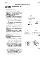
Each wire is identified by a four digit numerical
coding printed on the whole lenght every 20 to 30
mm (A).
This coding is also shown on the wiring diagrams of
electrical system (B).
On the general electrical system diagram attached,
numbers and letters are shown before the four digit
coding.
Numbers mean the wire section shown in mm
2
.
The following letters indicate the wire colours;
where W stands for white, R for Red and Br for
Brown. See detail (C).
3. Precautions for connecting and disconnecting ter-
minal connectors.
1)
When disconnecting harnesses, grasp them
by their connectors. Do not pull on the wire
itself. Be sure to release the lock first before
attempting to separate connectors, if a lock is
provided. (Refer to “Instructions for Discon-
necting Connector” on page T5-6-3.)
2)
Water-resistant connectors keep water out so
that if water enters them, water will not easily
drain from them. When checking water-resi-
stant connectors, take extra care not to allow
water to enter the connectors. In case water
should enter the connectors, reconnect only
after the connectors are thoroughly dried.
3)
Before connecting terminal connectors, check
that no terminals are bent or coming off. In
addition, as most connectors are made of
brass, check that no terminals are rusting.
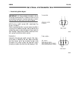
4)
When connecting terminal connectors pro-
vided with a lock, be sure to insert them to-
gether until the lock “clicks.”
Right
Wrong
Right
Rust
Wrong
(deformation)
Wrong
(Separation)
SM0651
SM0652
A
0511
0511
0511
20 ÷ 30 mm
B
0511
0511
C
2.5 R 0679
Содержание EX355 Tier2
Страница 22: ...T1 2 10 EX355 COMPONENT LAYOUT NOTES ...
Страница 37: ...T2 1 14 EX355 CONTROL SYSTEM NOTES ...
Страница 47: ...T2 2 10 EX355 HYDRAULIC SYSTEM NOTES ...
Страница 73: ...T2 3 26 EX355 ELECTRICAL SYSTEM NOTES ...
Страница 86: ...T3 1 12 EX355 PUMP DEVICE NOTES ...
Страница 94: ...T3 2 8 EX355 SWING DEVICE NOTES ...
Страница 113: ...EX355 T3 3 19 CONTROL VALVE Port b Check Valve 2 Port a Boom Cylinder Port c Check Valve 1 SM6068 ...
Страница 134: ...T3 4 10 EX355 PILOT VALVE NOTES ...
Страница 146: ...T3 5 12 EX355 TRAVEL DEVICE NOTES ...
Страница 156: ...T3 7 4 EX355 OTHER COMPONENTS Undercarriage NOTES ...
Страница 195: ...T4 2 6 EX355 STANDARD NOTES ...
Страница 199: ...T4 3 4 EX355 ENGINE TEST NOTES ...
Страница 215: ...T4 4 16 EX355 EXCAVATOR TEST NOTES ...
Страница 237: ...T4 5 22 EX355 COMPONENT TEST NOTES ...
Страница 265: ...T5 2 12 EX355 COMPONENT LAYOUT NOTES ...
Страница 325: ...T5 4 52 EX355 TROUBLESHOOTING B ...
Страница 372: ...EX355 T5 6 9 ELECTRICAL SYSTEM INSPECTION ...
Страница 380: ...EX355 T5 6 17 ELECTRICAL SYSTEM INSPECTION 5 Identify the relay on the terminal board 6 Replace the relay SM5622 ...
Страница 385: ...T5 6 22 EX355 ELECTRICAL SYSTEM INSPECTION NOTE ...
Страница 425: ...W1 1 4 EX355 PRECAUTIONS FOR DISASSEMBLY AND ASSEMBLY NOTES ...
Страница 450: ...W2 3 8 EX355 MAIN FRAME NOTES ...
Страница 454: ...W2 4 4 EX355 PUMP DEVICE SM5510 ...
Страница 456: ...W2 4 6 EX355 PUMP DEVICE SM5510 ...
Страница 458: ...W2 4 8 EX355 PUMP DEVICE ASSEMBLE PUMP DEVICE SM6205 SM6206 ...
Страница 460: ...W2 4 10 EX355 PUMP DEVICE SM6205 SM6206 ...
Страница 462: ...W2 4 12 EX355 PUMP DEVICE SM6205 SM6206 ...
Страница 464: ...W2 4 14 EX355 PUMP DEVICE SM6205 SM6206 ...
Страница 468: ...W2 4 18 EX355 PUMP DEVICE SM6210 ...
Страница 470: ...W2 4 20 EX355 PUMP DEVICE SM6210 ...
Страница 472: ...W2 4 22 EX355 PUMP DEVICE SM6210 ...
Страница 474: ...W2 4 24 EX355 PUMP DEVICE SM5511 SM6219 ASSEMBLE MAIN PUMP ...
Страница 476: ...W2 4 26 EX355 PUMP DEVICE SM5511 SM6219 ...
Страница 478: ...W2 4 28 EX355 PUMP DEVICE SM5511 SM6219 ...
Страница 480: ...W2 4 30 EX355 PUMP DEVICE SM5511 SM6219 ...
Страница 482: ...W2 4 32 EX355 PUMP DEVICE SM5511 SM6219 ...
Страница 484: ...W2 4 34 EX355 PUMP DEVICE SM5511 SM6219 ...
Страница 486: ...W2 4 36 EX355 PUMP DEVICE SM5511 SM6219 ...
Страница 498: ...W2 4 48 EX355 PUMP DEVICE NOTES ...
Страница 532: ...W2 5 34 EX355 CONTROL VALVE NOTES ...
Страница 540: ...W2 6 8 EX355 SWING DEVICE SM6277 31 18 17 20 19 21 3 24 27 25 26 10 ...
Страница 542: ...W2 6 10 EX355 SWING DEVICE SM6277 31 19 2 1 23 22 ...
Страница 566: ...W2 7 12 EX355 PILOT VALVE 11 19 17 18 1 2 3 8 13 14 16 15 SM1114 ...
Страница 572: ...W2 7 18 EX355 PILOT VALVE 8 6 7 1 3 4 5 9 21 2 SM1119 ...
Страница 586: ...W2 7 32 EX355 PILOT VALVE NOTES ...
Страница 592: ...W2 8 6 EX355 PILOT SHUT OFF VALVE NOTES ...
Страница 602: ...W2 10 6 EX355 SOLENOID VALVE UNIT NOTES ...
Страница 621: ...W3 2 10 EX355 TRAVEL DEVICE SM5108 44 8 13 12 1 45 46 28 27 25 26 24 36 38 30 31 32 ...
Страница 623: ...W3 2 12 EX355 TRAVEL DEVICE 29 SM5108 42 44 8 13 12 1 2 23 8 9 10 43 17 11 15 14 41 40 21 20 22 18 19 16 30 31 32 ...
Страница 627: ...W3 2 16 EX355 TRAVEL DEVICE SM5502 3 4 5 20 7 8 9 10 12 14 13 16 11 6 ...
Страница 633: ...W3 2 22 EX355 TRAVEL DEVICE SM5111 Cross Section A 36 38 40 24 23 34 35 28 37 39 22 21 19 30 29 31 33 ...
Страница 643: ...W3 2 32 EX355 TRAVEL DEVICE NOTES ...
Страница 651: ...W3 3 8 EX355 CENTER JOINT NOTES ...
Страница 655: ...W3 4 4 EX355 TRACK ADJUSTER 8 14 13 11 17 12 SM6284 ...
Страница 657: ...W3 4 6 EX355 TRACK ADJUSTER 3 4 8 10 16 15 14 SM6284 ...
Страница 659: ...W3 4 8 EX355 TRACK ADJUSTER 3 6 4 8 10 9 SM6284 18 ...
Страница 667: ...W3 4 16 EX355 TRACK ADJUSTER NOTES ...
Страница 671: ...W3 5 4 EX355 FRONT IDLER 1 SM6290 2 4 3 5 6 8 12 7 6 3 4 1 2 9 10 11 ...
Страница 682: ...EX355 W3 6 7 UPPER AND LOWER ROLLER DISASSEMBLE UPPER ROLLER NOTE Replace the upper roller as an assembly SM1241 ...
Страница 689: ...W3 6 14 EX355 UPPER AND LOWER ROLLER NOTES ...
Страница 708: ...W4 1 10 EX355 FRONT ATTACHMENT NOTES ...
Страница 716: ...W4 1 18 EX355 FRONT ATTACHMENT NOTES ...
Страница 744: ...W4 2 28 EX355 CYLINDERS NOTES ...
Страница 763: ...EX355 W5 1 17 GENERAL INFORMATION Oil Pan N m kgf m Ib ft SM7010 ...
Страница 765: ...EX355 W5 1 19 GENERAL INFORMATION Water Pump N m kgf m Ib ft SM7012 ...
Страница 815: ...EX355 W5 3 35 ENGINE OVERHAUL Disassembly SM7093 1 Camshaft gear 2 Knock pin 3 Camshaft ...
Страница 855: ...EX355 W5 3 75 ENGINE OVERHAUL OIL PAN Removal 1 Clip 4 Oil strainer 2 Oil pan 5 Gasket 3 Gasket SM7187 ...
Страница 861: ...EX355 W5 3 81 ENGINE OVERHAUL PISTON Removal 1 Bearing cap 3 Bearings 2 Bolt 4 Piston with connecting rod SM7199 ...
Страница 883: ...EX355 W5 3 103 ENGINE OVERHAUL Reassembly 1 Crankshaft 3 Crankshaft gear 2 Pin SM7239 ...
Страница 894: ...W5 3 114 EX355 ENGINE OVERHAUL NOTE ...
Страница 908: ...W5 5 2 EX355 ENGINE COOLING SM7287 THERMOSTAT Disassembly 1 Water outlet pipe 3 Gaskets 2 Thermostats ...
Страница 918: ...W5 6 4 EX355 ENGINE FUEL FUEL FILTER Disassembly 1 Fuel filter 3 Fuel filter body 2 Overflow valve SM7305 ...
Страница 938: ...W5 7 6 EX355 ENGINE INDUCTION NOTE ...
Страница 958: ...W5 8 20 EX355 STARTING AND CHARGING NOTE ...


