


Festo — VTSA-F-CB — 2021-06a
Modification
81
4.
1
2
2
3
4
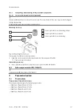
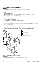
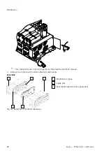
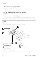
Fig. 44: Assembly of right end plate
1
Manifold sub-base
2
Guide pins
3
Seal (optionally with duct separation)
4
Right-hand end plate
1. Replace damaged seals.
2. Place the seal on the guide pins.
3. Screw in the screws of the components.
Tighten screws.
–
Tightening torque: 3.0 Nm ± 10%
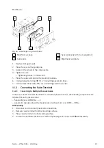
5. Place the valve terminal on the mounting surface.
6. Connect pneumatic lines
7.1.2 Connecting pneumatic lines.
7.2.1 Connecting electrical cables.
11.2
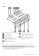
Converting the Valve Terminal
11.2.1
Converting to Multiple Pressure Zones
In order to convert the valve terminal to 2 and more pressure zones, the following components are
required for each pressure zone:
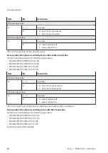
–
Separating seal VABD-S6-1-...-C
–
pneumatic supply plate with exhaust plate or exhaust air cover VABF-...-1P1A...
Disassembly
1. Disconnect electrical and pneumatic connections.
2. Remove valve terminal from the mounting surface.
3. Place valve terminal on a flat working surface.
4. Loosen the manifold sub-base to which a separating seal is to be fitted