


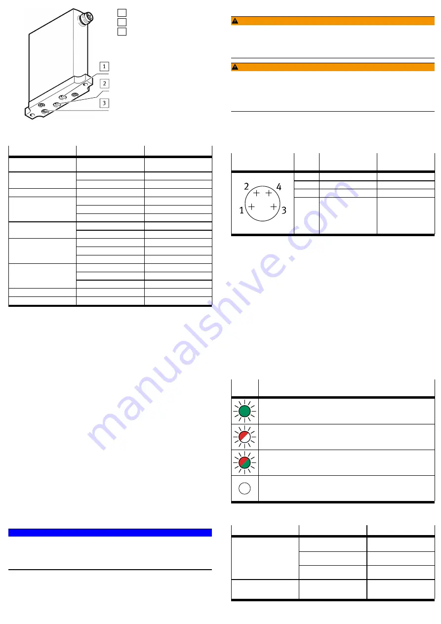
1 Working air port (2)
2 Exhaust air port (3)
3 Compressed air port (1)
Fig. 5 View from beneath
5.2.2
Product Variants
Characteristic
Type code
Description
Basic function
VEAA
Piezo proportional-pressure
regulator
L
In-line valve
Valve type
B
Sub-base valve
Valve function
3
3/3-way valve, normally closed
D2
0 … 2 bar
D9
0 … 6 bar
Pressure range
D11
0 … 10 bar
F
Flange/sub-base
Pneumatic connection
Q4
Push-in connector 4 mm
V1
Voltage variant 0 … 10 V
V2
Voltage variant 0 … 5 V
Setpoint value input
A4
Current variant 4 … 20 mA
V1
Voltage variant 0 … 10 V
V2
Voltage variant 1 … 5 V
Actual value output
A4
Current variant 4 … 20 mA
Nominal operating voltage
1
24 V DC
Electrical connection
R1
M8 plug, 4-pin
Tab. 3 Product Variants
6
Transport and storage
–
Store the product in a dry, UV- and corrosion-protected environment.
–
Ensure short storage times.
7
Mechanical installation
1. Make sure there is sufficient space for the connecting cable and tubing con-
nections.
Ä
This will prevent kinks from forming in the connecting cables and the
tubing.
2. Place the valve as close to the consumer as possible.
Ä
This leads to improved control precision and shorter response times.
Options for mounting the valve:
–
Mounting the in-line valve via 3 lateral through-holes
–
Mounting the in-line valve to H-rails using H-rail mounting VAME-P7-T
è
1.1 Further applicable documents
–
Mounting the in-line valve to the mounting plate VAME-P6-Y
è
1.1 Further applicable documents
–
Mounting the sub-base valve via 2 through-holes using the sub-base
VABM-...
è
1.1 Further applicable documents
8
Installation
8.1
Pneumatic Installation (In-line Valve)
1. Attach the tubing to the following connections:
–
Compressed air port (1)
è
–
Working air port (2)
è
2. Fit a silencer at the exhaust port (3) or provide for ducted exhaust air
è
–
Operating medium
NOTICE!
Pay attention to compressed air quality.
Damage to property or loss of function from lubricated compressed air.
•
Operate product only with unlubricated compressed air.
•
Observe the requirements for compressed air quality
è
Technical data.
8.2
Electrical Installation
WARNING!
Risk of injury due to electric shock.
•
For the electric power supply, use only PELV circuits that ensure a reliable
electric disconnection from the mains network.
•
Observe IEC 60204-1/EN 60204-1.
WARNING!
Risk of Injury due to Electric Shock.
If the housing is damaged (for example due to cracks), protection against danger-
ous voltage is no longer guaranteed.
•
Do not start the device.
•
Immediately shut down the device.
1. If a screened cable is used: earth the shield at the cable end farther away
from the valve.
2. Install electrical connecting cable without squeezing, kinking or stretching.
3. Screw electrical connecting cable onto the M8 plug connector. Tightening
torque: maximum 0.3 Nm
Connection
Pin
Allocation
Wire colour
1)
(NEBU-M8...)
1
+ 24 V DC
BN
2
Setpoint value (+)
WH
3
GND
BU
4
Actual value (+)
BK
1) in accordance with IEC 757
Tab. 4 Pin allocation for plug M8, 4-pin
9
Commissioning
1. Check the operating conditions and limit values
è
Technical data.
2. Switch on compressed air supply.
3. Check pneumatic connection points for tightness.
4. Connect valve to a setpoint signal.
5. Switch on operating voltage.
10
Cleaning
1. Switch off the following energy sources to clean the outside:
–
Compressed air
–
Operating voltage
2. Clean the outside of the product with a soft cloth. Do not use aggressive
cleaning agents.
11
Malfunctions
11.1
Diagnostics
LED
indicator
Status and meaning
LED lights up green:
–
The operating voltage is present and within the permissible range.
–
No error is present.
–
The setpoint signal is in the permissible range (0 … 10.8 V or 2.5 … 20.5 mA).
LED flashes red:
–
The operating voltage is above the permissible range (
>
29 V).
LED flashes alternately red and green:
–
The setpoint signal is above the permissible range (
>
10.8 V or
>
20.5 mA).
–
The setpoint signal is below the permissible range (
<
2.5 mA)
LED is off:
–
No operating voltage applied.
–
The operating voltage is below the permissible range (
<
19 V).
Tab. 5 LED
11.2
Fault clearance
Fault description
Cause
Remedy
Operating voltage not applied
Check the operating voltage
connection.
No setpoint voltage
Check the controller and con-
nection.
Valve does not respond.
No/insufficient compressed air
supply
Check compressed air supply.
Flow rate is too low.
Restriction of the flow cross
section due to connection tech-
nology (swivel fittings).
Use alternative connection
technology.


