


Sensor box
SRAP−M−CA1−...
Festo AG & Co. KG
Postfach
D−73726 Esslingen
++49/711/347−0
www.festo.com
(en) Operating instructions
745898
1006NH
Original: de
1
Operating elements and connections
1
2
3
4
5
6
8
9
aJ
aA
aB
aC
8
7
aD
4
a
2
a
1
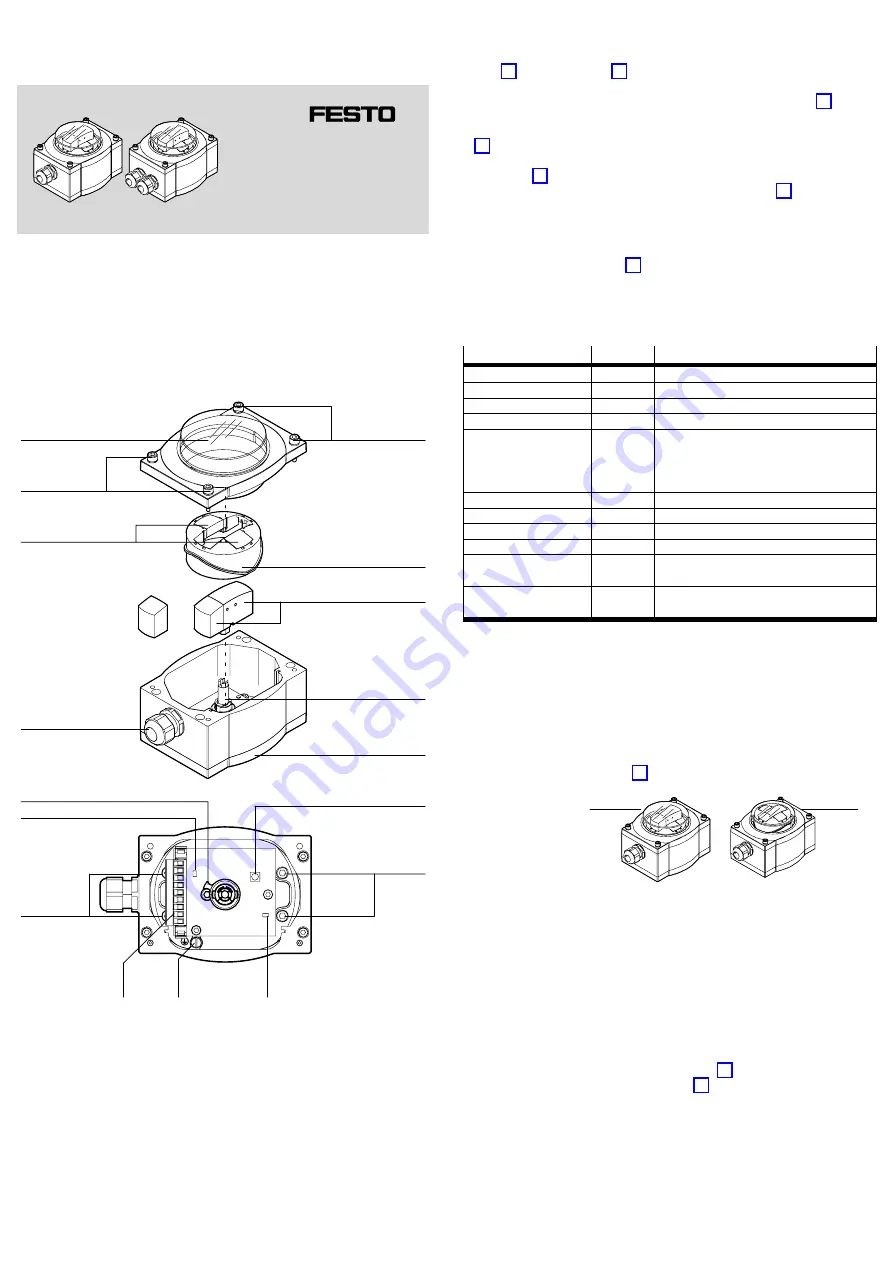
Cover with plastic cap
2
Socket head screws (M5)
3
Indicator ring of the position
indicator
4
Sections of the position indicator
5
Shaft
6
Baseplate
7
Teach button
8
Mounting screws
(captive)
9
LED (yellow) status display for
teach procedure
aJ
Earth terminal
aA
Terminal strip
aB
LED (green) power supply
indicator
aC
Magnet holder
aD
Cable connector (max. 2)
a = included separately
Fig.1: Design, operating elements and connections of the sensor box
2
Design
The sensor box SRAP is contained in a sturdy aluminium housing. A transparent
plastic cap in the cover allows the three−dimensional visual position indicator to be
seen (
1
). A shaft (
5
) leads outwards from the centre of the
baseplate, and is linked mechanically with the position indicator. On the sides, the
sensor box has up to two cable connectors, depending on the model (
aD
).
The visual position indicator is comprised of sections. The sections can be put
together so as to display the flow paths of single−way or multiple−way valves
(
3
and
4
).
The housing contains the device electronics and a 9−pin terminal strip for electrical
connection (
aA
). The device electronics include an analogue sensor which
picks up the movement of the shaft via a co−rotating magnet (
aC
) and
converts it into an analogue current signal.
The device electronics also include a microcontroller which conditions the sensor
signal so that the start and end point of the measuring range can be defined indi
vidually using a "teach" procedure.
Four captive mounting screws (
8
) in the baseplate of the sensor box are
for mounting it mechanically on quarter−turn actuators having a mechanical inter
face in accordance with VDI/VDE Guideline 3845 (hole pattern 30 x 80 [mm] ).
The sensor box SRAP is available in various designs. Position indicators can be
supplied in a range of colours and materials, and with a number of cable connector
options.
Features
Type code
Description
Sensor function
SRAP
Sensors for angular position, analogue, series P
Product design
M
Mainly metal
Design
C
Box module
Mechanical interface
A1
Direct mounting, hole pattern 30 x 80 mm
Type of display
Without display
yp
p y
BB
Blue/black
1)
GR
Green/red
1)
YB
Yellow/black
1)
Measuring range
270
Angle of rotation 0 ... 270°
Nominal operating voltage
1
24 V DC
Output signal
A
4 to 20 mA
Electrical connection
T
Terminal box (terminal strip)
Valve connection
No valve connection
2
With valve connection (two cable glands)
2)
Cable connection
M20
With cable gland M20, metal
P20
With cable gland M20, polymer
1)
Blue, green or yellow for valve open; black or red for valve closed
2)
To relay the control signal for a solenoid valve through the sensor box
Fig.2: Type code of the sensor box SRAP
3
Function
The rotation of the quarter−turn actuator and valve mounted under the sensor box
is transmitted to the shaft of the sensor box. The shaft transmits the rotation to
the visual position indicator.
The visual position indication shows whether the valve is open or closed. When the
valve is open, the indicator ring (
3
) is lowered and the sections indicate
the flow path. A raised indicator ring indicates that the valve is closed.
1
Indicator ring is
lowered (valve
open)
2
Indicator ring is
raised (valve
closed)
Fig.3: Example display for single−way v alves
1
2
The rotation of the shaft is evaluated with the aid of the co−rotating magnet by a
magnetically sensitive sensor element. The sensor signal is conditioned and output
as an analogue current signal. The sensor box SRAP returns an angle−proportional
output signal of 4 mA ... 20 mA within the taught measuring range.
If the end points of the defined measuring range are exceeded by up to 7.2° the
active output signal is kept constant (as a buffer to compensate for seal wear in
the process valve). If this range is exceeded (>7.2°), an output signal of 2 mA is
generated (out of range).
Two internal LEDs supply status information (visible during commissioning while
the housing cover is not in place). The green LED (
aB
) lights up when the
operating voltage is correct. The yellow LED (
9
) supplies status informa
tion about the teaching procedure. The teaching procedure allows the end points
of the measuring range to be set individually within the available turn angle
(0 ... 270°).


