7.2
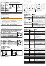
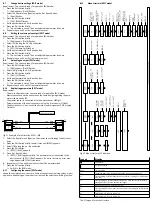
Inlet situation
The specified accuracies shown in the technical data of the sensor are achieved
when the conditions for the laminar flow inlet are observed on the sensor.
Measuring range
Min. internal
diameter of
laminar flow
inlet in mm
Design of
the laminar
flow inlet
-0.1
-0.5
-1
-5
-10
-50
-100
-200
2.9 (e.g. QS4)
Any
Permissible
1)
± 2%
2)
Not permissible
3)
4 (e.g. QS6)
Straight
4 (e.g. QS6)
Angle directly
on sensor
± 1%
2)
4 (e.g. QS6)
Angle at dis-
tance of
5 … 80 cm
Permissible
1)
± 10 %
2)
6 (e.g. QS8)
Any
Permissible
1)
1) Accuracy as specified in the technical data
2) Deviation from the specified accuracy.
3) Operation possible. But deviations of more than 20% must be expected.
Tab. 10 Effect of the inlet conditions and connection sizes on the specified accur-
acy
7.3
Electrical installation
WARNING!
Risk of injury due to electric shock.
•
For the electrical power supply, use only PELV circuits in accordance with IEC
60204-1/EN 60204-1 (Protective Extra-Low Voltage, PELV).
•
Observe the general requirements of IEC 60204-1/EN60204-1 for PELV cir-
cuits.
•
Only use voltage sources that ensure a reliable electric separation from the
mains network in accordance with IEC 60204-1/EN 60204-1.
Long signal lines reduce the immunity to interference.
•
Comply with the maximum permissible I/O signal line length of 30 m (in IO-
Link® operation: 20 m).
The binary outputs at pin 2 and pin 4 can be wired as PNP or NPN connections as
needed. Configure binary outputs according to your wiring in the [SPEC] menu
è
8.6 Configuring switching output (EDIT mode) and
è
Pin
Wire colour
1)
Allocation
Plug L1
1
Brown (BN)
Operating v24 V DC
2
Black (BK)
Switching output OutA, volume/load pulse
or IO-Link® (C/Q line)
3
White (WH)
Switching output OutB or analogue output
4
Blue (BU)
0 V
1) Colours apply for connecting cables NEBS-L1...
Tab. 11 Pin allocation of plug L1
Pin
Wire colour
1)
Allocation
Plug M8x1
1
Brown (BN)
Operating v24 V DC
2
White (WH)
Switching output OutB or analogue output
3
Blue (BU)
0 V
4
Black (BK)
Switching output OutA, volume/load pulse
or IO-Link® (C/Q line)
1) Colours apply for connecting cables NEBU-M8...
Tab. 12 Pin allocation of plug M8x1
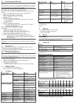
Circuit diagrams
SFAH…L1
SFAH…M8
Tab. 13 Circuit diagrams SFAH
8
Commissioning
8.1
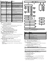
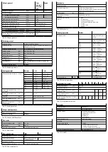
LCD display
1 Main display (e.g. measurement
value)
2 Status information
3 Lower display (e.g. unit)
4 Output display
Fig. 9 LCD display
Example for LCD display
Meaning
Output display
[OutA]
Switching output OutA selected/activated (flashes with
active IO-Link®)
[OutA]
Switching output OutA set
[OutB]
Switching output OutB selected/activated
[OutB]
Switching output OutB set
[Puls]
Analogue output for volume/load pulse selected/activated
[Anlg]
Analogue output for flow rate selected/activated
Status information / signal indicator
[Lock]
Security code activated
[Spec]
Special menu selected
[Option]
Illuminates when parameters having a special influence on
the measured value indicator have been changed (com-
pared to the factory setting): reference condition (stand-
ard), gas
Tab. 14
Example for LCD display
Meaning
Main display
Lower display
Measured value indicator and unit in RUN mode
[–0.53]
[L.Min]
Measured value indicator (here: negative value)
and unit
Menu for the switching outputs (OutA and OutB)
[Edit]
[bin]
[OutA] / [OutB]: Edit menu for the switching out-
puts (binary)
_|¯
[Fctn]
Threshold value comparator
_|¯|_
[Fctn]
Window comparator
d_|¯|_
[Fctn]
Auto difference monitoring
[18.0]
[SP]
Switching point value
[1.80]
[SP.Lo]
Value of lower switching point
[6.45]
[SP.Hi]
Value of upper switching point
[0.50]
[HY]
Hysteresis value
[18]
[t.obS] / [MSEC]
Time interval for determination of the signal
change, which is used to establish the reference
value.
[0.25]
[d.SP]
Threshold value for determining the monitoring
area
[NO]
[LOGC]
Switching characteristics: [NO] = normally open
contact, [NC] = normally closed contact
[bLUE]
[COLR]
Display colour
Extreme values (only SHOW mode)
[1.64]
[MIN]
Minimum measured value since switch-on of the
supply voltage or the last reset
[8.50]
[MAX]
Maximum measured value since switch-on of the
supply voltage or the last reset
[20.8]
[AVER]
Average of the flow rate measurement, filter time
constants
Additional settings (pulse at the output)
[100]
[PULSE]
Duration of the volume or load pulse at the out-
put
Analogue output
[Edit]
[ANLG]
Edit menu for the analogue output
[0...10]
[Out] / [V]
Output function of the analogue output
[100]
[In.Hi] / [%]
Scaling of the analogue output to the end value
of the flow measuring range in percent of FS
[-100]
[In.Lo] / [%]
Scaling of the analogue output to the start value
of the flow measuring range in percent of FS
Menu for device settings (Spec)
[Edit]
[Menu]
[Spec]: Edit menu for additional settings

