Festo Pick&Place Station Скачать руководство пользователя страница 1

678864 de/en 
04/06 R2.2 


Station Pick&Place 
Handbuch


Pick&Place station 
Manual 


CD-ROM included


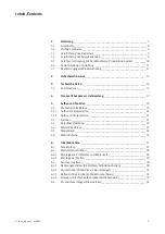
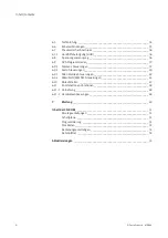
Содержание Pick&Place Station

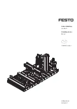
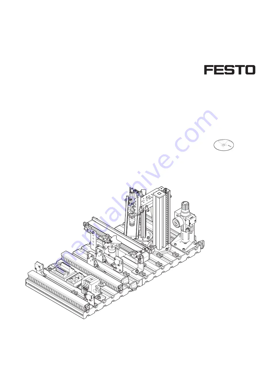
Страница 1: ...678864 de en 04 06 R2 2 Station Pick Place Handbuch Pick Place station Manual CD ROM included ...

Страница 2: ...or injury caused to trainees the training company and or any third party which may occur if the system is in use for purposes other than purely for training unless the said damage injury has been caused by Festo Didactic deliberately or through gross negligence Bestell Nr Order No Stand Status Autoren Authors Grafik Graphics Layout Layout 678864 04 2006 Frank Ebel Markus Pany Doris Schwarzenberger...

Страница 3: ...____________________ 21 5 1 2 Aufbau mit Folgestation ________________________________________ 21 5 2 Funktion _____________________________________________________ 22 5 3 Ablaufbeschreibung ___________________________________________ 22 5 4 Modul Pick Place _____________________________________________ 23 5 5 Modul Band __________________________________________________ 24 5 6 Modul Rutsche______...

Страница 4: ...________________________ 45 6 10 Ablauf starten ________________________________________________ 47 6 11 Kombination von Stationen______________________________________ 48 6 11 1 Vernetzung___________________________________________________ 48 6 11 2 Hardwareanpassungen _________________________________________ 48 7 Wartung _____________________________________________________ 49 Inhalt der CD ROM...

Страница 5: ...1 1 Set up as individual station _____________________________________ 71 5 1 2 Set up with downstream station__________________________________ 71 5 2 Function _____________________________________________________ 72 5 3 Sequence description __________________________________________ 72 5 4 Pick Place module ____________________________________________ 73 5 5 Conveyor belt module ________________...

Страница 6: ...__________________________ 95 6 10 Starting the sequence __________________________________________ 97 6 11 Combination of stations ________________________________________ 98 6 11 1 Networking___________________________________________________ 98 6 11 2 Hardware modifications ________________________________________ 98 7 Maintenance _________________________________________________ 99 Content of ...

Страница 7: ...dware setzt sich aus didaktisch aufbereiteten Industriekomponenten zusammen Die Station Pick Place liefert Ihnen ein geeignetes System mit dem Sie die Schlüsselqualifikationen Sozialkompetenz Fachkompetenz und Methodenkompetenz praxisorientiert vermitteln können Zusätzlich können Teamfähigkeit Kooperationsbereitschaft und Organisationsvermögen trainiert werden In Lernprojekten können die realen Pr...

Страница 8: ...rechtes Verwenden von optischen Reflex Lichttastern Fachgerechtes Verwenden von Endschaltern SPS Programmieren und Einsatz einer SPS Struktur eines SPS Programms Inbetriebnahme Inbetriebnahme einer Fertigungsanlage Fehlersuche Systematische Fehlersuche an einer Fertigungsanlage Themen für Projektarbeiten Auswahl pneumatischer Komponenten Linearantriebe Schwenkantriebe Vakuumgeneratoren Sicherheit ...

Страница 9: ...er verpflichtet sich nur Personen am MPS arbeiten zu lassen die mit den grundlegenden Vorschriften über Arbeitssicherheit und Unfallverhütung vertraut und in die Handhabung des MPS eingewiesen sind das Sicherheitskapitel und die Warnhinweise in diesem Handbuch gelesen und verstanden haben Das sicherheitsbewusste Arbeiten des Personals soll in regelmäßigen Abständen überprüft werden Alle Personen d...

Страница 10: ...n für Leib und Leben des Benutzers oder Dritter bzw Beeinträchtigungen an der Maschine oder an anderen Sachwerten entstehen Das MPS ist nur zu benutzen für die bestimmungsgemäße Verwendung und in sicherheitstechnisch einwandfreiem Zustand Störungen die die Sicherheit beeinträchtigen können sind umgehend zu beseitigen 1 5 Gefahren im Umgang mit dem Modularen Produktions System ...

Страница 11: ... von Anlagenteilen die einem Verschleiß unterliegen Unsachgemäß durchgeführte Reparaturen Katastrophenfälle durch Fremdkörpereinwirkung und höhere Gewalt Festo Didactic schließt hiermit jegliche Haftung für Schäden des Auszubildenden des Ausbildungsunternehmens und oder sonstiger Dritter aus die bei Gebrauch Einsatz der Anlage außerhalb einer reinen Ausbildungssituation auftreten es sei denn Festo...

Страница 12: ...1 Einleitung 12 Festo Didactic 678864 ...

Страница 13: ...pannungslosem Zustand Verwenden Sie nur Kleinspannungen maximal 24 V DC Pneumatik Überschreiten Sie nicht den zulässigen Druck von 800 kPa 8 bar Schalten Sie die Druckluft erst ein wenn Sie alle Schlauchverbindungen hergestellt und gesichert haben Entkuppeln Sie keine Schläuche unter Druck Seien Sie beim Einschalten der Druckluft besonders vorsichtig Zylinder können selbsttätig aus oder einfahren ...

Страница 14: ...2 Sicherheitshinweise 14 Festo Didactic 678864 ...

Страница 15: ...n Prüfen PR Be arbeiten BE Hand haben HA Puffern PU Pick Place PP Fluidic Muscle Presse FP Trennen TR Lagern LA Roboter R Montieren MO HS Sortieren SO Verteilen VE Prüfen PR Bearbeiten BE Handhaben HA Puffern PU Pick Place PP FluidicMuscle Presse FP Trennen TR Lagern LA Roboter R Montieren MO HS Montieren mit Stanzen Sortieren DP Verteilen AS Interface 3 Technische Daten 3 1 Kombinationen ...

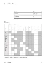
Страница 16: ...3 Technische Daten 16 Festo Didactic 678864 ...

Страница 17: ...actic zu melden Auspacken Beim Auspacken der Station das Füllmaterial der Transportbox vorsichtig entfernen Beim Auspacken der Station darauf achten dass keine Aufbauten der Station beschädigt werden Nach dem Auspacken die Station auf mögliche Beschädigungen überprüfen Beschädigungen sind unverzüglich dem Spediteur und Festo Didactic zu melden Lieferumfang Den Lieferumfang entsprechend dem Liefers...

Страница 18: ...4 Transport Auspacken Lieferumfang 18 Festo Didactic 678864 ...

Страница 19: ...lace wird das Einlegen eines Werkstückeinsatzes in ein Gehäuse realisiert Als Werkstückeinsätze stehen eine Uhr ein Thermometer und ein Hygrometer zur Verfügung Die Aufgabe der Station Pick Place ist es Werkstücke Gehäuse transportieren Werkstücke Gehäuse stoppen Werkstückeinsätze einlegen Komplette Werkstücke Gehäuse und Einsatz vereinzeln Hinweis Die Werkstückeinsätze Uhr Thermometer und Hygrome...

Страница 20: ...Funktion 20 Festo Didactic 678864 Der Aufbau der Station Pick Place besteht aus Modul Pick Place Modul Band Modul Rutsche Profilplatte Wagen Bedienpult SPS Board Station Pick Place mit Wagen Bedienpult und SPS Board ...

Страница 21: ...als Einzelstation Aufbau der Station Pick Place als Einzelstation bzw letzte Station einer Anlage Der Stopper am Ende des Bands ist montiert 5 1 2 Aufbau mit Folgestation Aufbau der Station Pick Place mit Folgestation Der Stopper am Ende des Bands ist demontiert ...

Страница 22: ... realisiert werden Aussortieren von Werkstücken Gehäuse oder Grundkörper auf die Rutsche Alternatives Zuführen von Werkstücken Gehäuse oder Grundkörper von der Rutsche Startvoraussetzung Kein Werkstück am Bandanfang Rutsche mit Werkstückeinsätzen gefüllt Ausgangsstellung Vereinzeler ausgefahren Bandmotor aus Mini Schlitten oben Mini Schlitten eingefahren Vakuum aus Ablauf 1 Wird das Werkstück erka...

Страница 23: ...ul ist aus präzisen Schlitteneinheiten aufgebaut Die Endlagen der Schlitten werden mit Näherungsschaltern erfasst Ein Faltenbalg Saugnapf erfasst die Werkstückeinsätze Direkt an den Faltenbalg Saugnapf ist ein Vakuumfilter montiert damit keine Schmutzpartikel in den Vakuumgenerator gelangen 5 4 Modul Pick Place ...

Страница 24: ...em Vereinzeler und am Bandende erfolgt durch optische Näherungsschalter mit Lichtleitern Der Antrieb des Gurtbandes erfolgt durch einen Gleichstrom Getriebemotor Durch einen angebauten Elektromagneten Drehmagnet mit Vereinzeler können die Werkstücke gestoppt und vereinzelt werden Die Endlagen werden mit induktiven Näherungsschaltern nachgewiesen 5 5 Modul Band ...

Страница 25: ...tic 678864 25 Das Modul Rutsche dient zum Transportieren oder Lagern der Werkstücke Durch die variable Einstellung von Neigung und Höhe ist dieses Modul universell einsetzbar 6 Werkstückeinsätze passen auf die Rutsche 5 6 Modul Rutsche ...

Страница 26: ...5 Aufbau und Funktion 26 Festo Didactic 678864 ...

Страница 27: ...lerweise auf eine Sichtprüfung auf einwandfreie Verschlauchung Verkabelung und das Anlegen der Betriebsspannung Alle Komponenten Verschlauchungen und Verkabelungen sind eindeutig gekennzeichnet so dass ein Wiederherstellen aller Verbindungen problemlos möglich ist Zur Inbetriebnahme der MPS Station benötigen Sie die montierte und justierte MPS Station ein Bedienpult ein SPS Board ein Netzgerät 24 ...

Страница 28: ...sto Didactic 678864 6 2 1 Montage von Profilplatte und Bedienpult 1 2 4x 4 4x 3 5 2x 6 1 Profilplatte 2 Hammermutter M6 32 4x 3 Wagen 4 Zylinderschraube M6x10 4x 5 Blechschraube 3 5x9 2x 6 Bedienpult 6 2 Mechanischer Aufbau ...

Страница 29: ... Didactic 678864 29 6 2 2 Montage der Station Hinweise zur Montage der Station entnehmen Sie bitte der Montageanleitung der Station Pick Place im Verzeichnis Deutsch 10_PickPlace Montageanleitungen der mitgelieferten CD ROM ...

Страница 30: ...der Handhilfsbetätigung des Magnetventils in die Endlage die abgefragt werden soll 3 Verschieben Sie den Näherungsschalter bis die Schaltzustandsanzeige LED einschaltet 4 Verschieben Sie den Näherungsschalter in die gleiche Richtung um einige Millimeter bis die Schaltzustandsanzeige wieder erlischt 5 Positionieren Sie den Näherungsschalter an der halben Strecke zwischen Einschalt und Ausschaltpunk...

Страница 31: ...Sie die Druckluftversorgung des Vakuumgenerators ein 2 Bringen Sie ein Werkstück so an den Vakuumsauger heran dass das Werkstück angesaugt wird 3 Drücken Sie den EDIT Knopf bis die LED am Druckschalter blinkt Beim Loslassen wird der aktuelle Druckwert als Schaltdruck gespeichert 4 Kontrollieren Sie ob das Werkstück sicher gehalten wird Lassen Sie hierzu die Schlitteneinheiten mehrmals von Endlage ...

Страница 32: ...andanfang bzw beim Vereinzeler 2 Montieren Sie die beiden Lichtleiter am Lichtleitergerät 3 Legen Sie ein schwarzes Werkstück an den Bandanfang 4 Drehen Sie evtl mit einem kleinen Schraubendreher an der Einstellschraube bis die Schaltzustandsanzeige LED einschaltet Hinweis Maximal 12 Umdrehungen der Einstellschraube sind zulässig 5 Kontrollieren Sie die Einstellung durch Einlegen schwarzer roter u...

Страница 33: ...chten Sie Sender und Empfänger Lichtleiter aus 3 Montieren Sie die Lichtleiter an den Lichtleitergeräten 4 Drehen Sie evtl mit einem kleinen Schraubendreher an der Einstellschraube bis die Schaltzustandsanzeige LED einschaltet Hinweis Maximal 12 Umdrehungen der Einstellschraube sind zulässig 5 Legen Sie ein Werkstück in den Erfassungsbereich der Lichtschranke Die Schaltzustandsanzeige erlischt Dok...

Страница 34: ...drehung auf 2 Starten Sie einen Probelauf 3 Drehen Sie die Drosselrückschlagventile langsam auf bis die gewünschte Schlittengeschwindigkeit erreicht ist Dokumente Datenblätter Drosselrückschlagventil 175056 im Verzeichnis Deutsch 10_PickPlace Datenblaetter der mitgelieferten CD ROM Bedienungsanleitungen Schlitteneinheiten 650901 im Verzeichnis Deutsch 10_PickPlace Bedienungsanleitungen der mitgeli...

Страница 35: ...A2 des SPS Boards in die Buchse XMA2 des E A Terminals der Station 5 SPS Board Bedienpult Stecken Sie den Stecker XMG1 des SPS Boards in die Buchse XMG1 des Bedienpults 6 SPS Board Netzgerät Stecken Sie die 4 mm Sicherheitsstecker in die Buchsen des Netzgerätes 7 PC SPS Verbinden Sie Ihren PC durch ein Programmierkabel mit der SPS 6 6 Kabelverbindungen ...

Страница 36: ...tift bzw einem Schraubendreher max Klingenbreite 2 5 mm hinein bis das Ventil schaltet 3 Stößel loslassen Feder stellt den Stößel der HHB in Ausgangsstellung zurück das Ventil kehrt in die Ruhestellung zurück nicht bei Impulsventilen 4 Bei rastender Verwendung der HHB Prüfen Sie nach dem Testen der Ventile ob alle Handhilfsbetätigungen wieder in Grundstellung stehen 5 Stellen Sie sicher das vor In...

Страница 37: ...d die CPU führt ein Urlöschen durch Jetzt können Sie den Betriebsartenschalter loslassen Wenn die STOP LED wieder in Dauerlicht übergeht hat die CPU das Urlöschen beendet Die Daten der MMC Micro Memory Card werden dabei nicht gelöscht Dies kann durch Verbindungsaufbau zur SPS im Menü Zielsystem Erreichbare Teilnehmer anzeigen und löschen aller Bausteine im Bausteinordner ausgelöst werden CPU31x Dr...

Страница 38: ...hivieren Archiv auswählen CD ROM Quellen SPS Programme Release C S7 MPS_C zip Öffnen Zielverzeichnis auswählen OK Dearchivieren Die dearchivierten Daten wurden im Projektverzeichnis abgelegt OK Dearchivieren Die folgenden Objekte wurden dearchiviert Sollen diese jetzt geöffnet werden Ja 9 Wählen Sie die entsprechende Hardwarekonfiguration und laden Sie diese in Ihre SPS SPS 313C SPS 313C 2DP SPS 3...

Страница 39: ...6 Inbetriebnahme Festo Didactic 678864 39 11 Laden Sie das Projekt in die Steuerung Zielsystem Laden Folgen Sie den Anweisungen auf dem Bildschirm 12 Betriebsartenschalter in Position RUN ...

Страница 40: ...rät einschalten 3 Druckluftversorgung einschalten 4 NOT AUS Taster entriegeln falls vorhanden 5 Warten Sie bis die SPS ihre Prüfroutinen beendet hat 6 Starten Sie die Programmiersoftware 7 Dearchivieren Sie die Datei 10PP_FEC zip im Verzeichnis Quellen SPS Programme Release C FEC der mitgelieferten CD ROM Projekt Dearchivieren Öffnen CD ROM Quellen SPS Programme Release C FEC 10PP_FEC zip Öffnen P...

Страница 41: ... Inbetriebnahme Festo Didactic 678864 41 8 Kompilieren Sie das Projekt Projekt Alles übersetzen 9 Laden Sie das Projekt in die Steuerung Online Projekt laden Folgen Sie den Anweisungen auf dem Bildschirm ...

Страница 42: ...ist eine zuvor erfolgte Konfiguration der erforderlichen Online Parameter Netzknoten Treiber mit RSLINXLite RSLogix 500 Um Konflikte mit der seriellen Schnittstelle zu vermeiden beenden Sie nach Gebrauch von RSLogix 500 auch RSLINXLite CPU ML 1500 Konfiguration Onlineparameter Warten Sie bis die SPS ihre Prüfroutinen beendet hat Starten Sie RSLINXLite Communications Configure Drivers in der Liste ...

Страница 43: ...alter auf REM bzw PROG Starten Sie die Programmiersoftware Wählen Sie im Menü Comms System Comms Steuerung markieren und Online klicken Nach erfolgtem Verbindungsaufbau wählen Sie nun im Menü Comms Clear Processor Memory und bestätigen Sie mit OK Wenn die COMM 0 LED erlischt ist der Speicher der SPS gelöscht und zum Laden der Programme bereit Öffnen Sie die Projektdatei 10_PP_K im Verzeichnis Quel...

Страница 44: ...me Release C ML 1500 10_PP_K Öffnen 7 Laden Sie das Projekt in die Steuerung Comms System Comms Steuerung auswählen auf Download klicken Bestätigen Sie die nachfolgenden Meldungen Revision note sure to proceed with Download want to go online mit Ja bzw OK 8 Betriebsartenschalter in Position REM bzw RUN ...

Страница 45: ...inen beendet hat CPU FX1N Stellen Sie den Betriebsartenschalter in Position STOP Starten Sie die Programmiersoftware Wählen Sie im Menü Online PLC Clear All und bestätigen Sie mit JA Der Speicher der SPS ist gelöscht und zum Laden der Programme bereit 6 Dearchivieren Sie die Projektdatei 10_PP_AS pcd im Verzeichnis Quellen SPS Programme Release C FX1N der mitgelieferten CD ROM Extras Project Resto...

Страница 46: ...e 46 Festo Didactic 678864 Project Rebuild all 8 Laden Sie das Projekt in die Steuerung Project Transfer Download to PLC nachfolgende Meldungen Transfer to PLC mit OK bestätigen 9 Betriebsartenschalter in Position RUN ...

Страница 47: ...es Tasters durchgeführt 5 Legen Sie ein Werkstück Gehäuse am Bandanfang auf 6 Starten Sie den Ablauf der Station Pick Place Der Start wird mit dem leuchtenden START Taster angefordert und nach dem Betätigen des Tasters durchgeführt Hinweise Der Ablauf kann durch Drücken des NOT AUS Tasters oder durch Drücken des STOP Tasters jederzeit unterbrochen werden Mit dem Schlüsselschalter AUTO MAN können S...

Страница 48: ... signalisiert die Station der Vorgängerstation ob sie zur Aufnahme eines Werkstückes bereit ist oder ob sie belegt ist Die Sensoren zur Verkettung mehrerer Stationen müssen sich gegenüberstehen und fluchten Die verketteten Stationen müssen über die Verbindungselemente mit Hammerkopfschrauben sicher miteinander verbunden sein Hinweis Bei der Station Verteilen ist nur der StationLink Empfänger monti...

Страница 49: ...bständen sollten die Linsen der optischen Sensoren der Faseroptiken sowie Reflektoren die aktive Fläche des Näherungsschalters die gesamte Station mit einem weichen fuselfreien Tuch oder Pinsel gereinigt werden Es dürfen keine aggressiven oder scheuernde Reinigungsmittel verwendet werden 7 Wartung ...

Страница 50: ...7 Wartung 50 Festo Didactic 678864 ...

Страница 51: ...lieferten CD ROM 665871 im Verzeichnis Deutsch 10_PickPlace gespeichert Station Pick Place Station Pick Place elektrisch Station Pick Place elektropneumatisch GRAFCET Station Pick Place E A Belegung Station Pick Place Inhalt der CD ROM Montageanleitungen Schaltpläne Programmierung Stücklisten ...

Страница 52: ... Terminal 034 035 Einschaltventil mit Filterregelventil 152 894 Getriebemotor Band 374 134 Kunststoffschlauch PUN 4x0 75 159 662 Kunststoffschlauch PUN 6x1 159 664 Lichtleiter Einweg 165 360 Lichtleiter Reflex Lichttaster 165 358 Lichtleitergerät 165 327 Lichtschranke Empfänger 165 323 Lichtschranke Sender 165 353 Minischlitten SLT 6 170 553 Minischlitten SLT 10 197 894 Näherungsschalter SME 10F 5...

Страница 53: ...to Didactic 678864 53 Aktuelle Informationen und Ergänzungen zur Technischen Dokumentation der MPS Stationen finden Sie im Internet unter der Adresse http www festo didactic de Services MPS Aktualisierungen ...

Страница 54: ...Aktualisierungen 54 Festo Didactic 678864 ...

Страница 55: ..._______________________ 71 5 1 2 Set up with downstream station__________________________________ 71 5 2 Function _____________________________________________________ 72 5 3 Sequence description __________________________________________ 72 5 4 Pick Place module ____________________________________________ 73 5 5 Conveyor belt module __________________________________________ 74 5 6 Slide module ...

Страница 56: ..._______________________ 95 6 10 Starting the sequence __________________________________________ 97 6 11 Combination of stations ________________________________________ 98 6 11 1 Networking___________________________________________________ 98 6 11 2 Hardware modifications ________________________________________ 98 7 Maintenance _________________________________________________ 99 Content of the...

Страница 57: ... didactically suitable industrial components The Pick Place station provides you with an appropriate system for practice orientated tuition of the following key qualifications Social competence Technical competence and Methodological competence Moreover training can be provided to instil team spirit willingness to cooperate and organisational skills Actual project phases can be taught by means of ...

Страница 58: ...or Correct use of diffuse sensors and light barriers Correct use of limit switches PLC Programming and use of a PLC Structure of a PLC program Commissioning Commissioning of a production system Fault finding Systematic fault finding on a production system Topics for project work Selecting pneumatic components Linear drives Rotary drives Vacuum generators Safety during pneumatic power failure Vacuu...

Страница 59: ...ndertakes to ensure that the MPS is used only by persons who are familiar with the basic regulations regarding operational safety and accident prevention and who have received instructions in the handling of the MPS have read and understood the chapter on safety and the cautionary notes in this manual Safety conscious working of the persons should be regularly vetted Prior to commencing work all p...

Страница 60: ... the system there is nevertheless a risk of physical or fatal injury to the user or third parties or of damage being caused to the machinery or other material assets The MPS is to be used only for its intended purpose and in an absolutely safe conditions Faults impairing safety must be rectified immediately 1 5 Risks involved in dealing with the Modular Production System ...

Страница 61: ...difications on the MPS Inadequate monitoring of components subject to wear Incorrectly carried out repairs Catastrophies as a result of foreign bodies and vis major Festo Didactic herewith rules out any liability for damage or injury to trainees the training company and or other third parties which may occur during the use operation of the system other than purely in a training situation unless su...

Страница 62: ...1 Introduction 62 Festo Didactic 678864 ...

Страница 63: ...ed Use only low voltages of up to 24 V DC Pneumatics Do not exceed the permissible pressure of 8 bar 800 kPa Do not switch on compressed until you have established and secured all tubing connections Do not disconnect air lines under pressure Particular care is to be taken when switching on the compressed air Cylinders may advance or retract as soon as the compressed air is switched on Mechanics Se...

Страница 64: ...2 Notes on safety 64 Festo Didactic 678864 ...

Страница 65: ...n Testing PR Proces sing BE Hand ling HA Buffer PU Pick Place PP Fluidic Muscle Press FP Separat ing TR Storing LA Robot R Assembly MO HS Sorting SO Distributing VE Testing PR Processing BE Handling HA Buffer PU Pick Place PP FluidicMuscle Press FP Separating TR Storing LA Robot R Assembly MO HS Assembly with Punching Sorting DP Distributing AS Interface 3 Technical data 3 1 Combinations ...

Страница 66: ...3 Technical data 66 Festo Didactic 678864 ...

Страница 67: ...port Unpacking Carefully remove the padding material in the container box when unpacking the station When unpacking the station make sure that none of the station assemblies have been damaged Check the station for any possible damaged once unpacked The carrier and Festo Didactic are to be notified immediately of any damage Scope of delivery Check the scope of delivery against the delivery note and...

Страница 68: ...4 Transport Unpacking Scope of delivery 68 Festo Didactic 678864 ...

Страница 69: ...mponent The Pick Place station inserts a workpiece insert into a workpiece housing The following workpiece inserts are available a clock a thermometer and a hygrometer The function of the Pick Place station is to transport workpieces housings to stop workpieces housings to insert workpiece inserts to separate out complete workpieces housing and insert Note The workpiece inserts Clock Thermometer a...

Страница 70: ...to Didactic 678864 The Pick Place station consists of the following Pick Place module Conveyor belt module Slide module Profile plate Trolley Control console PLC board Pick Place station with trolley control console and PLC board ...

Страница 71: ...et up of the Pick Place station as individual station or last station of a system A stopper is fitted at the end of the conveyor belt 5 1 2 Set up with downstream station Set up of the Pick Place station with a downstream station The stopper at the end of the conveyor belt is removed ...

Страница 72: ...on Segregation of workpieces housings or bodies onto the slide Alternative feed of workpieces housings or bodies from the slide Start prerequisites No workpieces at the start of the conveyor belt Slide filled with workpiece inserts Initial position Separator extended Belt drive switched off Mini slide up Mini slide retracted Vacuum off Sequence 1 The conveyor belt motor switches on if a workpiece ...

Страница 73: ...module is based on precise slide units End positions of the slides are sensed electrically via proximity sensors A bellows suction cup picks up the workpiece inserts Directly to the bellows suction cup a vacuum filter is mounted to prevent dirt particles to reach the vacuum generator 5 4 Pick Place module ...

Страница 74: ...r to the separator and at the end of the conveyor belt are detected by means of optical sensors with fibre optic cables The conveyor belt is driven by a DC gear motor Outgoing workpieces can be stopped or separated out by means of a solenoid actuated separator End position sensing of the separator is effected by means of inductive sensors 5 5 Conveyor belt module ...

Страница 75: ... 678864 75 The Slide module is used to transport or store the workpieces This module can be applied universally thanks to its variably adjustable inclination and height 6 workpiece inserts can be accommodated on the slide 5 6 Slide module ...

Страница 76: ...5 Design and function 76 Festo Didactic 678864 ...

Страница 77: ...ed to a visual check to ensure correct tubing connections wiring and supply of operating voltage All components tubing and wiring is clearly marked so that all connections can be easily re established The following is required to commission the MPS station The assembled and adjusted MPS station A control console A PLC board A power supply unit 24 V DC 4 5 A A compressed air supply of 6 bar 600 kPa...

Страница 78: ...o Didactic 678864 6 2 1 Assembling profile plate and control console 1 2 4x 4 4x 3 5 2x 6 1 Profile plate 2 T head nut M6 x 32 4x 3 Trolley 4 Socket head screw M6x10 4x 5 Screw 3 5x9 2x 6 Control console 6 2 Mechanical set up ...

Страница 79: ...ic 678864 79 6 2 2 Assembling the station Instructions on assembling the station please find in the assembly instructions of the Pick Place station in the directory English 10_PickPlace Assembly instructions on the CD ROM supplied ...

Страница 80: ...ich you wish to interrogate 2 Shift the sensor until it switches switching status display LED is on 3 Shift the sensor a few millimetres further in the same direction until it switches back LED is off 4 Place the switch half the way between the switch on and the switch off position 5 Tighten the clamping screw of the sensor with a hexagon screwdriver A F 1 3 6 Start a test run to check if the sens...

Страница 81: ...compressed air supply for the vacuum generator 2 Move a workpiece close to the vacuum suction cup until it is picked up 3 Push the EDIT button until the LED of the pressure switch is flashing Release the button The actual pressure value is stored as switching pressure 4 Start a test run to check if the workpiece is picked up securely Move the mini slides from end position to end position The workp...

Страница 82: ...start of the conveyor belt 2 Connect the fibre optic cables to the fibre optic device 3 Place a black workpiece at the start of the conveyor belt 4 Adjust the potentiometer of the fibre optic device by means of a screwdriver until the switching status display changes to on Note Maximal 12 revolutions of the adjusting screw are permissible 5 Place workpieces at the start of the conveyor belt Note A...

Страница 83: ...mitter and receiver fibre optic cables 3 Connect the fibre optic cables to the fibre optic device 4 Adjust the potentiometer of the fibre optic device by means of a screwdriver until the switching status display changes to on Note Maximal 12 revolutions of the adjusting screw are permissible 5 Place workpieces in the sensing range of the light barrier The switching status display changes to off Do...

Страница 84: ...st run 3 Slowly open the one way flow control valves until the desired speed is reached Documents Data sheets One way flow control valve 175056 in the directory English 10_Pick Place Data sheets on the CD ROM supplied Operating instructions Pneumatic cylinders 391172 in the directory English 10_Pick Place Operating instructions on the CD ROM supplied A visual check must be carried out before each ...

Страница 85: ... board into the XMA2 socket of the I O terminal of the station 2 PLC board control console Plug the XMG1 plug of the PLC board into the XMG1 socket of the control console 3 PLC board power supply unit Plug the 4 mm safety plugs into the sockets of the power supply unit 4 PC PLC Connect your PC to the PLC by means of a programming cable 6 6 Cable connections ...

Страница 86: ...h of blade 2 5mm 3 Release the stem the spring resets the stem of the manual override back to the starting position the valve moves back to the starting position not with double solenoid valves 4 For locking manual override usage Controll all manual overrides for being in starting position after testing the valves 5 Before commissioning the station make sure that all valves of the valve terminal a...

Страница 87: ... STOP LED starts to flash rapidly and the CPU carries out a memory reset You can let go of the mode selector When the STOP LED comes on permanently again the CPU has completed the memory reset The data on the MMC Micro Memory Card are not deleted This can be done by switching to the connected PLC via menu PLC Display Accessible Nodes and deleting all blocks in the block folder CPU31x Turn the mode...

Страница 88: ...an archive CD ROM Sources PLC Programs Release C S7 MPS_C zip Open Select destination directory OK Retrieving The retrieved data were stored in the project directory OK Retrieve The following objects were retrieved Do you want to open these now Yes 9 Select the hardware configuration and download it to the controller PLC 313C PLC 313C 2DP PLC 314 PLC 315 2DP 10 Select the project 10PP_AS or 10PP_K...

Страница 89: ...6 Commissioning Festo Didactic 678864 89 11 Download the project to the controller PLC Download Follow the instructions on the screen 12 Turn the mode selector switch of the CPU to RUN position ...

Страница 90: ...h on power supply unit 3 Switch on the compressed air supply 4 Release the EMERGENCY STOP pushbutton if available 5 Wait until the PLC has carried out its test routines 6 Start the PLC programming software 7 Restore the file 10PP_FEC zip from the directory Sources PLC Programs Release C FEC of the CD ROM supplied Project Restore Open CD ROM Sources PLC Programs Release C FEC 10PP_FEC zip Open Rest...

Страница 91: ...6 Commissioning Festo Didactic 678864 91 8 Compile the project Project Build Project 9 Download the project to the controller Online Download Project Follow the instructions on the screen ...

Страница 92: ...e following operating steps is to configurate the necessary online parameter nodes devices with RSLINXLite RSLogix 500 After using shutdown and exit RSLogix 500 and RSLINXLite to avoid conflicts with the serial interface CPU ML 1500 Onlineparameter configuration Wait until the PLC has carried out its test routines Start the RSLINXLite software Communications Configure Drivers select the setting RS...

Страница 93: ...he mode selector switch to REM or PROG Start the PLC programming software Select Comms System Comms select the required controller and click Online After connection the PLC and the PC select Comms Clear Processor Memory and confirm with OK When the COMM 0 LED stops blinking the memory reset is completed The PLC is ready for program download Open the file 10_PP_K from the directory Sources PLC Prog...

Страница 94: ...rograms Release C ML 1500 10PP_K Open 7 Download the project to the controller Comms System Comms select controller click Download Confirm the following notes Revision note sure to proceed with Download want to go online with Yes or OK 8 Turn the mode selector switch of the CPU to RUN position ...

Страница 95: ...memory 6 Wait until the PLC has carried out its test routines CPU FX1N Turn the mode selector switch to STOP Start the PLC programming software Select Online PLC Clear All and confirm with Yes The memory reset is completed The PLC is ready for program download Restore the file 10_PP_AS pcd from the directory Sources PLC Programs Release C FX1N of the CD ROM supplied Extras Project Restore select a...

Страница 96: ...to Didactic 678864 Project Rebuild all 8 Download the project to the controller Project Transfer Download to PLC Confirm the following notes Transfer to PLC with OK 9 Turn the mode selector switch of the CPU to RUN position ...

Страница 97: ...been pressed 5 Put a workpiece housing at the start of the conveyor belt 6 Start the sequence of the Pick Place station The start is prompted by the illuminated START button and carried out when the pushbutton has been actuated Notes The sequence can be interrupted at any time by pressing the EMERGENCY STOP pushbutton or by pressing the STOP pushbutton With the key operated switch AUTO MAN you can...

Страница 98: ...tation signals the upstream station whether it is ready to receive a workpiece or busy The sensors for linking several stations must be arranged face to face in alignment The linked stations must be securely interconnected by means of hammer head screws Note In the case of the Distributing station only the StationLink receiver is mounted and on the Sorting station only the StationLink transmitter ...

Страница 99: ...e following should be cleaned at regular intervals using a soft fluff free cloth or brush The lenses of the optical sensors the fibre optics and reflectors The active surface of the proximity sensor The entire station Do not use aggressive or abrasive cleaning agents 7 Maintenance ...

Страница 100: ...7 Maintenance 100 Festo Didactic 678864 ...

Страница 101: ...ctory English 10_Pick Place on the CD ROM 665871 supplied Pick Place station Pick Place station electrical Pick Place station electropneumatic GRAFCET Pick Place station I O allocation list Pick Place station Content of the CD ROM Assembly instructions Circuit diagrams Programming Parts lists ...

Страница 102: ...ibre optic device 165 327 Filter ESF 191 203 Fitting 186 117 Gear motor conveyor belt 374 134 I O terminal 034 035 Mini slides SLT 6 170 553 Mini slides SLT 10 197 894 One way flow control valve type C 175 056 Plastic tubing PUN 4x0 75 159 662 Plastic tubing PUN 6x1 159 664 Pressure switch SDE5 V1 527 458 Proximity sensor SME 10 525 914 Silencer U M5 004 645 Socket connector cable SIM M8 4GD 158 9...

Страница 103: ... Festo Didactic 678864 103 Up to date information and additional documents for the Technical documentation of the MPS stations please find at the address http www festo didactic de Services MPS Updates ...

Страница 104: ...Updates 104 Festo Didactic 678864 ...

Отзывы: