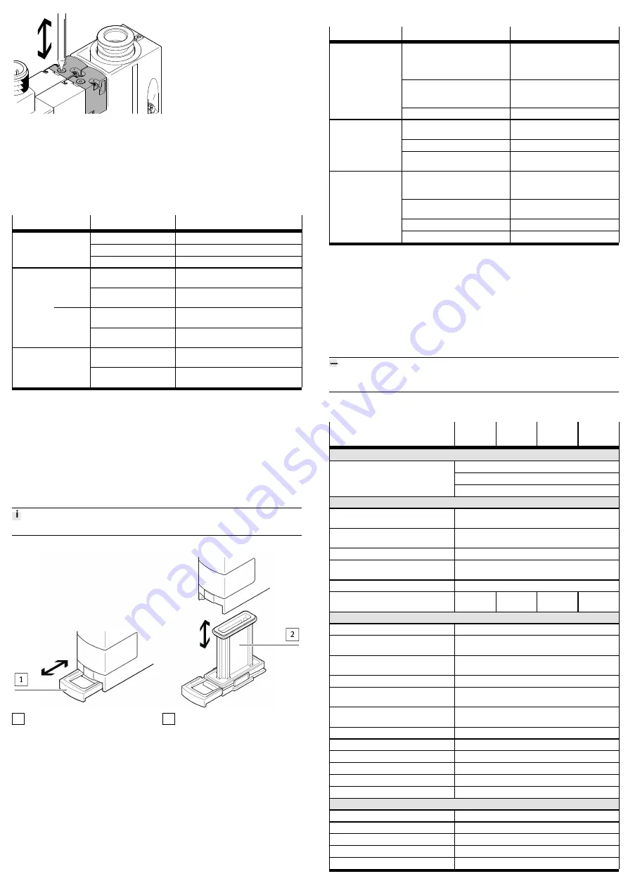
Fig. 7
1. Press in the plunger of the manual override with a blunt pin.
Ä
The solenoid valve switches.
2. Remove pin.
Ä
The plunger of the manual override is automatically reset. The solenoid
valve returns to the initial position.
9.3
Electrical manual override
9.4
Vacuum generator status indicator
LED
Status
Meaning
off
Switching point not reached
lights
Switching point is reached
Out
flashes
Teach procedure is started
off
Solenoid valve for vacuum is not switched,
vacuum is not generated
CE/CN/C-
PE
light on
Solenoid valve for vacuum is switched,
vacuum is generated
off
Solenoid valve for vacuum is not switched,
vacuum is generated
Vacuum
ON/OFF
OE/ON/O-
PE
lights
Solenoid valve for vacuum is switched,
vacuum is not generated
off
Solenoid valve for ejector pulse is not
switched, ejector pulse is not generated
Eject
lights
Solenoid valve for ejector pulse is
switched, an ejector pulse is generated
Tab. 14 Vacuum generator status indicator
10
Maintenance and care
Clean device
1. Switch off energy sources:
–
Operating voltage
–
Compressed air
2. Clean device with non-abrasive cleaning agents.
3. Check air filter through the display window for dirt.
Replace air filter
The air filter cannot be replaced in the vacuum generator OVEM-...-20/-30-C
1 Gate valve
2 Filter
Fig. 8 Remove/install air filter
1. Exhaust the vacuum generator.
2. Carefully pull gate valve
1
out to the first detent. The gate valve must stay in
this position on the filter.
3. Pull filter
2
out. Clean with white spirit.
4. Push filter into the housing.
5. Push in gate valve.
Ä
The gate valve pushes the filter into the vacuum generator.
11
Fault clearance
11.1
Malfunctions
Malfunction
Possible cause
Remedy
device-independent vacuum
between workpiece and suction
gripper, ejector pulse not activated
or sufficiently dimensioned
–
Activate ejector pulse when
lifting the suction gripper.
–
Increase duration and intensity
of ejector pulse.
Tubing dimensioned incorrectly
–
Replace tubing (tubing dimen-
sions
è
Workpiece is not
released by the suction
gripper
Flow control screw closed
–
Open flow control screw.
Short circuit or overload at the out-
put
–
Eliminate short circuit/over-
load.
Device faulty
–
Replace device.
Switching output does
not react in accordance
with the settings
Incorrect switching point taught
(e.g. at 0 bar)
Repeat teach procedure
Operating voltage faulty
–
Apply permissible operating
voltage
è
Electrical connections swapped
–
Connect device correctly
è
No control signal
Check controller
No LED display for
switching inputs
Device faulty
–
Replace device.
Tab. 15 Malfunctions
12
Disassembly
1. Switch off energy sources:
–
Operating voltage
–
Compressed air
2. Disconnect pneumatic and electrical connections from the device.
3. Loosen mountings and remove device.
13
Disposal
ENVIRONMENT!
Send the packaging and product for environmentally sound recycling in accord-
ance with the current regulations
è
14
Technical data
OVEM-...
-05
-07/-10
-14/-20--
B/-BN
-20/-30--
C
General
c UL us - listed (OL)
RCM compliance mark
Approvals
KC mark
Characteristic values
Operating pressure OVEM-...-
QS/-GN/-PL
[bar]
2 … 6
Operating pressure OVEM-...-
QO/-GO/-PO
[bar]
2 … 8
Pressure measuring range
[bar]
–1 … 0
Overload pressure at vacuum
port
[bar]
£
5
Ready-state delay
[ms]
£
500
Dead time (evacuation and
ejection)
[ms]
£
12
£
22
£
35
£
60
Electronics
Nominal operating voltage
[V DC]
24 ± 15 %
Max. output current (per
switching output)
[mA]
100
Voltage drop (for all switch-
ing outputs)
[V]
£
1.5
No-load supply current
[mA]
<
70
Coil characteristics 24 V DC –
low current phase
[W]
0.3
Coil characteristics 24 V DC –
high current phase
[W]
2.55
Time until current reduction
[ms]
80
Capacitive load maximum DC
[mF]
£
100
Overload protection
Present
Inductive protective circuit
adapted to MZ, MY, ME coils
Insulation voltage
[V]
50
Surge resistance
[kV]
0.8
Max. current consumption
OVEM-...-1P/-1N
[mA]
180
without vacuum sensor
[mA]
30
Accuracy
[% FS]
± 0.5
Tolerance of fixed hysteresis
[% FS]
± 0.5
Short circuit current rating
Yes


