

1.
Applicable documents
All available documents on the product
www.festo.com/pk
Motor operating instructions
Shaft operating instructions
2.
Safety instructions and notes on mounting
Switch off power supply before mounting work.
Observe the safety information (
Applicable documents).
Clean shafts. The spring pins
3
/
4
only grip efficiently on dry and grease-
free drive shafts.
Each time after disconnecting or turning the motor, perform a homing
procedure.
Observe tightening torques. Unless otherwise specified, the tolerance is
±20 %.
3.
Intended use
Parallel kit EAMM-U-...-D...-...A/P/R-S1:
Connection of an axis to a motor in a parallel configuration that fulfils degree
of protection IP65 (
Section 14).
4.
Further information
Accessories
www.festo.com/catalogue
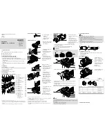
5.
Scope of delivery
5a.
Parallel kit EAMM-U-...-D...-...A/P/R-S1
15980d_1
1
Lower
part
2
Screw
3
Axis clamping sleeve
4
Motor
clamping
sleeve
5
Toothed
belt
6
Toothed
belt
pulley
7
Upper
part
8
Screw
9
Square
nut
1)
aJ
Screw
aB
Blanking plug
2)
aC
Adapter plate
3)
aD
Screw
3)
aE
O-ring
axis
4)
aF
Sealing ring for
aJ
aG
Motor seal
aH
Seal for
aC
5)
aI
Sealing ring for
2
bJ
Seal for
7
bB
Seal for
aC
3)
bC
O-ring motor
3)4)
(1x)
(4x)
(1x)
(1x)
(1x)
(2x)
(1x)
(7x)
(4x)
(4x)
(1x)
(1x)
(4x)
(1x)
(4x)
(1x)
(1x)
(4x)
(1x)
(1x)
(1x)
1)2)
1)
For EAMM-U-...-42A-S1, the mounting direction of the screws
2
differs. Attach the lower
part
1
to the motor by using the screws
2
and sealing rings
aI
. The square nuts
9
are not
required.
2)
For EAMM-U-110/-145, the blanking plug
aB
is included in the scope of delivery
5b.
Accessories (not included in delivery)
15346d_13
dA
Lubricating grease
LUB-KC1
(silicon-free)
dB
Clamping
element
6)
EADT-E-U1-110
(1x)
(1x)
6.
Mounting the lower part
1598
0d_2
0
Push the O-ring
aE
onto the
centring collar on the drive
cover of the axis.
1598
0d_2
Place sealing rings
aF
onto
the screws
aJ
.
Fasten the lower part
1
to
the axis by using the
screws
aJ
7)
.
1598
0d_3
0
With seal
aH
5)
:
Place the seal
aH
in the
recess of the lower part
1
.
Check: The notches (X) in the
seal
aH
are located over the
drill holes (Y).
1598
0d_3
6
With adapter plate
aC
3)
:
Place O-ring
bC
into the slot
of the adapter plate
aC
.
Fasten the adapter plate
aC
to the motor with the
screws
2
.
1598
0d_3
7
Position the seal
bB
on
the adapter plate
aC
.
Attach the motor to the
lower part
1
via the
adapter plate
aC
and the
seal
bB
by using the
screws
aD
.
Check: The motor can be
moved in the elongated holes.
1598
0d_2
7
Without adapter plate
aC
3)
:
Place the seal
aG
onto the
motor flange.
15980d_3
Place sealing rings
aI
onto
the screws
2
.
Attach the motor to the
lower part
1
by using the
screws
2
and square
nuts
9
1)
.
Check: The motor can be
moved in the elongated holes.
3)4)5)6)7)
3)
For EAMM-U-...-67A, the adapter plate
aC
, screws
aD
, seal
bB
and O-ring
bC
are included
in the scope of delivery.
4)
To distinguish between the O-rings
aE
and
bC
:
Section 13.
5)
The seal
aH
is included in the scope of delivery for motor interface 100A.
6)
For EAMM-U-110/-145, the clamping component
dB
is needed as a tool.
7)
If the tightening torques are exceeded, the cover screws of the axis will loosen during
disassembly.
7.
Mounting the toothed belt
15980d_4
Move the motor in the
direction of the axis as far as
its stop.
Grease the spring
pins
3
/
4
on the thread
and the outside of the cone
with lubricating grease
dA
.
Greased spring pins
3
/
4
can
be tightened evenly.
Screw the spring pins
3
/
4
into the threads of the toothed belt
pulleys
6
. Do not tighten.
Insert the toothed belt pulleys
6
into the toothed belt
5
.
Place the spring pins
3
/
4
onto the drive shafts.
Information
The position of the surface (A) depends on the size.
50/60
70/86
110/145
15346d_9
15980d_19
Position surfaces (A) approx. 1 mm above the reference surface (B).
Background: The tooth belt pulley
6
moves inwards when tightening.
15980d_5
Select the required tightening torque for the toothed belt pulleys
6
(
Section 10).
Tighten the toothed belt pulleys
6
. Apply counter pressure to the
spring pins
3
/
4
.
Check: The surfaces (A) of the toothed belt pulleys
6
are flush with the
reference surface (B) (tolerance: ± 0.5 mm).
15980d_8
Note
Comply with the tolerance.
If the toothed belt
5
or one of the toothed belt pulleys
6
is grinding against
the housing:
Unscrew the spring pin
3
/
4
slightly.
Readjust the toothed belt pulleys
6
.
8.
Tensioning the toothed belt
Note
A low toothed belt pretension is recommended.
Excessive toothed belt pretension can cause:
–
impermissible radial loads/breaking of the shafts
–
increased wear of the toothed belt
5
and the bearings of the axis and
motor.
Avoid excessive toothed belt pretension.
The toothed belt
5
is tensioned when the strands (C) run approximately
parallel.
Untensioned: y
,
x
Tensioned: y
L
1 … 1.05 x
15346d_22
8a.
For EAMM-U-50/-60/-70/-86
Move the motor by hand until the clamping force Fv is exerted on the
toothed belt
5
(
Table).
Tighten screws
2
.
8b.
For EAMM-U-110/-145
1534
6d_1
8
Place the clamping
element
dB
into the drill
hole (D) in the lower part
1
.
Tighten the clamping
element
dB
with a hex
wrench (
ß
8). Observe the
recommended torque
(
Table).
Tighten screws
2
.
1534
6d_1
7
Press the blanking plug
aB
into the drill hole (D).
EAMM-U- Recommended
torque
Clamping
force Fv
dB
[Nm]
5
[N]
15346d_24
15346d_25
15346d_23
50
−
−
−
15 … 35
60
−
−
−
40 … 70
70
−
−
−
60 … 110
86
−
−
−
70 … 130
110
0.2 … 0.6
0.4 … 0.8
0.6 … 1.0
120 … 300
145
1.0 … 1.5
1.5 … 2.0
2.0 … 2.5
200 … 450
Continuation on the reverse side!
Assembly instructions (Original instructions)
8064090
1704d
[8064092]
†‡
Parallel kit
EAMM-U-...-D...-...A/P/R-S1
Festo AG & Co. KG
Ruiter Straße 82
73734 Esslingen
Germany
+49 711 347-0
www.festo.com
aF
1
2
6
3
4
5
7
9
8
aB
aJ
aG
aH
aI
bJ
aE
dB
dA
1
aE
aJ
1
aF
aG
3
4
5
6
6
A
1
B
A
6
2
5
bC
bB
aC
aD
2
bA
1
aC
bB
aC
6
A
1
B
A
6
2
5
6
4
3
1
dB
D
2
C
C
1
aB
D
2
2
1
9
aI
1
aH
x
Y
aD
A
A
A


