6
1.1
XL-Wall
1.
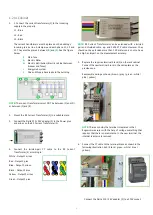
1. Connect the current transformers (1) to the incoming
supply in the property.
L1 - Blue
L2 - Red
L3 - Black
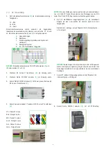
The current transformers must be placed on the building's
incoming service line. A clamp around each phase, L1, L2 and
L3. They must be placed between
(B)
and
(C)
. See the figure
below:
A.
Main fuse
B.
Electric Meter
C.
Electric distribution (Electric cabinet between
breaker and fuses)
D.
EnergyHub system
E.
One and three-phase loads in the building
NOTE!
The current transformers must NOT be between (C) and (D)
or between (C) and (E).
2.
Mount the RS Current Transformer (2) in a suitable place.
3.
Connect the Delta 230 / 24V adapter (3) to the Power plus
and minus on the RS Current Transformer (2).
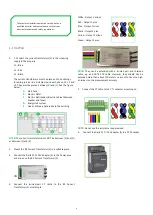
4.
Connect the twisted-pair CT cable to the RS Current
Transformer (2) according to:
White - Output 1 minus
Red - Output 1 plus
Blue - Output 2 minus
Black - Output 2 plus
Yellow - Output 3 minus
Green - Output 3 plus
NOTE!
They can be extended with a twisted pair and shielded
cable, e.g. and CAT6 STP cable. However, they should not be
extended more than about 100 meters so as not to have too high
an impact on the measurement accuracy.
5.
Connect the CT cable to the CT connector according to:
NOTE!
Do not use the resistance loop provided.
6.
Connect the Delta 230 / 24V adapter (3) to a 230V socket.
The electrical installation must be carried out by a
qualified installer and in accordance with current
electrical standards and safety regulations.
Содержание Rogowski 1200A
Страница 1: ...Installation manual Rogowski 600A 1200A 1800A Rev A01 ...
Страница 2: ......
Страница 10: ...Electricity Reinvented ...


