background image

B-LOC

®

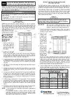
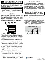
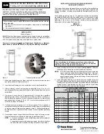
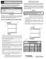
 Keyless Locking Devices provide a high 

capacity, zero-backlash shaft/hub or coupling 
connection by means of a mechanical interference 
fit. Referring to the series, please follow these 

Installation & Removal Instructions

 carefully 

to ensure proper performance of your B-LOC

®

 unit.

 ©2013 Fenner Drives   BLOCINST-003

For technical assistance, please 

call 1-717-665-2421 or email our 

Applications Engineering Group: 

[email protected].

B103

 ..................

2

B-PR-014

B106

 ..................

2

B-PR-014

B109

 ..................

3

B-PR-018

B112

 ..................

4

B-PR-012

B113

 ..................

5

B-PR-015

B115

 ..................

6

B-PR-013

B117

 ..................

7

B-PR-022

B400

 ..................

8

B-PR-016

B800

 ..................

9

B-PR-017

Shrink Discs

 ....

10

B-PR-020

Split 

Shrink Discs

 ....

11

B-PR-023

Half 

Shrink Discs

 ....

12

B-PR-024

SD40

 ................

13

B-PR-025

BCH

 ..................

14

B-PR-027

WK Rigid  

Couplings

 ........

15

B-PR-021

Installation & Removal Instructions  

for B-LOC

®

 Keyless Locking Devices

SEPT 

2013

US
www.fennerdrives.com

TEL: +1-800-243-3374

TEL: +1-717-665-2421

FAX: +1-717-665-2649

UK
www.fennerdrives.com

TEL:  +44 (0)870 757 7007

TEL:  +44 (0)1924 482 470

FAX:  +44 (0)1924 482 471

Содержание B-LOC B106

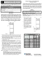
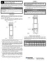
Страница 1: ...ons Engineering Group ae fennerdrives com B103 2 B PR 014 B106 2 B PR 014 B109 3 B PR 018 B112 4 B PR 012 B113 5 B PR 015 B115 6 B PR 013 B117 7 B PR 022 B400 8 B PR 016 B800 9 B PR 017 Shrink Discs 1...

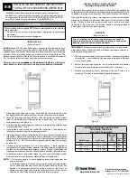
Страница 2: ...t has been in operation 2 The torque capacity of these units can be increased by approximately 25 by thoroughly cleaning the shaft and Keyless Bushing bore of any lubricant In applications subject to...

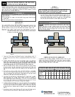
Страница 3: ...n at this point otherwise repeat Steps 6 and 7 NOTE 1 It is not necessary to re check tightening torque after equipment has been in operation 2 The torque capacity of these units can be increased by a...

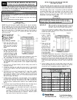
Страница 4: ...aft hub or coupling connection by means of a mechanical interference fit Please follow these INSTALLATION AND REMOVAL INSTRUCTIONS carefully to ensure proper performance of this B LOC unit WARNING Whe...

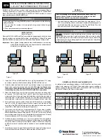
Страница 5: ...rn at this point otherwise repeat Steps 7 and 8 NOTES 1 It is not necessary to re check tightening torque after equipment has been in operation 2 In installations subjected to extreme corrosion the sl...

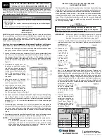
Страница 6: ...d torque Ma and check all locking screws No screw should turn at this point otherwise repeat Steps 7 and 8 NOTES 1 It is not necessary to re check tightening torque after equipment has been in operati...

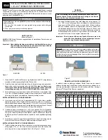
Страница 7: ...ler screws 8 Reset torque wrench to specified torque Ma and check all large locking screws and then reset torque wrench Ma and check all small locking screws No screw should turn at this point otherwi...

Страница 8: ...shaft are located approximately opposite the keyway In addition a locking screw should be centered directly over the keyway When tightening locking screws it is important to follow the installation p...

Страница 9: ...t least three 3 screws into push off threads in order to keep Parts 1 and 2 separated during assembly see Figure 2 3 After inserting Keyless Bushing into hub bore relocate locking screws used for sepa...

Страница 10: ...turns even if initially some locking screws require a very low tightening torque to achieve 1 4 turns for several passes until 1 4 turns can no longer be achieved 5 Continue to apply overtorque for 1...

Страница 11: ...set it approximately 5 higher than specified tightening torque Ma Tighten locking screws in either a clockwise or counterclockwise sequence using approx 1 4 i e 90 turns even if initially some locking...

Страница 12: ...respectively Hand tighten remaining locking screws 5 Use torque wrench and set it approximately 5 higher than specified tightening torque Ma Tighten locking screws in either a clockwise or counterclo...

Страница 13: ...out over torquing an infinite number of passes would be needed to reach specified tightening torque 6 Reset torque wrench to specified torque Ma and check all locking screws No screw should turn at th...

Страница 14: ...0 Reset torque wrench to specified torque Ma and check all locking screws No screw should turn at this point Otherwise repeat Steps 9 and 10 REMOVAL Refer to Figure 2 Prior to initiating the following...

Страница 15: ...components Loosen all locking screws in several stages by using approximately 1 2 turns following either a clockwise or counterclockwise sequence until the WK Rigid Coupling can be moved on the shafts...

Страница 16: ...respectively Hand tighten remaining locking screws 5 Use torque wrench and set it approximately 5 higher than specified tightening torque Ma Tighten locking screws in either a clockwise or counterclo...

Отзывы: