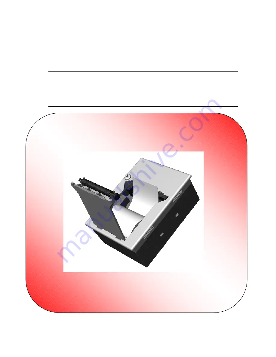
EPC1100 THERMAL PRINTER
Operation Manual - Version 1.0
July-2000
Страница 1: ...EPC1100 THERMAL PRINTER Operation Manual Version 1 0 July 2000...
Страница 2: ...FENIX IMVICO EPC1100 OPERATION MANUAL 2 37 Revision list for the EPC1100 thermal printer operation manual Date 11 07 2000 Page Type of revision Before change After change...
Страница 3: ...232 TTL 10 2 2 2 2 PARALLEL PORT CONNECTION CENTRONICS 11 2 3 INTERFACING WITH A PERSONAL COMPUTER 12 2 3 1 Parallel input output 12 2 3 2 Serial input output 14 3 BASIC OPERATIONS 17 3 1 LOADING PAP...
Страница 4: ...pin out 15 Fig 2 8 Serial input output signal timing chart 15 Fig 3 1 Loading paper 17 Fig 3 2 Accessing the self test button 18 Fig 3 3 Sample ticket 20 Fig 5 1 PC437 Standard Europe character table...
Страница 5: ...turn on Vcc first and then Vp When switching the power supply OFF turn off Vcc and Vp simultaneously or turn off Vp first and then Vcc When using two power supply lines a Vcc 5v line and a Vp 4 2 8 5...
Страница 6: ...medical instrumentation process control systems etc Main features of the EPC1100 printer are Easy maintenance structure Easy installation procedure Compact and lightweight Single 5V dc power supply H...
Страница 7: ...nter will be set Place the EPC1100 printer into the hole and push until the pieces marked with an A in Fig 2 1 make pressure enough to secure the EPC1100 to the surface Optionally two metric screws DI...
Страница 8: ...ply connector CON4 Communications connector Fig 2 2 EPC1100 connectors location 2 2 1 POWER SUPPLY CONNECTOR Attach power supply cable to connector CON1 Verify power supply voltage before making the c...
Страница 9: ...R COMMANDS N 64 dynamic division N 192 fixed division Vp Head driven voltage V Rh Head resistance Ohms 0 4 maximum current for driving the motor For example if VP VCC 5v dc N 64 and Rh Rank A 187 ohms...
Страница 10: ...P0 5 contacts 2 2 2 1 SERIAL PORT CONNECTION RS 232 TTL If you use the serial interface attach serial port cable to connector CON4 Terminal n Signal Name Function 1 2 3 4 5 6 7 8 9 10 11 12 13 14 15...
Страница 11: ...terface attach CENTRONICS cable to connector CON4 Terminal n Signal Name Function 1 STB In Strobe 2 DATA0 3 DATA1 4 DATA2 5 DATA3 6 DATA4 7 DATA5 8 DATA6 9 DATA7 In Data Bus 10 ACK Out Acknowledge 11...
Страница 12: ...pinout The busy and acknowledge signals are output every byte If 128 bytes have been stored in the EPC1100 input buffer the busy status continues until the amount of data stored in the input buffer be...
Страница 13: ...device When high is 1 and low is 0 the data on these lines are placed by the STROBE signal Busy BUSY output pin CON4 11 The BUSY signal indicates that the EPC1100 is ready to receive data When the BU...
Страница 14: ...The EPC1100 receives and checks serial data according to the transmission bauds programmed If the input data is not printed correctly the transmission conditions between the host device and the EPC110...
Страница 15: ...1 0 0 0 1 1 0 0 1 1 0 0 1 0 0 0 When 31H is sent and the buffer becomes full T1 typ 20uS T2 typ 20 uS 1 baud rate Fig 2 8 Serial input output signal timing chart EPC1100 SERIAL CONNECTOR PC RS 232 DB...
Страница 16: ...rogrammed transmission conditions Serial data input RXD input pin CON4 17 Data input port Data is input from the host device according to the programmed transmission conditions Serial busy RTS output...
Страница 17: ...ntinuously sent by serial output 3 1 LOADING PAPER This is one of the most advantageous features of the EPC1100 Due to the printer design and to the easy paper load capability of the printer mechanism...
Страница 18: ...he current baud setting and all available characters are printed when a test print is performed Through this function you can simply confirm the current baud setting and whether or not the EPC1100 pri...
Страница 19: ...e new values The EPC1100 can be reseted in two ways SOFTWARE Reset command ESC HARDWARE Switch the EPC1100 OFF and then switch it ON 3 2 2 HEXADECIMAL MODE Immediately after baud rate is programmed EP...
Страница 20: ...FENIX IMVICO EPC1100 OPERATION MANUAL 20 37 Fig 3 3 Sample ticket SELF TEST BAUD RATE SELECT HEXADECIMAL MODE...
Страница 21: ...0 reports the error sending the 68H code via TxD for the serial transmission and setting the CON4 PIN13 ERR to 0 for the parallel transmission This is a recoverable error The EPC1100 allows printing w...
Страница 22: ...0 printer is designed like a terminal that can recognize some software control codes There are some codes which perform the same action This allows compatibility with some popular printers Next figure...
Страница 23: ...e EPC1100 only performs a line feed operation when the line buffer is empty The amount of paper feed for one line is the amount of line spacing plus the character height which is set at that time Any...
Страница 24: ...n take on value from 20H to 7FH 4 to 127 dot line The default value for n is 16H 2 5mm ________________________________________________________________ ESC SP n CHARACTER SPACING _____________________...
Страница 25: ...mmand sets the characters new width despite of the previous state of the double width mode These commands do not affect the characters height __________________________________________________________...
Страница 26: ...ata is as follows Amount of image data nhx256 nl x48 bytes The data following nl and nh is printed out entirely as image data A bitmap picture may be considered like a bidimensional array of bits Each...
Страница 27: ...the number of graphics rows in binary format low byte n2 is the number of graphics rows in binary format high byte data are the bit image data to print For example if graphic data of A character is r...
Страница 28: ...n Hexadecimal codes 1B 73 n Function This control causes to transmit the next character received n The sequence ESC s A will not print character A but it will be transmitted in serial from the EPC1100...
Страница 29: ...ew width is 2 despite of the previous value of the X Scale Whenever double width mode is set to OFF the characters new width is 1 despite of the previous value of the X Scale These commands do not aff...
Страница 30: ...blocks are activated in groups The group of physical blocks is called a logical block For the EPC1100 either dynamic division or fixed division can be selected as the method of division for logical bl...
Страница 31: ...l as the first steps of the motor The make up of the logical blocks in the fixed division mode is in Fig 5 5 Number of logical blocks Maximum number Of activated dots Motor step 1 2 3 4 5 6 First Step...
Страница 32: ...3 n n dot line spacing ESC SP n 27 32 n 1B 20 n n char spacing ESC W n 27 87 n 1B 57 n toggle double W ESC w n 27 119 n 1B 77 n toggle double H ESC V n1 n2 27 86 n1 n2 1B 56 n1 n2 bit image graphics l...
Страница 33: ...__________ APPENDIX A SOFTWARE EXAMPLES ________________________________________________________________ FENIX IMVICO supplies some software examples showing the EPC1100 capabilities If you are intere...
Страница 34: ...v 2 8 A at 7 2v 3 A at 8v Vcc 20 mA Maximum in fixed division mode Vpp 5 7 A at 5v Dimensions WxDxH mm 95x52x128 Operating temperature 0 C to 50 C noncondensing Storage temperature 20 C to 60 C noncon...
Страница 35: ...100 XX nil standard type XX custom made type under agreement only All models are refereed to VP 5v dc If one other VP value is applied user must request a special microcontroller software version A di...
Страница 36: ...t no characters are printed Make sure you are using the correct paper Make sure you are using the correct side of the thermal paper Check your program If the paper is correct try to execute a self tes...
Страница 37: ...OPERATION MANUAL 37 37 ________________________________________________________________ APPENDIX E EPC1100 PHYSICAL DIMENSIONS ________________________________________________________________ All the...