background image

Functions and displays

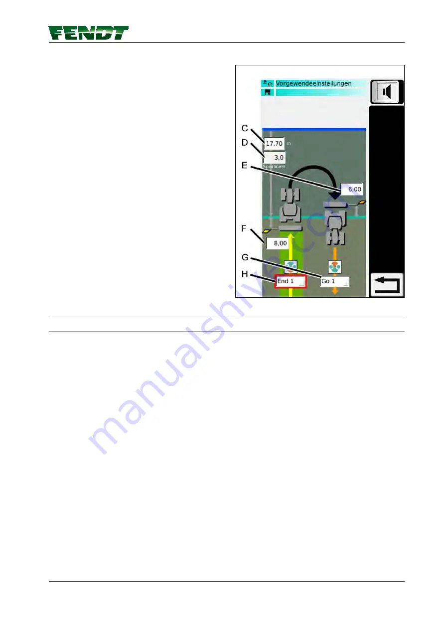
(C)

Headland length in meters

(D)

Calculated number of headland way-lines,

dependent on the way-line distance (no

setting!)

(E)

Setting (in meters) for "Driving into the field":

Distance to the headland boundary, where

the AutoTI/headland alarm is triggered

(F)

Setting (in meters) for "Driving out of the

field": Distance to the headland boundary,

where the AutoTI/headland alarm is triggered

(G)

Select the TeachIn sequence for "Driving into

the field"

(H)

Select the TeachIn sequence for "Driving out

of the field"

Here, the:
• Length of the headland,
• Desired TI sequence,
• Position at which the TI sequence or headland

alarm is triggered is set.

NOTE: 

Set before entering the values for the headland,

the working width and the way line distance.

Fig. 93  

7.16.2  Headland management TI/AutoTI

NOTE: 

Due to satellite drift, a field boundary recording and therefore the headland management/AutoTI

are only expedient from decimetre (DM) accuracy or with RTK (CM) accuracy.

7. Start-up

VarioGuide 

131

438.020.070.012

Содержание varioguide

Страница 1: ...VarioGuide Novatel VarioGuide Trimble Marktoberdorf AGCO GmbH Johann Georg Fendt Str 4 D 87616 Marktoberdorf FENDT is a worldwide brand of AGCO AGCO 2015 Original Operator s Manual November 2015 438 0...

Страница 2: ......

Страница 3: ...ny years of economic and trouble free operation You will find an overview of all maintenance operations in the maintenance schedule in this maintenance manual Maintenance and repair work should only b...

Страница 4: ...VarioGuide 438 020 070 012...

Страница 5: ...ractor Disclaimer AGCO Fendt accepts no responsibility or liability for damage to property injury to persons or death caused by improper or negligent use of its products including the VarioGuide syste...

Страница 6: ...form equipment or technology may be required at any time The details of delivery appearance technical data and functions of the machine is only correct at the time of going to press It may not be poss...

Страница 7: ...nce time 23 3 1 6 Conditions of use and application possibilities 23 3 1 7 Restrictions 23 3 1 8 Switch off limits 24 3 2 Specification 25 3 2 1 Topcon accuracy specifications 25 3 2 2 Trimble accurac...

Страница 8: ...lement 79 7 2 4 5 Set the center of the rear mounted implement 80 7 2 4 6 Set the trigger for the rear mounted implement 81 7 3 Save mounted implement data 82 7 3 1 Save implement on stopping 82 7 4 E...

Страница 9: ...receiver settings 109 7 10 4 1 xFill settings 109 7 11 Field Settings 111 7 11 1 Add field 111 7 11 2 Record field boundary 112 7 11 3 Record manage obstacles 115 7 12 Way line 119 7 12 1 Create and...

Страница 10: ...Table of contents VarioGuide 438 020 070 012...

Страница 11: ...1 Introduction 1 1 Delivery of VarioGuide system 13 1 2 OPERATOR S MANUAL FENDT VarioGuide 14 Table of contents VarioGuide 11 438 020 070 012...

Страница 12: ...Table of contents 12 VarioGuide 438 020 070 012...

Страница 13: ...e with regulations for the registration and use of radio signals System delivery and instructions on the VarioGuide track guidance system For further information and notes refer to the appropriate sec...

Страница 14: ...de This operator s manual is only valid in conjunction with the operator s manual for the tractor AGCO GmbH Maschinen und Schlepperfabrik 87616 Marktoberdorf Bavaria Germany www fendt com PSD AP 2015...

Страница 15: ...t prevention regulations 17 2 1 1 Marking of places that affect your safety 17 2 1 2 Advice for the operator 17 2 1 3 Safe operating environment 18 2 1 4 Switching off in an emergency situation 18 Tab...

Страница 16: ...Table of contents 16 VarioGuide 438 020 070 012...

Страница 17: ...at all times and have full control over the machine VarioGuide cannot detect obstacles such as persons or objects that are not defined and saved in the system While automatic steering is in operation...

Страница 18: ...rised national frequency ranges to avoid interference with other systems remote controlled cranes forestry cranes etc 2 1 4 Switching off in an emergency situation The operator can switch off the way...

Страница 19: ...ruption 23 3 1 4 Static and dynamic accuracy satellite drift 23 3 1 5 Convergence time 23 3 1 6 Conditions of use and application possibilities 23 3 1 7 Restrictions 23 3 1 8 Switch off limits 24 3 2...

Страница 20: ...Table of contents 20 VarioGuide 438 020 070 012...

Страница 21: ...ignals from at least four satellites simultaneously The four signal propagation times from the satellites to the receiving aerial are then calculated in the receiving device This is used to determine...

Страница 22: ...rs the tractor NOT the implement If the implement does not run concentrically to the tractor because it is being pulled downhill for example deviations in accuracy may occur Fig 5 The wave angle and t...

Страница 23: ...uracy Signal interruptions e g due to obstacles such as buildings or trees delay this process After an extended interruption in the correction signal the system loses the level of accuracy already ach...

Страница 24: ...s The range of the base station depends on the nature of the terrain and on the weather Accuracy decreases as the distance increases The tractor is too far away from the base station After an interrup...

Страница 25: ...res US Department of Defense deteriorations in operation ionospheric and tropospheric conditions satellite geometries length of the base line and multipath effects OmniSTAR VBS OmniSTAR HP WAAS and EG...

Страница 26: ...bject to GNSS system features US Department of Defense deteriorations in operation ionospheric and tropospheric conditions satellite geometries length of the base line and multipath effects RangePoint...

Страница 27: ...menu tree 29 4 2 VarioGuide info 31 4 3 Vario Guide Main Menu 32 4 4 Implement selection 34 4 5 Field Settings 36 4 6 Steering behavior 38 4 7 Signal settings 39 4 8 System info 40 Table of contents V...

Страница 28: ...Table of contents 28 VarioGuide 438 020 070 012...

Страница 29: ...4 1 VarioGuide menu tree Fig 1 4 Quick Start VarioGuide 29 438 020 070 012...

Страница 30: ...Fig 2 4 Quick Start 30 VarioGuide 438 020 070 012...

Страница 31: ...r on wayline F Correction signal and accuracy G Field Settings H AutoTI status Press each icon to move directly Quick Jump to the following pages A Implement Settings B Signal settings C Steering beha...

Страница 32: ...ngs page C Open Steering settings page D Open Signal settings page E Open Headland settings page F AutoTI activation H Jump back one menu level I Wayline adjustment J Manual offset to the left or righ...

Страница 33: ...Display A Current offset display B Display offset value for manual wayline offset C Overall offset display Fig 5 4 Quick Start VarioGuide 33 438 020 070 012...

Страница 34: ...ate new implement D Change front mounted implement settings F Change rear mounted implement settings G Change implement settings on second rear mounted implement H Jump back one menu level Fig 6 4 Qui...

Страница 35: ...istance C Calculated wayline distance display D Symbol Implement determines wayline guidance E Front mounted implement selection field F Symbol Implement is used for processed area G Rear mounted impl...

Страница 36: ...4 5 Field Settings Softkeys A Add field C Add boundary E Create way line G Add obstacle H Jump back one menu level I Popup wayline information Fig 8 4 Quick Start 36 VarioGuide 438 020 070 012...

Страница 37: ...Display A Manage fields pull down menu B Field boundary available yes no C Way line pull down menu D Obstacles pull down menu Fig 9 4 Quick Start VarioGuide 37 438 020 070 012...

Страница 38: ...4 6 Steering behavior H Back Fig 10 4 Quick Start 38 VarioGuide 438 020 070 012...

Страница 39: ...7 Signal settings A Correction signal B System info C Gyro compass D NMEA data interface NOTE Press the respective softkey to access the required page Fig 11 4 Quick Start VarioGuide 39 438 020 070 01...

Страница 40: ...sation has been successful Whenever the receiver has been switched on a short distance exceeding 1 5 km h must be driven to initialise the gyro compass see Note below D Steering system The green tick...

Страница 41: ...5 2 Display 45 5 2 1 Full screen 45 5 2 2 Zoom 46 5 2 3 Info bar 46 5 2 4 Steering status 47 5 2 5 Novatel bar indicator Trimble 47 5 3 Functions 49 5 3 1 Set markers 49 5 3 2 Marker settings 50 5 3 3...

Страница 42: ...Table of contents 42 VarioGuide 438 020 070 012...

Страница 43: ...differ from the system installed in the tractor NOTE To navigate to the main page press the softkey in the map view 5 1 2 Map view The map view shows the display functions from VarioDoc and VarioGuid...

Страница 44: ...Guide Mapping the processed area Position of the machine Target way line Way line distance Correction signal info Steering status NOTE Set trigger functions and implement width for area marker in Vari...

Страница 45: ...reen Fig 2 C Marker settings D Worked area settings F Road field mode NOTE In road mode the implement is not shown G Set markers H Change display size I Switch between 2D and 3D K Zoom 5 Map view Vari...

Страница 46: ...current way line deviation Mode 1 shows two direction arrows above the current way line orange arrow minor deviation orange and red arrow major deviation 0 00 Mode 2 is activated by selecting the tra...

Страница 47: ...ring is active Steering icon with a warning triangle on a white background A system fault has occurred 5 2 5 Novatel bar indicator Trimble NOTE Automatic wayline guidance can only be activated when at...

Страница 48: ...Bar indicato r GNSS Correction signal HDOP SV OK OK every over 3 bars OK OK every 1 5 6 OK OK every 1 3 7 5 Map view 48 VarioGuide 438 020 070 012...

Страница 49: ...the pop up shown below will appear Fig 5 2 Select marker color NOTE A number ID starting at 1 is also assigned for each individual marker color The name of the marker can be changed in the marker sett...

Страница 50: ...markers in this list Fig 7 5 3 3 Worked area settings Fig 8 A Worked areas Activate Deactivate The area colored green on the map shows the processed area This processed area is linked to the Trigger S...

Страница 51: ...oft key A or B to activate manual or automatic color selection A MAN AUTO softkey B Manual color selection softkey C Delete the area marker in the current field Fig 10 Delete the area marker in the cu...

Страница 52: ...A to change between manual and automatic color display I is the setting for the number of normal colored waylines between two contrasting waylines Soft key J for contrast color selection K is the sett...

Страница 53: ...6 VarioGuide components and calibrations 6 1 Calibrations 55 6 1 1 Calibrate steering angle sensor and steering valve 55 Table of contents VarioGuide 53 438 020 070 012...

Страница 54: ...Table of contents 54 VarioGuide 438 020 070 012...

Страница 55: ...ight along the way lines Other steering problems e g tractor begins to sway occur NOTE If required calibrate the front axle suspension please speak to your Fendt dealer Calibrating the steering angle...

Страница 56: ...edly until the symbol A flashes Confirm with RETURN Fig 4 Input code 2401 Press one of the buttons until the desired number is displayed Confirm with RETURN Fig 5 Turn steering wheel against the left...

Страница 57: ...rm with RETURN Fig 8 If calibration is completed without errors O K appears and the new sensor settings are saved NOTE Settings are only stored when ignition key has been turned to 0 position Wait for...

Страница 58: ...lection of the front wheels Risk of injury and death Material damage is possible During calibration check that there are no people or objects within the steering area NOTE During calibration the valve...

Страница 59: ...e multiple display Fig 12 Press one of the buttons repeatedly until the symbol A flashes Confirm with RETURN Fig 13 Press one of the buttons repeatedly until the symbol A flashes Confirm with RETURN F...

Страница 60: ...ion is completed without errors O K appears and the new sensor settings are saved NOTE Settings are only stored when ignition key has been turned to 0 position Wait for at least 30 seconds before swit...

Страница 61: ...teering to left F07 No movement in direction steering to right F08 Calibration taking too long F09 User terminated calibration with ESC F11 Plausibility Signal in direction steering to left F12 Plausi...

Страница 62: ...6 VarioGuide components and calibrations 62 VarioGuide 438 020 070 012...

Страница 63: ...rear mounted implement 81 7 3 Save mounted implement data 82 7 3 1 Save implement on stopping 82 7 4 Exchange implement data and field data 84 7 4 1 Plug in the USB stick and call up data exchange 84...

Страница 64: ...dem correction signal 108 7 10 4 Trimble receiver settings 109 7 10 4 1 xFill settings 109 7 11 Field Settings 111 7 11 1 Add field 111 7 11 2 Record field boundary 112 7 11 3 Record manage obstacles...

Страница 65: ...been created and to add the settings in the VarioGuide implement settings and way line distance A new implement can also be created Call up the management main menu 7 Applications main menu The view s...

Страница 66: ...and way line distance A new implement can also be created Call up the management main menu 10 4 terminal Information management D Management 2011 35 10 10 11 10 24 Verwaltung Info D Fig 4 Load implem...

Страница 67: ...info press the soft key for the on board computer On board computer page is displayed 3 On the On board computer page press the soft key for the trigger settings Trigger settings page is displayed 4...

Страница 68: ...the VarioDoc Main Page appears 2 In VarioDoc Main Page press the soft key for the on board computer the On board computer page is displayed 3 On the On board computer page press the trigger settings t...

Страница 69: ...d implement 7 2 3 1 Install front mounted implement Procedure 1 Press softkey A A pop up appears Fig 9 2 Select front mounted implement Ger teanbauposition ausw hlen Heck Fig 10 7 Start up VarioGuide...

Страница 70: ...cessing area of the implement from the lower link hooks Procedure 1 Start work and drive approx 10 m 2 Measure the processed width working width 3 Measure the length between the navigation point of th...

Страница 71: ...of the front mounted implement Procedure 1 Select the working width field A by touch or via the external control panel 2 Set the processed width value via the external control panel Fig 12 7 Start up...

Страница 72: ...the front mounted implement Procedure 1 Select the navigation point field A by touch or via the external control panel 2 Set the navigation point distance via the external control panel Fig 13 7 Star...

Страница 73: ...r the front mounted implement Procedure 1 Select the coupling length field A by touch or with the external control panel 2 Set the coupling length distance via the external control panel Fig 14 7 Star...

Страница 74: ...Procedure 1 Select the center field A by touch or via the external control panel 2 Set the center via the external control panel NOTE Only set the center if the mounted implement deviates from the ce...

Страница 75: ...f toggle switch A is set to I the distance and area are always measured except when the on board computer is paused The other buttons are grayed out If toggle switch A is set to AUTO the distance and...

Страница 76: ...implement 7 2 4 1 Install rear mounted implement Procedure 1 Press softkey A A pop up appears Fig 17 2 Select the rear mounted implement Ger teanbauposition ausw hlen Heck Fig 18 7 Start up 76 VarioGu...

Страница 77: ...n point distance and coupling length Working width Center Navigation point Coupling length Actual working width of the implement Movement of the implement from the center e g for mowers Distance of th...

Страница 78: ...ength between the start of the processed area and the attachment hook of the front power lift NOTE If the mark is to be created at the end of the implement measure from this point to the end of the im...

Страница 79: ...r the rear mounted implement Procedure 1 Select the coupling length field A by touch or with the external control panel 2 Set the coupling length distance via the external control panel Fig 22 7 Start...

Страница 80: ...Procedure 1 Select the center field A by touch or via the external control panel 2 Set the center via the external control panel NOTE Only set the center if the mounted implement deviates from the ce...

Страница 81: ...If toggle switch A is set to I the distance and area are always measured except when the on board computer is paused The other buttons are grayed out If toggle switch A is set to AUTO the distance and...

Страница 82: ...ide Save the current implement settings with the same name If an implement has been loaded and one or more settings then changed the page shown opposite appears when the engine is switched off The cur...

Страница 83: ...d confirm Fig 27 To save the current implement settings with a new name select a blank line specify a name using the keyboard and confirm The terminal then switches off NOTE This procedure is used to...

Страница 84: ...e replacing the terminal 7 4 1 1 Insert USB stick Procedure 1 Pull flap A open to reveal the USB ports 2 Insert USB stick into the appropriate port Fig 29 7 4 1 2 Call up data exchange on 10 4 2011 35...

Страница 85: ...lect and transfer individual data Procedure 1 Using the soft key select the data to be transferred A Field data B Implement data 2 Select field data or implement data by touch or with the external con...

Страница 86: ...he transfer of field data a popup appears and asks whether processed areas should be transferred as well If so the transfer process may take a few minutes NOTE The transferred data can then be seen in...

Страница 87: ...NOTE Before the transfer of field data a popup appears and asks whether processed areas should be transferred as well If so the transfer process may take a few minutes NOTE The transferred data can th...

Страница 88: ...l control panel H B A Fig 35 3 Press the soft key J individual data is transferred from the USB stick to the terminal NOTE If there is identical data on the terminal a popup appears and asks whether t...

Страница 89: ...A Fig 37 2 Press the soft key L all data is transferred from the USB stick to the terminal NOTE If there is identical data on the terminal a popup appears and asks whether the existing file should be...

Страница 90: ...ternal mobile radio modem NovAtel SMART6 L Sub meter Autonomous EGNOS WAAS Centimeter RTK base SATEL EASy Proof radio modem External radio modem RTK network Internal GSM GPRS modem External mobile rad...

Страница 91: ...r 7 6 1 Autonomous NOTE The position is determined without correction signals using only GPS and GLONASS satellites for regions in which there is no correction signal or none can be received Fig 39 7...

Страница 92: ...s taken to receive the correction signal update If 999 is shown here the correction signal cannot be currently received Connection status Specifies the connection status of the GNSS receiver to the so...

Страница 93: ...installed receiver Signal type The correction signal source can be selected here Base Type Fendt Base Accuracy Bar indicator and decimal value of static accuracy Signal lag Specifies the time in s ta...

Страница 94: ...kHz with 6 25 kHz spacing Error correction Set the error correction here ON OFF Signal format Select the signal format CMR RTCM 2 3 RTCM 3 1 7 7 1 2 Fallback FENDT base station Procedure Press toggle...

Страница 95: ...tion signal source can be selected here Base Type External station Accuracy Bar indicator and decimal value of static accuracy Signal lag Specifies the time in s taken to receive the correction signal...

Страница 96: ...this function allows wayline guidance to a lower degree of accuracy Fig 44 7 7 3 RTK network internal mobile radio modem 7 7 3 1 Configure the internal mobile modem correction signal NOTE After the ig...

Страница 97: ...strength Accuracy Bar indicator and decimal value of static accuracy Signal lag Specifies the time in s taken to receive the correction signal update If 999 is shown here the correction signal cannot...

Страница 98: ...acy Fig 46 7 7 4 RTK network external mobile radio modem 7 7 4 1 Configure the external mobile modem correction signal NOTE After the ignition has been switched OFF ON the system connects to the GSM G...

Страница 99: ...pecifies the time in s taken to receive the correction signal update If 999 is shown here the correction signal cannot be currently received Connection status Specifies the connection status of the GN...

Страница 100: ...omous Autonomous Trimble AG 382 NOTE The position is determined without correction signals using only GPS and GLONASS satellites for regions in which there is no correction signal or none can be recei...

Страница 101: ...s taken to receive the correction signal update If 999 is shown here the correction signal cannot be currently received Connection status Specifies the connection status of the GNSS receiver to the so...

Страница 102: ...gnal update If 999 is shown here the correction signal cannot be currently received Connection status Specifies the connection status of the GNSS receiver to the source of the correction data e g conn...

Страница 103: ...ion of the installed receiver Signal type The correction signal source can be selected here RTX type The RTX type can be selected here RTX Standard RTX Fast EU RTX Fast US Frequency Baud rate Accuracy...

Страница 104: ...Baud Central USA RTXCN 1557 8150 MHz 2400 Baud East USA RTXEN 1557 8590 MHz 600 Baud Canada and South Central America RTXSA 1539 8325 MHz 600 Baud Europe RTX Fast RTXEU 1529 7250 MHz 2400 Baud Europe...

Страница 105: ...eceiver Signal type The correction signal source can be selected here Base Type Fendt Base Accuracy Bar indicator and decimal value of static accuracy Signal lag Specifies the time in s taken to recei...

Страница 106: ...isplay Satellite receiver Designation of the installed receiver Signal type The correction signal source can be selected here Base Type Fendt Base Accuracy Bar indicator and decimal value of static ac...

Страница 107: ...ed off Please note that this action may result in data charges Set correction signal 1 Select the correction signal via the Signal Type selection field 2 Select Internal Modem as the modem type 3 Sele...

Страница 108: ...pending on the hardware modules installed in the receiver Signal format w 7 10 3 RTK network external mobile radio modem 7 10 3 1 Configure the external mobile modem correction signal NOTE After the i...

Страница 109: ...tatus Specifies the connection status of the GNSS receiver to the source of the correction data e g connected update required expired The tick shows whether the GNSS receiver is currently connected to...

Страница 110: ...elected here RTX Standard RTX Fast EU RTX Fast US Baud rate Regional settings Region Frequency Baud rate West USA 1557 8615 MHz 600 Baud Central USA 1557 8150 MHz 2400 Baud East USA 1557 8590 MHz 600...

Страница 111: ...7 11 1 Add field Procedure 1 Press the soft key A the pop up for inputting the field name appears Fig 58 2 Input the field name and confirm with the pop up will then close Fig 59 7 Start up VarioGuide...

Страница 112: ...hin the selected field the pop up below will appear Fig 60 2 Overwrite field boundary or abandon operation Press soft key current field boundary will be overwritten Press soft key pop up will be close...

Страница 113: ...3 Select recording page 4 Confirm using pop up will close Fig 62 Start boundary recording 5 Press soft key C boundary recording will be activated Fig 63 7 Start up VarioGuide 113 438 020 070 012...

Страница 114: ...differently in the corners for a more accurate approximation of the boundaries recording may be paused and later restarted 7 Press soft key C once more boundary recording will resume Fig 64 Quit boun...

Страница 115: ...e has been selected in the pop up above In addition a field can be selected and the obstacle name assigned Fig 67 Large obstacle Select the recording page The image shown opposite appears once large o...

Страница 116: ...pears with modified softkey G drive around the large obstacle NOTE Large obstacles are recorded in the same way as boundaries Fig 69 End and save the area recording To end the area recording press sof...

Страница 117: ...A field can be selected and the obstacle name assigned Manage obstacles The pop up shown opposite appears once softkey K has been pressed Fig 71 7 Start up VarioGuide 117 438 020 070 012...

Страница 118: ...From this pop up obstacles can be selected renamed and deleted 7 Start up 118 VarioGuide 438 020 070 012...

Страница 119: ...rioGuide information page the VarioGuide main page and the Field settings page see chapter 4 1 VarioGuide menu tree page 29 NOTE Before creating a wayline specify a field name and record a boundary if...

Страница 120: ...al If you press this a value will appear indicating the minimum distance that must be driven before button B appears and can be pressed The wayline can be saved with a freely selectable name More than...

Страница 121: ...ar in the terminal followed by PAUSE and STOP after START has been pressed Recording is interrupted by pressing PAUSE and resumed by pressing CONTINUE Recording flashes to indicate that the system is...

Страница 122: ...Fig 80 Fig 81 7 Start up 122 VarioGuide 438 020 070 012...

Страница 123: ...manner as the contour The circular arc driven is used to calculate the theoretical accuracy of the center of the circle If this is less than 10 00 m the STOP button will appear E START softkey Fig 83...

Страница 124: ...way line distance Procedure 1 Set working width of the implement in A 2 Set overlap B NOTE Way line distance C is calculated Way line distance implement width minus overlap Fig 86 A Working width dis...

Страница 125: ...green tick will appear once initialisation has been successful Whenever the receiver has been switched on a short distance exceeding 1 5 km h must be driven to initialise the gyro compass see Note bel...

Страница 126: ...ment and no stand by time has been set thus resulting in the receiver being switched off a short distance must be driven at a speed exceeding 1 5 km h until the green tick appears at C to initialize t...

Страница 127: ...ion conditions are satisfied see above System info the LED will change from a flashing to a steady light The steering status icon in map view and on the VarioGuide information page will also turn gree...

Страница 128: ...nnot be selected while automatic way line guidance is active Manual way line offset D If the tractor diverges too far from the way line e g on a slope the way lines can be moved to the right or left w...

Страница 129: ...e headland settings are only appropriate from decimetre DM accuracy or with RTK CM accuracy Softkeys E Headland settings F AutoTI pre activation only possible within a field boundary NOTE Only possibl...

Страница 130: ...Headland settings softkeys A Headland alarm ON OFF NOTE When you use AutoTI the alarm automatically switches on Fig 91 Select Variotronic TI sequence Fig 92 7 Start up 130 VarioGuide 438 020 070 012...

Страница 131: ...G Select the TeachIn sequence for Driving into the field H Select the TeachIn sequence for Driving out of the field Here the Length of the headland Desired TI sequence Position at which the TI sequenc...

Страница 132: ...ettings 4 The tractor is located within the recorded field boundary 5 AutoTI pre activation softkey F is activated can only be activated within the recorded field boundary Driving into the field 1 Dri...

Страница 133: ...r to the tractor receiver using a modem The VarioGuide receiver processes both signals position signal and correction signal so determining very precise location data NOTE A base station with a radio...

Страница 134: ...Mains cable Fig 97 Power supply unit Fig 98 SAE connecting cable current supply to base station Fig 99 SAE connecting cable alligator clips Fig 100 7 Start up 134 VarioGuide 438 020 070 012...

Страница 135: ...SAE connecting cable cigarette lighter Fig 101 SAE extension cord Fig 102 Serial connecting cable Fig 103 Null modem DB9 M M adapter Fig 104 7 Start up VarioGuide 135 438 020 070 012...

Страница 136: ...n C RS 232 communication interface A D RS 232 communication interface D E USB communication interface F Current supply connector Input Operation 6 28 VDC Load 9 28 VDC power consumption 2A G Modem sta...

Страница 137: ...satellites Flashing green Receiver is switched on and receiving satellites one flash per received GPS satellite Flashing orange Receiver is switched on and receiving satellites one flash per received...

Страница 138: ...I To switch from ON mode to STAND BY mode 1 Press and hold down ON OFF button A 2 LEDs K and J will turn green and then go out 3 Release ON OFF button A To switch from STAND BY mode to ON mode press t...

Страница 139: ...I 7 17 7 Set the base station channel on the tractor Procedure 1 Press soft key B 2 Follow on screen instructions Fig 110 3 Connect cable on the base station communication A or D connect to port C or...

Страница 140: ...top right C pillar serial interface use null modem DB9 M M adapter Fig 112 5 Confirm connection Fig 113 6 Transmission of base station configuration to the tractor 7 Close window using Fig 114 7 Star...

Страница 141: ...ocedure Connect cables 2 3 4 to the battery Fig 115 1 Base station 2 Current supply cable for base station 3 SAE connecting cable current supply to base station 4 SAE connecting cable alligator clips...

Страница 142: ...7 Start up 142 VarioGuide 438 020 070 012...

Страница 143: ...8 Faults and remedy 8 1 Fault diagnostics 145 8 1 1 Problems and possible remedial action 145 Table of contents VarioGuide 143 438 020 070 012...

Страница 144: ...Table of contents 144 VarioGuide 438 020 070 012...

Страница 145: ...ctor was too far from the required way line The distance from the required way line is greater than 10 m Drive the tractor closer to the required way line before activating way line guidance The autom...

Страница 146: ...fo see chapter 7 13 1 Check system info system status page 125 Contact your FENDT dealer Movements of the trailer coupling or the linkage drawbar allow lateral movement of the implement during operati...

Страница 147: ...atus page 125 Order a new correction signal license from OmniSTAR Contact your Fendt dealer The license for receiving the OmniSTAR correction signal has expired The expiry date is shown as having been...

Страница 148: ...tem info see chapter 7 13 1 Check system info system status page 125 xref href T003398 OmniSTAR has not sent full data for correction signal license A red cross appears in field B of System info see c...

Страница 149: ...9 Appendix 9 1 Glossary 151 9 1 1 Glossary 151 Table of contents VarioGuide 149 438 020 070 012...

Страница 150: ...Table of contents 150 VarioGuide 438 020 070 012...

Страница 151: ...olutions lie A CEP measurement of 50 shows that half of the measured position solutions lie within the radius of accuracy Controlled Traffic Farming CTF A method of agriculture that uses permanent tra...

Страница 152: ...nals received from pseudolites GPRS General Packet Radio Service Packet oriented service for transmission of data in GSM and UMTS networks GPS Global Positioning System North American NAVSTAR satellit...

Страница 153: ...the front to the rear section of the tractor For example the rise and fall of the tractor s engine cover due to changes in terrain NMEA National Marine Electronics Association Ntrip Networked Transpor...

Страница 154: ...number allocated to the respective GNSS satellite Cross track Xtrack The right angled distance between the current tractor position and the wayline Wayline offset The offset of the way line parallel...

Страница 155: ...ypoint One of the two reference points in the field used to define a virtual straight line the wayline Xtrack The right angled distance between the current tractor position and the wayline cross track...

Страница 156: ...9 Appendix 156 VarioGuide 438 020 070 012...

Страница 157: ......

Страница 158: ...AGCO Corporation 2015 All rights reserved 438 020 070 012 English November 2015...

Отзывы: