background image

Stages: 

Stages Types and Accessories

7-4

EUCENTRIC POSITION 

This should be adjusted after loading any new sample (other than wafer) 
or for the greatest accuracy, as the sample loading procedure clears all 
position informations. At the eucentric position, one can use various 
system components (such as the EDX) in a safe and optimal way. 

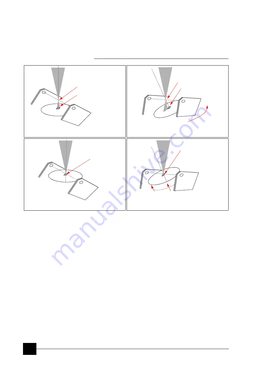
FIGURE 7-5

EUCENTRIC POSITION PRINCIPLE  

At the eucentric position the stage tilt and the electron beam axes 
intersect. When the stage is tilted or rotated in any direction, this point 
remains focused and almost does not shift. 

Finding Eucentric Position Procedure 

1.

Apply the 

Stage

 menu


Auto Beam Shift


Zero

 function. 

2.

Display the 

Window

 menu / 

Center Cross

 (

Shift + F5

). 

3.

Focus an image. 

Link Z to FWD

 and go to 10 mm WD. 

4.

Set stage tilt to 0°. 

5.

Using the Z-control, coarsely focus the image. 

6.

Set the magnification to 1000×, find a recognizable feature and 
center it under the yellow cross by moving the stage.

7.

Watching the feature, change the stage tilt to 15°. Using the Z-
control, bring the feature back under the cross.

8.

Change the stage tilt again to 30°, and bring the same feature back 
under the cross using the Z-control.

9.

Change the tilt to 0°. The feature should not shift significantly. If the 
shift is > 5 µm, repeat steps 6 to 9.

Note:


Described eucentric position procedure is valid for 50 mm stages. 

3)

 Tilting the stage does not move the point of interest out 

of the beam. 

1)

 The point of interest is focused below the Eucentric 

point (see 2). 

Eucentric position 

Tilt 

Eucentric position

Z adjustment 

Stage

Stage

2)

 Tilting the stage moves the point of interest out of the 

beam. 

Stage

Beam

Beam

Beam

Point of interest 

Point of interest 

Eucentric position 
and Point of interest 

Feature is at 
eucentric position.

Stage

Beam

1)

 The point of interest is focused at the Eucentric point 

(see 4). 

Содержание Quanta FEG 250

Страница 1: ...The Quanta FEG 250 450 650 User Operation Manual 5th Edition 20 August 2010 Copyright 2010 FEI Company All rights reserved...

Страница 2: ...Systems Incorporated Microsoft is a registered trademark of Microsoft Corporation Windows XP is a trademark of Microsoft Corporation Production Acknowledgments This manual was produced using FrameMake...

Страница 3: ...em 3 2 Vacuum Statuses 3 3 Pump button 3 3 Vent button 3 3 Vacuum Modes 3 4 High Vacuum HiVac Mode 3 4 Low Vacuum LoVac and ESEM Modes 3 4 Quanta FEG System States 3 7 Power Off 3 9 Chapter 4 Software...

Страница 4: ...on Screen 5 7 Optimising an Image 5 7 Principles of SEM imaging 5 7 Magnification 5 7 Scan Speed and Filtering 5 8 Contrast and Brightness 5 9 Focusing 5 10 Correcting Astigmatism 5 10 Pressure and W...

Страница 5: ...es Types and Accessories 7 2 Quanta FEG 250 50 mm Stage 7 2 Quanta FEG 450 650 100 150 mm Stage 7 3 Eucentric Position 7 4 Stage movement limits 7 6 Software Stage Functions 7 7 Map tab 7 7 Coordinate...

Страница 6: ...9 7 In Column Detector iCD 9 8 Retractable Detectors Control 9 8 Scanning Transmission Electrons Microscopy Detector STEM I 9 9 Annular Scanning Transmission Electrons Microscopy Detector STEM II 9 1...

Страница 7: ...i 9 57 Sample preparation 9 57 Image acquisition 9 58 Recommended settings 9 59 Symmetrical Low Vacuum Detector SLVD 9 60 Mapping tool 9 61 Image Analysis 9 62 Measurement Accuracy Verification 9 62 R...

Страница 8: ...C vi...

Страница 9: ...ves the basics about the vacuum system and procedures for several system on off modes including Log On Off Standby Mode Overnight Mode Complete Shutdown and Emergency Shutdown 4 SOFTWARE CONTROL descr...

Страница 10: ...g explanatory ones are also listed Major headings have been hung in the left column to help you scan for the basics within a chapter That column provides space for some explanatory figures and for you...

Страница 11: ...nd selectable energy Lens system The beam enters the lens system consisting of several electromagnetic lenses and exits to hit the specimen surface Scan unit The scan generator signal fed to the defle...

Страница 12: ...10 to 2600 Pa 0 1 to 20 Torr with auxiliary gas up to 4000 Pa 30 Torr Either mode can use water vapours from a built in water reservoir or an auxiliary gas which is supplied by the user and connected...

Страница 13: ...g point on the specimen Magnification is the ratio of the size of the viewing monitor screen to the size of the area scanned on the specimen Increased magnification is achieved by reducing the size of...

Страница 14: ...and output magnification pressure etc All user account levels created via FEI User Management software ensure for the particular users admission to both the operating system Windows XP and the xT mic...

Страница 15: ...and allows the interface and communication with the microscope controller Most of the functions are activated via the software control FIGURE 2 4 SYSTEM CONTROL PANEL POWER BUTTON Stage Controls The s...

Страница 16: ...vements see Chapter 6 FIGURE 2 6 FINAL LENS APERTURE STRIP CONTROL KNOB WARNING Aligning the final lens aperture is a mechanical process It is possible to misalign the aperture strip and obscure the b...

Страница 17: ...les up to 1500 C This option includes two 1500 C and one 1000 C heating stages The Cooling Heating Stage control kit The Feed through Port Relocator 52 pin Electrical Feed through 7 pin Electrical Fee...

Страница 18: ...trons heading nearly parallel to a surface which accentuates a surface roughness The WDX Completion Kit relocates the GSED detector connector bracket and GSED pre amplifier bias feed through to anothe...

Страница 19: ...ibes The Quanta FEG vacuum system Vacuum status and relevant actions Pump Vent Vacuum modes and relevant actions HiVac LoVac ESEM Quanta FEG System States Start up procedure generally Shut down proced...

Страница 20: ...ired for the given mode HiVac LoVac ESEM All valve and pump operations are fully automatic FIGURE 3 1 THE QUANTA FEG VACUUM SYSTEM Legend ABV Auxiliary Bypass Valve AGV Auxiliary Gas Valve BPV By Pass...

Страница 21: ...defined in the Preferences ESEM dialogue When the Pump button is clicked and the status is Transition venting the venting procedure stops and the system immediately starts to pump to the actually sel...

Страница 22: ...m mode Vented status by selecting an appropriate mode radio button the system prompts the user with the PLA Configuration dialogue this happens only for the first time after a particular Vent procedur...

Страница 23: ...ir needs to be filled see Chapter 8 the gaseous environment supplied by the user via the Auxiliary inlet placed on the back of the console Caution Maximum overpressure for Auxiliary gas and Nitrogen i...

Страница 24: ...em is pumping to the LoVac ESEM mode from the vented status in the LoVac ESEM mode and the gas type is changed in the LoVac ESEM mode and the Purge button is pressed There may be certain applications...

Страница 25: ...roscope console a compressed air and a nitrogen inlet optional for venting and cooling Interlocks prevent the vacuum system from operating if any of these are not present with the exception of nitroge...

Страница 26: ...on or for service actions like repair to essential systems electrical and air supplies e Switching off the console when Emitter is On is not optimal and sparing way for the emitter User should use the...

Страница 27: ...S S1 at the cabinet back which is placed at the very right side in the row FIGURE 3 2 MAINS SWITCH BOARD If this is not easily accessible 3 Turn off the mains wall switch if present and or disconnect...

Страница 28: ...System Operation Quanta FEG System States 3 10...

Страница 29: ...e the specific features The software interface controls most system functions including imaging image and movie gathering manipulation output detection and analysis stage and pressure OTHER SOFTWARE A...

Страница 30: ...ns contain pull down menus that display grouped listings of available commands or settings Some menu items are shown in grey and cannot be selected because of the system immediate condition Pull down...

Страница 31: ...settings need to be changed LIST BOXES contain available choices such as screen resolution magnification settings etc Click the List box to roll down a list of available values then click the desired...

Страница 32: ...inear response like the small adjuster placed below the exponential one has Its button position always corresponds to the actual parameter value within an available range Preset Adjuster This kind of...

Страница 33: ...e considered 2D control use These remembered values are used to estimate new values which have not been remembered yet The menu may contain less or some other functions that are actually available for...

Страница 34: ...Control software services During a transition between these states STARTING or STOPPING is displayed Some Microscope module buttons change its label and behaviour depending on the actual state The Sta...

Страница 35: ...itle bar labels the application 2 The Menu bar contains all operation menus and submenus 3 The Toolbar contains functional icons for the most frequently used microscope controls and for the fast acces...

Страница 36: ...title in the following text The File Menu Alt F opens File menu administrative functions Open displays a standard dialogue for opening images previously stored to a media Supported file formats are TI...

Страница 37: ...clearing an appropriate check box The settings is remembered per quad and used for the subsequent Save actions Save All Ctrl Shift S opens common dialogue for saving images from each quad providing an...

Страница 38: ...ftware the actual user is automatically logged off first and leaves the user in the operating system environment xT microscope Server is still running and controls the microscope in operation The Edit...

Страница 39: ...nge preset parameters These presets could be Exported Imported with the use of appropriate buttons The functionality is available only if activated in the Preferences General tab Note Holding the Shif...

Страница 40: ...scan value see the Preferences Scanning tab When either of the two presets are active or selected the respective icon is highlighted Slower Faster Scan Ctrl sets the scanning condition to the next pre...

Страница 41: ...ghtly charging specimens Note Clicking the down arrow next to the icon displays menu items Live Average Integrate Number of Frames enabling to select number of averaged or integrated images depending...

Страница 42: ...the active quad By rotating the circle a different viewing orientation of the sample area can be achieved by a physical stage rotation and adjustment of X and Y axes Stage rotation keeps the observed...

Страница 43: ...s the stage movement and displays Touch Alarm warning dialogue whenever the stage or a conductive specimen touches the objective lens or any other equipment conductively connected to the chamber This...

Страница 44: ...of the active quad image and stores their minimum and maximum Next time the ACB function is used it attempts to set the Contrast and Brightness so that the resulting image gray levels lies between th...

Страница 45: ...Image Enhancement module Process tab setting see below Lab Notes opens the Windows Notepad application over the quad 4 for the user to make immediate notes and remarks The Lab Notes can be used to ope...

Страница 46: ...working distance and with the first focusing Only Supervisor is allowed to change the marker position by double clicking a new position and by confirming this action in the popped up dialogue Crossha...

Страница 47: ...e sample area taken with different detectors or scan properties The Help Menu Alt H opens the Help menu and system informations functions Documentation F1 The Help window shows complete User Manual in...

Страница 48: ...efined as the actual electron beam diameter on the specimen surface and it is expressed by a relative number see Chapter 5 The optional way representable in the toolbar to the Spot size number is the...

Страница 49: ...astigmatism correction Beam Shift magnification change coarse fine active zoom in out Lens Alignment Scan Compucentric Rotation XY move get or tracking mode CCD imaging option place 5 mm Marker Compuc...

Страница 50: ...ing electron microscopes used for observing conductive specimens that can withstand low pressure conditions and do not outgas In this mode the system pumps continuously to achieve the lowest possible...

Страница 51: ...agnification HFW Module The continuous adjuster offers a variety of ways to control the actual imaging magnification see above The magnification range changes dynamically according to the working dist...

Страница 52: ...ocuses the image in a narrow range to facilitate the process Try to bring the rotation center to the screen center if the magnification is too high the rotation could seem like a linear motion instead...

Страница 53: ...emitted from the source The Coulomb Tube Current shows the electron current flowing above the final lens aperture The system conditions are displayed by means of the icons TABLE 4 2 STATUS ICON MEANI...

Страница 54: ...n tab helps to navigate across the sample surface Note The stage movement can be aborted by hitting the keyboard Esc key Don t hesitate to do so if you are not sure that the initiated movement is safe...

Страница 55: ...tion Module combines tools for measuring and making annotations in electron images A measurement tool an annotation shape or a text label can be selected from the first three icons on top of the modul...

Страница 56: ...used or loaded image including an optical one see Chapter 5 FIGURE 4 14 THE ENHANCED IMAGE MODULE 14 The Alignments Module contains alignments which enable to optimize the system performance see Chapt...

Страница 57: ...allows changing and presetting conditions for a group of the related functions Only one tab can be opened at any time The items chosen and changed from any of the preferences tab dialogues remain vali...

Страница 58: ...st contains items that are displayed in the Databar The items in the Selected list can be Moved Up Moved Down Top or Bottom according to priority or preference This in turn changes the order of the di...

Страница 59: ...s the captured image bit depth Drift Correction Yes No corrects imaging drifting when averaging filter is active When activated the text below the blinking quad pause icon notifies an user Continuous...

Страница 60: ...t below the respective title The new value replaces the selected one and is immediately sorted into the list The number of entries in the list remains fixed FIGURE 4 18 PRESETS PREFERENCES The High Vo...

Страница 61: ...values are the same as in Automatic mode The Purge button enables to start the purging using the actual Purge Mode and Settings manually when the system is already pumped to ESEM Low Vacuum otherwise...

Страница 62: ...ree groups Selecting appropriate group from the Category drop down list will display in the below property editor only the items belonging to this group Selecting Category All will display all items a...

Страница 63: ...acquisition has actually stopped Display Recording Movie message No 1 second 2 seconds 5 seconds 30 seconds At the beginning of the movie recording this message could be displayed in the recorded qua...

Страница 64: ...hift when the user requires very small point to point movements double click in the image at high magnifications Blank beam during long stage moves Yes No If Yes is selected the electron beam is autom...

Страница 65: ...dled The Active view the databar magnification value depends on whether the Single or Quad UI imaging mode is selected It is displayed in the databar and stored printed with an image with an icon repr...

Страница 66: ...ment software CONTROL POSSIBILITIES Context menu You can reach some context options by right clicking see below Press and Drag actions Instead of using menu options you can sometimes simply press and...

Страница 67: ...he user must be highlighted first If an FEI Microscope User has user data the account administrator is warned that user data will be removed also If any additional user is to be removed that additiona...

Страница 68: ...g provides an explanation of icons used in the tree About displays the FEI User Management software version and copyright ACCOUNT LOGGING This accounting utility monitors user log on off actions sessi...

Страница 69: ...Shift click 1 Activates Beam Shift hand cursor 2 Pauses Activates all quads when clicking the toolbar pause icon Right click To focus press and move the mouse to the left or right double ended arrow c...

Страница 70: ...approximately 40 80 of the field of view in any direction by clicking the appropriate keyboard Arrow key Alt or F10 Activates menu of the active application Pressing the underlined character in the me...

Страница 71: ...s Reduced Area Full Frame Mode Ctrl Shift F7 Starts Undo Image Post Processing F8 Degauss F9 Starts Auto Contrast and Brightness procedure Shift F9 Link Z to FWD F11 Starts Auto Focus procedure Ctrl F...

Страница 72: ...p Down Left Right steps between pages Ctrl 1 2 3 keyboard Selection of the particular page the number corresponds to the toolbar page icon sequence Increases Decreases the magnification 2 Rounds off t...

Страница 73: ...Handling Obtaining an Image Optimising an Image Detector types and usage Capturing and Handling a Single Image Recording Movies Saving Multiple Images Measurement and Annotation Functions C a u t i o...

Страница 74: ...men If the specimen contains any volatile components such as water or oil and therefore will not withstand coating then the ESEM mode can be utilised with the correct environment gas and pressure to a...

Страница 75: ...R A DETECTOR It is assumed that the microscope is in the Full operation state see Chapter 3 Follow the procedure 1 Click the Vacuum module Vent button The confirmation dialogue appears After a High Vo...

Страница 76: ...high resolution compound info BSE X ray For example biological sample High Voltage 1 10 kV metal sample High Voltage 10 30 kV Spot size HiVac and LoVac 3 or 4 ESEM 4 Pressure HiVac the lowest LoVac 6...

Страница 77: ...ropriate PLA Do not select a PLA Cone which is not actually mounted onto the objective pole piece 9 Wait for the vacuum status Pumped represented in the Status module at the base of the page by the gr...

Страница 78: ...ry to optimize the image An alternate approach is to use the Auto Contrast Brightness F9 function The Beam Current could be controlled by changing the spot size and by selecting the final lens apertur...

Страница 79: ...is a picture point pixel array Low or high resolution images can be obtained by changing these factors The larger the pixel array the higher the resolution of the image The image is created pixel by p...

Страница 80: ...holding the Ctrl Shift keyboard key and moving the mouse wheel up down to increase decrease the magnification The Selected Area Zooming In Out is a quick way of zooming in out on an area of interest...

Страница 81: ...ine the signal level is clipped in black white This should be avoided because the image details are lost in the clipped areas Tuning the oscillogram exactly between the top and bottom lines for a feat...

Страница 82: ...pter 4 Focusing with the MUI option Use coarse and fine focus knobs to focus the image The image immediately responds to the MUI Note Use also the following functions to focus the image see Chapter 4...

Страница 83: ...e LoVac ESEM mode PRESSURE AND WORKING DISTANCE WD It is assumed the LoVac ESEM mode is set the GSED or GBSD is installed and the sample is visible in the image display area For standard imaging choos...

Страница 84: ...onding gray value The Save button saves the actual setting as the custom preset The Default button restores the default values The Mix 3 Mix 4 Tab The Mix feature operates in quad 3 quad 4 and are ena...

Страница 85: ...scale between two borderlines is linearly transformed to a new color spectrum The Hand button enables to select and color a particular image gray level Clicking it opens the color selection dialogue...

Страница 86: ...SE 200 S Large Field LFD LoVac ESEM SE BSE 200 S Gaseous Secondary Electron GSED LoVac ESEM SE 1000 m aperture 750 500 m aperture 2600 S CCD camera CCD any light infra red light any S External EXT det...

Страница 87: ...ectrons SE Backscattered Electrons BSE The ETD Settings The Detector Settings Mode list box enables to choose a Secondary Electrons Back Scatter Electrons mode the Grid Voltage is set to 250 V 150 V C...

Страница 88: ...ops The diode should by oriented so that its out coming cables side should be faced and parallel to the chamber door Detector home position While the BSED GAD detector is not used it could be placed i...

Страница 89: ...f HiVac mode assuming no other pole piece accessory is mounted The signal from the LFD contains more BSE information than the GSED signal The detector is ideal for general imaging it is also the only...

Страница 90: ...ng and setting the GSED 1 With your gloved hand grasp the detector by the rigid connector end Hold it with the detector head facing towards you and the yellow Torlon ring facing up 2 Insert the detect...

Страница 91: ...ible to correct it is usually a sign that this aperture needs to be cleaned or replaced The X ray PLA cone option 500 m aperture is used for EDX analysis see Chapter 9 at a longer working distance pro...

Страница 92: ...on the detector and the environment Air in the chamber water vapour purge cycle not complete Sample is not grounded to the stage or the stage is not fully grounded BNC plug not connected OBTAINING IMA...

Страница 93: ...bit integer in the range 0 255 with 0 255 corresponding to black white and shades of gray distributed over the middle values A 16 bit representation produces up to 65 536 different shades of gray it i...

Страница 94: ...cation and the possibility to save also Databar and overlaid graphics Both functions can be linked to the Snapshot Photo function see the Preferences Scanning tab Save All behaves the same way as Save...

Страница 95: ...deo Average or Integration changeable during recording Scan speed changeable during recording Reduced area pauses recording of all quads Remaining time indicator Single frame TIF images recordable dur...

Страница 96: ...e Movie delay File module Names of Movie TIF files are composed as follows File name quad name Numeric seed series number avi tif For example MovieName Quad1 015 00023 avi tif The series number always...

Страница 97: ...tes the time estimation in the hh mm ss format remaining to the end of the video This is calculated from the average disk space consumption and the disk free space Record Movie Procedure 1 Open the Pr...

Страница 98: ...in the Databar tab The Status displays the progress of movie creation process The Create Movie button opens the File tab and starts the movie creation process from the TIF files to a single AVI file...

Страница 99: ...b Settings made in this dialogue does not affect the databar or units settings used in the xTUI Note The Databar Preview does not show any item until you enter the File tab Name Prefix field FIGURE 5...

Страница 100: ...movie Databar display Preview tab Once the movie is set up opening the Preview tab automatically displays the first image of the movie sequence FIGURE 5 12 FEI MOVIE CREATOR TAB PREVIEW The Start Paus...

Страница 101: ...with a measurement graphic By changing the magnification these graphic elements resize accordingly The Annotations enable to graphically label items of interest The Text enables to add further informa...

Страница 102: ...ble in the Property editor for each graphics drawn Moving graphic press the mouse inside the boundary of the graphic and dragg it use move cursor Resizing graphic press the mouse and drag the resizing...

Страница 103: ...r 5 Emitter Startup 94 CCD Camera Alignment 154 Water Bottle Venting Alignments No 2 and 3 are accessible for an user Recommendation Total alignment of the system should be made whenever necessary or...

Страница 104: ...image for a particular alignment it is forbidden During adjustment procedures it is not allowed to change a Vacuum Mode a Spot size and a High Voltage Do not use the Beam Shift at any time during the...

Страница 105: ...Brightness adjusters enable to optimize the image quality during alignment The Auto button executes the appropriate alignment action automatically for a particular voltage spot direction whatever suit...

Страница 106: ...rol and select Zero see Chapter 4 5 Find a recognizable feature on the sample surface center it onscreen and optimize an image as best as possible 6 Click the Lens Alignment toolbar icon The scanning...

Страница 107: ...Alignments 1 Gun Alignment 6 5 1 Gun Alignment After finishing the procedure there should be no image shift no out of focus and no brightness change during microscope operation...

Страница 108: ...Alignments 1 Gun Alignment 6 6...

Страница 109: ...Stigmator Alignment 6 7 2 Stigmator Alignment Particular Control Elements The Modulator button starts automatic stigmator oscillation to facilitate the process The Clear Memory button resets the stigm...

Страница 110: ...rotation around the field of view center would be more useful The following correction is the alignment procedure for the Compucentric Rotation function The X Y offset is calculated so that the Compuc...

Страница 111: ...ply Unit BSU However the main IGP power supply is switched off at this time so it is necessary to turn it on when the mains power is recovered The BSU battery provides about nine hours of uninterrupte...

Страница 112: ...P On button to automatically start the ion pump This procedure takes a few minutes If the ion pump start is not successful call service 2 Click the Emitter On Off button to start stop the emission of...

Страница 113: ...Alignments 94 CCD Camera Alignment 6 11 94 CCD Camera Alignment This procedure optimizes the CCD camera imaging performance...

Страница 114: ...Alignments 154 Water Bottle Venting 6 12 154 Water Bottle Venting...

Страница 115: ...e Control software The scopes covered in this Chapter are the following Stages types and accessories Quanta FEG 250 50 mm 4 axes motorised Quanta FEG 450 100 mm 5 axes motorised Quanta FEG 650 150 mm...

Страница 116: ...NTA FEG 250 STAGE 4 AXES MOTORISED Quanta FEG 250 Standard Sample holder The single stub holder and the multiple holder are provided with the Quanta FEG 250 The single holder has a spring clip fitting...

Страница 117: ...TA FEG 450 650 STAGE CONTROLS Quanta 450 650 Standard Sample Holders The single stub holder is provided with the Quanta 450 650 Both holders have the same threaded shaft which screws into the stage ro...

Страница 118: ...us the image 6 Set the magnification to 1000 find a recognizable feature and center it under the yellow cross by moving the stage 7 Watching the feature change the stage tilt to 15 Using the Z control...

Страница 119: ...0 mm 100 150 mm Load a sample onto the specimen holder Adjust the external Z coordinate as high as possible Adjust the Z coordinate to bring the specimen top surface approximately 10 mm below the lens...

Страница 120: ...he stage or tilting the specimen the magnification may need to be reduced not to lose the feature of interest off the screen C a u t i o n The positive Z value direction depends on the Link Z to FWD s...

Страница 121: ...r outline 3 Light grey dashed line physical limit of the stage movement along X and Y axes 4 X Y scroll bar to move the stage schema area in a X Y stage direction at different magnification factors 5...

Страница 122: ...he old name The Open button opens a stored Stage Map file stg The Save button saves a Stage Map file to disk When closing the UI the system registry automatically keeps the Stage Map file with the spe...

Страница 123: ...ting of any coordinate value works as the Go To button short cut Double clicking a stored location moves the stage to the desired position immediately During the stage motion the Go To button changes...

Страница 124: ...n case the specimen is not parallel to the stage XY plane The Manual linear adjuster enables to manually set the Tilt Angle from 90 to 90 It is useful when the Dynamic Focus with Automatic Tilt Angle...

Страница 125: ...s In the second possible mode the mouse wheel does not need to be held just click it to start the Track motion and click it again to stop it see the Preferences General tab FIGURE 7 9 TRACK FUNCTION I...

Страница 126: ...m Shift When you want to employ the beam shift only which is suitable for higher magnifications click an image point while holding the Shift key The Hand cursor allows to move the image area in any di...

Страница 127: ...tion the selected position Releasing the mouse button updates the stage position to bring the original field of view rotated to the Target Rotation position onscreen With the sample at the eucentric p...

Страница 128: ...GN FEATURE Note xT Align Feature works best at the eucentric position see above Longer distances result in a higher accuracy C a u t i o n Watch the obstacles significantly extending from the sample p...

Страница 129: ...alue box The stage coordinate system reverts to the last defined user unit configuration Define User Units This procedure assigns user defined points to stage points The stage coordination system can...

Страница 130: ...efine User Units for changing or updating User Units Redefine User Units with Shift as above with the Beam Shift Reset User Units so that they are equal to the Stage Units Show how User Units are now...

Страница 131: ...automatically set For the selected quad the upper right corner green icon indicates the functionality A green rectangle showing the actually selected field of view in the selected quad appears with t...

Страница 132: ...tion Drag it around the circle to choose a new sample rotation The readouts displayed at the image window bottom provide information about the Actual Rotation original position and the Target Rotation...

Страница 133: ...erview The Standard Insert Gaseous Detectors Stage Maintenance Refilling the Water Bottle Rotary Pump Maintenance C a u t i o n Parts that operate in vacuum should be handled carefully using clean pow...

Страница 134: ...sopropanol are highly flammable Do not use open flames and do not smoke while cleaning Ventilate the room properly CLEANING COLUMN PARTS All column parts are polished before the instrument is delivere...

Страница 135: ...ere is no remaining contamination or polish residue Wash the part in de ionized or distilled water in a beaker with an ultrasonic cleaner for several minutes Transfer the part to a clean beaker with a...

Страница 136: ...mbly FIGURE 8 1 STANDARD INSERT COMPONENTS 1 Insert the universal detector tool found in the accessory toolbox pins into the matching slots in the insert assembly Once the pins are engaged twist count...

Страница 137: ...oor astigmatism PLATINUM APERTURES CLEANING Method 1 Heat the aperture held in special tweezers with platinum points in a clean gas flame until red hot for 4 20 seconds Take care that the aperture doe...

Страница 138: ...the plunger 5 Place the injector vertically into the aperture holder so that the tube rests on top of the aperture 6 Depress the plunger to push out the c clip The pressure must be continued while re...

Страница 139: ...ed to the end of the Aperture rod by a screw The module is considered as a consumable and therefore would be normally replaced when heavily contaminated In some cases it is possible plasma cleaning wi...

Страница 140: ...th the connection end uppermost to the edge of the container base 3 Pick up the new module with the Titanium screw end and fasten making sure of a good fit REPLACING THE APERTURE ROD 1 Check that ther...

Страница 141: ...detector and can be cleaned by inserting a toothpick or something similar into the hole The signal ring is permanently attached to the underside of the detector and can be cleaned in a similar way CLE...

Страница 142: ...ts to scrape away debris A fine pair of plastic tweezers can be used to pick up difficult particles Spillage on the stage should be wiped up using a lint free cloth followed by suction or blowing with...

Страница 143: ...ter bottle 5 Remove the rubber plug and refill with distilled water not de ionized until 1 3 full 6 Mount the rubber plug and install the water bottle in the reverse order of that described above 7 Pu...

Страница 144: ...not allow the pre vacuum pump to emit gases into the work place as this can be a health hazard The Rotary pump may become very hot while in use be careful not to touch the main frame of the pump Venti...

Страница 145: ...he highest Detector module Contrast value see Chapter 4 Select the Scan menu Full frame see Chapter 4 Use a different detector see Chapter 5 Astigmatism exceeds the UI control limits bad image not pos...

Страница 146: ...th the respective message pops up see Chapter 4 Check the compressed air pressure at the microscope input either on compressor or at the local air distribution The input pressure must be within the ra...

Страница 147: ...ple TAD procedure is run prior to Diagnostics Auto Report the Simple TAD output file is collected by Diagnostics Auto Report and zipped together with the logs Then it s enough to send only the Diagnos...

Страница 148: ...tests communication optics supplies etc If it is exited only the communication tests proceed 1 Run the file located in C TAD Simpletad_collector exe Click the Start button 2 The tool proceeds with the...

Страница 149: ...re are Manual User Interface Joystick Automatic Aperture System Nav Cam Optional Detectors X ray Analysis for Different Vacuum Modes Temperature Stages CryoCleanerEC Plasma Cleaner Quanta Morphologi R...

Страница 150: ...rm functions that can also be performed with the software It is connected to the USB connector located on the microscope controller FIGURE 9 2 JOYSTICK The Up Down lever motion moves the stage in Y ax...

Страница 151: ...n module Beam Current preset continuous adjuster The Spot size Beam current control Spot size Beam current select a desired value to be used with the system 6 APERTURE ALIGNMENT This supervisor proced...

Страница 152: ...System Options Automatic Aperture System 9 4...

Страница 153: ...to a different position to return it back under the camera In case the Preferences General tab Automatic move to Nav Cam position item is set to Yes the stage moves to the Nav Cam position automatical...

Страница 154: ...System Options Nav Cam 9 6 401 NAV CAM AUTOBRIGHTNESS...

Страница 155: ...connected to high voltages up to 600 V during ESEM operation Installing and Settings the GBSD Follow the same procedure as described for GSED see Chapter 5 Note the GBSD or other gaseous detectors do...

Страница 156: ...and flush the chamber 3 In the Detector menu select GBSD Secondary Electrons Mode 4 From the Mode list box select Secondary Electrons The voltage changes automatically for SE imaging 5 Move the sample...

Страница 157: ...age while rotating or tilting the stage FIGURE 9 4 STEM I DETECTOR Settings for STEM I Detector The detector segments A left and B right can be switched independently enabling the bright field BF or d...

Страница 158: ...is 1 mm Be aware that the STEM I holder surface is now closer to the lens than the sample By moving off the grid bars and fine focusing most imaging corrections image rotation astigmatism can be perfo...

Страница 159: ...slow scan conditions FIGURE 9 5 STEM II DETECTOR Note When the STEM II detector is inserted to the chamber the stage rotation and the tilt are locked automatically for the safety Holder Arm Installat...

Страница 160: ...r needs to check the following conditions Chamber is pumped to HiVac or LoVac condition The Link Z to FWD procedure must be done when focused on the top sample surface The stage position must be withi...

Страница 161: ...Dark Field 3 Adjust the contrast and brightness HAADF High Angle Annular Dark Field imaging This mode may require higher voltage to create a suitable image as the angle subtended to the detection diod...

Страница 162: ...on Select the Detector Settings module Detector list box vCD or from the Detectors menu Inserting and Retracting vCD CBS Detector Before insertion the retractable version of vCD CBS detector the user...

Страница 163: ...ox Choose the required Mode from the list box where there are several preset segment combinations Distribution of electrons collected by detector segments changes with setting of working distance lens...

Страница 164: ...9 11 QUAD BSED DIODE UNITS It can be used down to a high voltage about 1 kV and works best at a slow scan conditions It can be used in parallel with the LFD which allows simultaneous use of SE BSE an...

Страница 165: ...ing image illumination The Custom mode is used to define the segments to be used for detecting Right click over the particular segment and select Add yellow color Substract blue color to add substract...

Страница 166: ...tron from an outer shell while giving up some of its energy by emitting an X ray The amount of energy released depends on which shell it is transferring from to The atom of every element releases X ra...

Страница 167: ...results FIGURE 9 16 X RAY IMAGING WITH THE GSED Some of the electrons are deflected due to interaction with the chamber gas The deflected electrons form a skirt around the main beam The skirt electro...

Страница 168: ...WD Select the area of interest in the STEM mode and perform X ray analysis mapping or line scans as appropriate Because the samples are not bulk in nature the beam spread normally associated with SEM...

Страница 169: ...stage assembly The Chamber feed through plate The Cooling stage controller and cables The Water chiller The Flow box and Cooling water hoses FIGURE 9 18 COOLING STAGE SYSTEM BLOCK DIAGRAM The Cooling...

Страница 170: ...le holder is inserted thus giving accurate temperature readings The Delrin cover keeps the entire assembly together The cooling stage comes with different Sample holders which are used for various sam...

Страница 171: ...ure measurement accuracy is determined by the thermistor and the controller These specifications are as follows thermistor accuracy 0 1 C normal limit temperature range 20 C from an ambient temperatur...

Страница 172: ...onitors a water flow via a sensor on each line and closes both solenoid valves if a failure is detected to protect the system against a water leak into the chamber Cooling water hoses are delivered th...

Страница 173: ...he Flow Box input marked From Chiller The water flow path should make a loop between the chiller through the water flow box and stage then back Note It is important to keep the water chiller away from...

Страница 174: ...system CAUTION Never pump the specimen chamber without checking for water leaks first Consumables TABLE 9 2 COOLING STAGE CONSUMABLE PARTS Item Part Sample holder Flat 4022 290 08612 Sample holder De...

Страница 175: ...p speed of a temperature increase decrease Soak time specifies time hours minutes seconds for how long the target temperature should be hold after it is reached Edits are active when any temperature s...

Страница 176: ...tton 6 Set the Temperature tab Target temperature usually 2 5 C and click the Go To button 7 Set Humidity tab Target humidity usually 90 100 and click the Go To button Any pressure change causes a tar...

Страница 177: ...System Options Cooling Stage Waterless Cooling Stage 9 29...

Страница 178: ...procedure 1 Set the pressure to 540 Pa 4 0 Torr 2 Bring the sample to 5 C 3 Raise the pressure until water condenses on the sample Keep the pressure below the condensation point 860 Pa 6 5 Torr Keepi...

Страница 179: ...small vibrations To prevent this shut the water off temporarily using the valve on the water hose line attached to the chiller The Stage continues to cool the sample for about 15 minutes without water...

Страница 180: ...bris in the cooling water it can collect on the fitting o ring seals and cause a leak To prevent this water plugs must be installed over the fittings on the inside of the feed through plate whenever t...

Страница 181: ...embly The Chamber feed through plate The Cooling stage controller and cables The Water chiller The Flow box and Cooling water hoses FIGURE 9 27 WET STEM SET It is mounted onto the microscope stage the...

Страница 182: ...ut a droplet of liquid with specimens on the grid 6 Use a filter paper to siphon the liquid off the grid until only a thin liquid layer remains 7 Add water droplets in the 4 indentations 8 Set pressur...

Страница 183: ...HS 1500 Heat shield and Sample bias SSB FIGURE 9 28 HEATING STAGE SYSTEM BLOCK DIAGRAM Heating Stages Assembly is mounted onto the microscope stage using the dovetail stage adapter The HS 1000 and the...

Страница 184: ...r of tweezers and lift it out There is a hole in the bottom of the stage which can be used to remove the crucible should it become stuck in the heater Use a small rod or wooden stick to access the cru...

Страница 185: ...ect connectors ascribed to the Heater to the Sample Bias and to the Thermocouple FIGURE 9 30 OUTER CABLE AND INNER CABLES High Temperature GSED The High Temperature GSED must be installed if the heati...

Страница 186: ...the crucible The Standard MgO crucible is used for thin samples and powders The Low MgO crucible is provided for tall or bulky samples it sits lower into the heater for more uniform sample heating Th...

Страница 187: ...0 300 V draws the electrons from the sample through a small opening in the heat shield At low temperatures the sample bias 50 V is negative with respect to ground and pushes the electrons to the dete...

Страница 188: ...E HEATING STAGES Cables and Water Hoses connection 5 Connect the 15 pin connector of the 4 ended Inner Outer cable to the appropriate feed through plate connector Note Check the inner cable correspond...

Страница 189: ...amp speed of a temperature increase decrease Soak time specifies time hours minutes seconds for how long the target temperature should be hold after it is reached Edits are active when any temperature...

Страница 190: ...to settings in the alignment procedure 150 see below The Heat Shield and Sample Bias sliders are used for the manual sample and shield bias values setting The power and biases can also be controlled v...

Страница 191: ...gnment procedure Step 1 the Temperature Ramping Limit could be set up to 300 K min default value is 50 K min Caution Ramp speed higher than 100 K min strongly decreases the heater lifetime and leads t...

Страница 192: ...mperature Calibration alignment 5 Reach the temperature 100 K below the expected melting point 50 K min ramp rate can be used 6 Slower the ramp rate to 10 K min and set the target temperature about 10...

Страница 193: ...hrough radiation therefore the exposed surface is cooler than the bottom which is in contact with the crucible Also higher chamber pressures causes more heat loss through convection HS 1500 contains M...

Страница 194: ...Above 400 C the sample begins to radiate infrared light and this blinds the EDX detector preventing further analysis For this reason do not perform elemental analysis above 400 C It is also advisable...

Страница 195: ...ted from the heating stage to the EDX detector is very small under the 400 C and generally does not affect the EDX detector The sides of the crucible and the top edges of the stage interferes with the...

Страница 196: ...d clean the stainless steel cover plate The ceramic paper heater cover should be replaced together Use Heater cover 2 harder paper always on the top The Heat shield isolation should be replaced as wel...

Страница 197: ...cible 10 pcs 4022 298 00711 4022 298 00721 HS 1000 and 1500 Graphite crucible 50 pcs 4022 298 00701 HS 1000 and 1500 Heater cover 20 pcs Heater cover 2 20 pcs 4022 298 00731 4022 298 00871 HS 1500 Hea...

Страница 198: ...tion uses liquid Nitrogen LN2 which may cause serious cold burns PARTS AND ACCESSORIES The CryoCleanerEC consists of a Nitrogen vessel that is surrounded by an outer container the Vacuum vessel which...

Страница 199: ...the two components together Dewar Vessel Refilling WARNING The handling of LN2 should be performed wearing face and hand protection in the form of a face visior and a pair of thermal protective glove...

Страница 200: ...e It is not recommended to leave it inside the vacuum vessel after all nitrogen evaporates because contamination evaporates back to the chamber 1 Vent the specimen chamber the excess LN2 starts to boi...

Страница 201: ...two clips holding the Vacuum vessel Lid Remove the Lid from the Vacuum vessel 3 The Nitrogen vessel can be placed in the Vacuum vessel taking care that the O ring seal on the Vacuum vessel is secure w...

Страница 202: ...ation 50 Pa FIGURE 9 46 PLASMA CLEANER The Sample Cleaning procedure uses cleaning times up to 5 min which is possible to set in the 104 Plasma Cleaning Alignment see below For avoiding of typical wea...

Страница 203: ...eaned on the bottom pumping hole grid pump the chamber and follow from the step No 2 on FIGURE 9 47 SAMPLE CLEANING POSITION The plasma Cleaner must be used in the HiVac mode only When entering the pr...

Страница 204: ...not efficient see above click the Start Chamber Cleaning button the procedure Duration is much longer Warning Do not use Chamber cleaning procedure when EDS WDS EBSD system is mounted If you need to...

Страница 205: ...and easily attached to the single stub holder Note The ITO slide holder is constructed for safe rotation of 360 when the free working distance FWD Z axis is 10 mm Otherwise the ITO slide holder can t...

Страница 206: ...ting see peaks of light spheres on dark substrate in the following Fig Another tool that can be used for the verification of contrast brightness setting is the Processing page Enhanced image module Co...

Страница 207: ...w Vacuum Symmetrical Low Vacuum Detector Use all types of conductive and nonconductive particles pressure of 50 130 Pa accelerating voltage 5 kV spot size 2 5 free working distance FWD 7 10 mm image r...

Страница 208: ...MMETRICAL LOW VACUUM DETECTOR SLVD This detector is used instead the LFD to prevent shadowing effect of the observed particles Installation procedure 1 With your glowed hand grasp the detector by the...

Страница 209: ...tored Prefix of the file name the file name consist of the prefix plus the sequence number in the matrix and the Image format is defined here Further a choice of Single numbering of stored image files...

Страница 210: ...to 18 00 UK time during weekdays email Helpdesk malvern com MEASUREMENT ACCURACY VERIFICATION Use the 300 nm and 1 m polystyrene latex spheres standards to verify the accuracy of the calculation Both...

Страница 211: ...m Options Image Analysis 9 63 FIGURE 9 53 IMAGE PROCESSING OF STANDARD SPHERES IMAGES Set the Analysis Settings and Filters according to the following pictures FIGURE 9 54 ANALYSIS SETTINGS AND SIZE B...

Страница 212: ...surement After measurement check calculated number of particles It should be 80 Then check the CE Diameter D 4 3 m Limit is within range 0 285 0 315 for 300 nm standard spheres and 0 95 1 05 for 1 m s...

Страница 213: ...ktop to launch the VNC Viewer application 2 In the Connection Details dialogue type the computer name of the Microscope PC you want to connect to followed by colon and the port number 5905 into the Se...

Страница 214: ...Y After connecting remotely to the Microscope PC you can do all the tasks as if you work directly with that computer It is possible to control the microscope operation run the supportive applications...

Страница 215: ...r is the Immersion Ration the lower is the difference between SE and BSE energies when detected Signal electrons are accelerated upwards and deflected towards the column axis The SE have a low initial...

Страница 216: ...n the stage holding screw is under the cable output part to keep it stable while rotating the stage and tight the central screw to fix the attachment use the socket head screw 4 Set maximum X Y and Ti...

Страница 217: ...is not available The sample tilt causes an electrical field deformation which adds not correctable aberrations a chromatic aberration and an image distortion An acceptable sample tilt is about a few...

Страница 218: ...raise the Stage Bias the SE BSE image is getting dark light At low magnifications an ETD image should become dark symmetrically around the window center in other case the sample could be tilted When...

Страница 219: ...ub holder 4 at 45 2 at 0 Analytical holder 2 1 inch samples 25 mm and 32 mm diameter Polished mount holders 2 Clamp stubs Eucentric stub holder Quanta 450 Quanta FEG 450 Eucentric stub holder Quanta 6...

Страница 220: ...head needs to be removed from the stage and this component should replace it It is available for those who have pre Quanta 50 mm stage XL30 instruments and want to use this kit FIGURE 9 60 OLDER INTER...

Страница 221: ...re to prevent vibration or falling out Using the location pin position with homing of the stage each time will allow one to map the holder into the stage location system The 16 Position Stub Holder fi...

Страница 222: ...e comprise of 2 shallow cup holders of different diameters The sizes are 25 mm and 32 mm These are the general size of encapsulated mounts either for Metallurgy or Geology The holders have a split in...

Страница 223: ...oad small samples into the SDB SEM The loader is connected to the specimen chamber of the SDB SEM and also integrated into the main vacuum system hardware and software The loader consists of a loading...

Страница 224: ...with the carrier adapter within the specimen chamber Gate valve The Gate Valve has positions that are defined by the following status rotated position of the Gate Valve Lever LOCK UNLOCK The position...

Страница 225: ...der to the specimen stage of the SDB SEM The carrier sits in the stage adapter with a dovetail joint It is fixed to the loading rod via a bayonet coupling The loading rod is decoupled at the bayonet c...

Страница 226: ...d was uninstalled for transport 1 Unpack the lead glass lid 2 Remove four screws holding the cover of the loading rod feedthrough 3 Use the same screws to attach the loading rod to the loader chamber...

Страница 227: ...the loader chamber lid After the lid is properly closed the P button starts to shine 4 Press the P button the button stops to shine and the pumping cycle starts the stage moves to the loading position...

Страница 228: ...net will engage with the Sample Carrier on the Stage Adapter close to the end of the rod travel 7 Withdraw the rod back to the far end of the rod guide and place in the Parking position The rod bayone...

Отзывы: