- 12 -
CORD OPTION
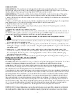
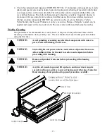
OPTION 1: The electrical cord is shipped from the factory protruding from the bottom rear corner of the
base and will fall through the required cut in counter. After the case has been installed and fastened onto
the counter, plug cord into a proper power source.
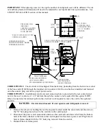
CORD OPTION 2: An additional electrical cord connection hole is provided in the rear control panel next
to the case’s controls. A 1-1/2”dia hole through the counter is not required for this option. NOTE: Only a
licensed electrician must perform the electrical work required to move the cord to this optional position.
DANGER:
Electric shock hazard. Do not operate unit with panels removed.
1.
Remove the (8) screws holding the rear frame panel located under the door track and also remove
the 7/8” hole plug located next to the controls in the control panel.
2. Disconnect the power cord connections and move the cord and cord strain relief from the bottom
hole in the frame channel to the hole in the control panel and reconnect power cord. Plug bottom
hole in frame channel with the 7/8” hole plug removed from the control.
3. Reinstall the rear frame panel.
Connect remote refrigeration lines
.
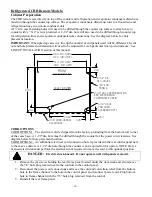
1. Remove the cover by removing the (4) screws on the bottom of case inside the cabinet
compartment.
2.
Connect remote refrigeration as described in the Remote Connection section in this manual. A 2-3/4
hole through the condensate evaporator compartment is provided.
3.
Make sure that the drain line has not been dislodged during shipment and that the drain trap is
located properly over the water reservoir of the condensate evaporator pan.
4.
Reinstall evaporator condensate cover.
Condensing Unit Air Flow.
The remote condensing unit must be installed to allow separation of coil intake air and coil discharge
air. The coil discharge air must not be allowed to recirculate back into the coil intake. Condensing unit
coil intake air temperature should be as cool as possible and should not exceed 80 Degrees F.


