FEC Remote Lighting Controller V4 HP0832
User Installation and Operation Manual
© Interleader Ltd 2020
57 of 64
26/08/2020
17.2 Example Switch
– Twilight Switch
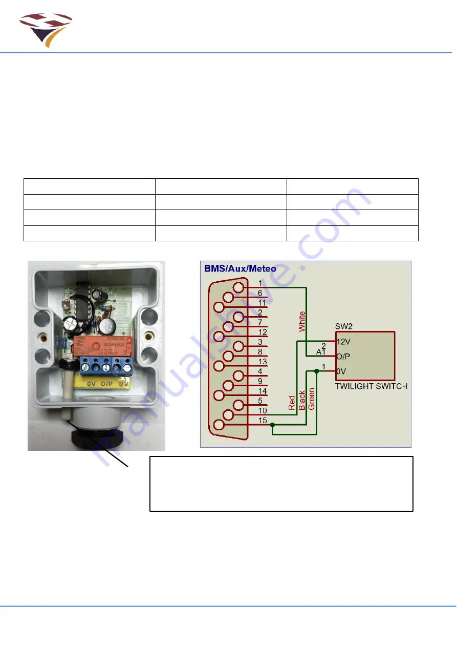
The following is an example of the wiring for a standard, low voltage light level switch. The
example shown (with cover removed) is a Danlers
‘Twilight’ switch which has been suitably
modified to work with the RLC.
This switch should be mounted externally, protected from the weather and not pointing at any light
source, particularly the lights it will control.
Connection to the RLC is via 4 core 0.35mm
2
(22 AWG) instrument cable (AlphaWire 1174L or
similar).
The wiring is connected as follows:
15
Way Male ‘D’ Connector
Cable Core
Twilight Switch
Pin 10
Red wire
12V
Pin 1
White wire
O/P (Output from switch)
Pin 15
Black and Green wires
0V
Once installed use the Aux input screens to confirm that the switch is closing.
Note that the switch has a time-delay of many seconds to avoid false triggers. Ensure you take
this into account when testing the switch.
Control for adjusting light level at which switch will come on.
Use a small screwdriver to make small adjustments, waiting
for 10 seconds each time to confirm the change.
Содержание HP0832
Страница 64: ...End of Document...


