background image

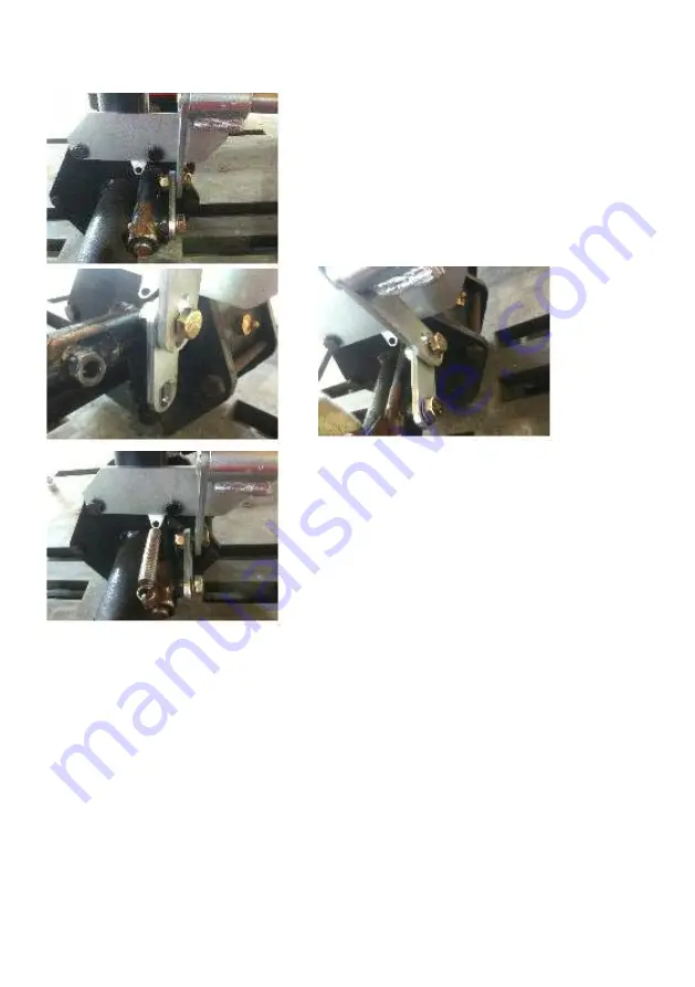
                                                                  J) 

Assemble  the  clutch  lever  set 

                                                                      with  gearbox  clutch

                                                                  K)                                                                    L)

                                                                  M) 

Assemble  the  spring

-  18  -

Содержание agromaster ITS-400P

Страница 1: ...FarmTech Machinery Pty Ltd 30 Moloney Drv Wodonga Vic 3690 Ph 02 60246800 Fax 02 60246844 www farmtech com au ...

Страница 2: ... 1 2 Technical data 1 3 Parts 2 4 How to Operate 3 4 5 Important safety information 4 6 Checkup 5 7 Storage 5 8 Parts sales Trouble shooting 6 9 Warranty complimentary check up Repair 6 11 Certificate of Quality Assurance 7 ...

Страница 3: ...5 16 5 16 5 16 POWER GROUND DRIVEN GROUND DRIVEN GROUND DRIVEN 1 Introduction 1 Power source is not necessary since it is operated by rotating the wheel 2 The spreading angle can be adjusted Three spreading patterns 4 Adjust the spreading amount by adjusting lever 5 Yellow hopper makes rust free and visible inside 6 It can spread by ATV UTV and compact tractor 7 Stainless Steel Prevention plate Va...

Страница 4: ...3 Parts Pull Type Spreader ITS 400P 700P 900P Hopper Frame Tires Tongue Shutter Spreading Direction Vanes Disc Gearbox Prevention Plate Mud Guard 2 ...

Страница 5: ... equipment to ATV or a tractor 3 If the horizontality is not maintained use the horizontality maintaining pole to do so 4 Close the outlet and pour fertilizer into the hopper Cable remote control 5 Turn the clutch lever left to transmit the power Turn the clutch lever right to cut off the power Please cut off the power on the move 3 ...

Страница 6: ...ver Cable remote control 7 Spread fertilizer by hauling through ATV or a compact tractor 9 Three spreading patterns A simple adjustment of shutter level allows direction of distribution towards the righthand side or towards the lefthand side 4 ...

Страница 7: ...n 1 Safety gear must be worn while operating the machine 2 If more than two people are operating the machine observe the others movement carefully 3 Make sure there is NO one or no obstacle within the operating area and its range 4 Do NOT overload or apply excessive force to the equipment 5 Perform pre operation procedures In particular check for loosen nuts and bolts connecting pins and Lubricant...

Страница 8: ...hen the equipment is to be stored for a long time apply lubricants to the area where it is likely to have corrosion 2 Firmly secure the fertilizer spreader on the flat surface to prevent any possible fall off 3 Keep it away from children to prevent any safety hazard 4 When the equipment is to be stored for a long time store it in indoor If it is to be stored outside place it on the flat surface an...

Страница 9: ...2 1887 6 16 12 0 20 4 81 3 185 6 331 7 468 5 608 6 779 4 983 9 Medium Grain Fertilizers 6 5 5 0 61 5 268 1 639 6 1152 5 1584 9 1833 9 2287 8 2848 7 10 8 0 25 109 260 468 5 644 2 910 5 1068 5 1370 7 13 12 0 13 3 57 9 138 248 8 342 1 409 5 493 8 616 5 Fine Grain Fertilizers 6 5 0 29 3 180 9 497 4 810 1242 9 1815 5 2130 7 2733 2 7 5 8 0 14 7 90 7 249 5 406 2 623 3 745 5 930 1158 11 12 0 6 6 40 8 112 ...

Страница 10: ...69 4 660 3 932 5 1211 4 1551 3 1958 4 15 12 0 21 8 86 8 198 354 450 649 5 831 7 1050 Medium Grain Fertilizers 6 5 0 66 5 289 9 691 6 1246 2 1713 7 1983 2473 8 3080 3 9 8 0 27 8 121 288 6 520 715 1 962 3 1129 4 1448 8 11 12 0 15 65 4 156 281 1 386 6 457 3 558 694 8 Fine Grain Fertilizers 5 5 5 0 31 9 197 2 542 3 883 1355 1979 2 2322 9 2979 8 7 8 0 15 5 95 9 263 7 429 3 658 8 827 5 1032 3 1285 4 10 ...

Страница 11: ...you purchased the equipment or our main office Trouble shootings 1 If any malfunction occurs please refer to Trouble Shooting section first 2 If Trouble Shooting does not solve the issue contact authorized dealer or manufacturer s Customer Service 10 Warranty complimentary check up Repair 1 The warranty is for one year from the date of delivering to the customer 2 Even after one year warranty peri...

Страница 12: ...AXLE 2 FRAME 1 HOPPER BRACE 2 HOPPER RING A Fix the frame on the proper bracket of gearbox and axle by 4 SCREWS M12x110 4 LOCK NUTS M12 8 WASHERS M12 B Fix the hopper brace on the proper bracket of the frame by 4 SCREWS M12x75 4 LOCK NUTS M12 8 WASHERS M12 10 ...

Страница 13: ...C Fix the hopper ring on the proper bracket of the frame and hopper brace by 8 SCREWS M10x40 8 LOCK NUTS M10 16 WASHERS M10 11 ...

Страница 14: ...1 DISC VANE DISC S UPPER BUSHING AND SPREADING SHAFT A Fix the spreading shaft into the disc upper busing by 1 SUS SCREW M8x45 and 1 SUS FLANGE NUT M8 B Tighten C C 12 ...

Страница 15: ...C Fix the disc vane disc s upper bushing spreading shaft on the proper rotary bushing of the gearbox and axle by 6 SUS SCREWS M8x25 4 SUS LOCK NUTS M8 13 ...

Страница 16: ...1 HOPPER 2 SHUTTER LOCK SET A B C D E F 14 ...

Страница 17: ...he hopper into the hopper ring by centering B Fix the hopper brace on the proper bracket of the hopper ring by 4 SUS SCREWS M10x40 4 SUS LOCK NUTS M10 8 SUS WASHERS M10 C Tighten D Tighten E Tighten F Tighten 15 ...

Страница 18: ...1 LOWER AGITATOR 2 CLUTCH LEVER SET A Insert the lower agitator and then fix the lower agitator on the shaft by 8 SUS SCREWS 8x45 and 1 SUS FLANGE NUTS M8 B Tighten C Assemble the clutch lever set 16 ...

Страница 19: ...D E 1 key 8x7x40 F G Fix the clutch lever on the proper bushing of the frame by 1 SCREWS M10x25 and 1 WASHER M10 H 1 SCREWS M8x15 I Tighten 17 ...

Страница 20: ...J Assemble the clutch lever set with gearbox clutch K L M Assemble the spring 18 ...

Страница 21: ...DJUSTING BAR SET A Fix the lever cable on the proper bracket of the frame by 2 SCREWS M6x20 and 2 LOCK NUTS M6 B Tighten C Fix the adjusting bar B on the proper bracket of the frame by 1 SCREWS M10x25 and 2 NUTS M10 19 ...

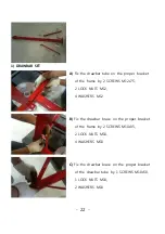
Страница 22: ...ghten E Fix the lever cable on the proper bushing of the lever cable by 1 SCREWS M8x25 and 1 LOCK NUTS M8 F Tighten G Fix the adjusting bar A on the proper hole of the shutter by 1 WASHER M10 and 1 RPIN 20 ...

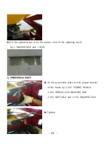
Страница 23: ...r hole of the adjusting bar B by 1 WASHER M10 and 1 RPIN 1 PREVENTION PLATE A Fix the prevention plate on the proper bracket of the frame by 2 SUS SCREWS M10x25 2 SUS SPRING LOCK WASHERS M10 2 SUS NUTS M10 and 4 SUS WASHERS M10 B Tighten 21 ...

Страница 24: ...by 2 SCREWS M12x75 2 LOCK NUTS M12 4 WASHERS M12 B Fix the drawbar brace on the proper bracket of the frame by 2 SCREWS M10x35 2 LOCK NUTS M10 4 WASHERS M10 C Fix the drawbar brace on the proper bracket of the drawbar tube by 1 SCREWS M10x50 1 LOCK NUTS M10 2 WASHERS M10 22 ...

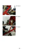
Страница 25: ...D Tighten E Tighten F Tighten 23 ...

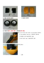
Страница 26: ...BRACE 2 MUD COVER 3 18x8 5 8 ITS 400P 700P 20x10 8 ITS 900 A Fix the mud cover brace on the proper bracket of the drawbar tube by 1 SCREWS M10x50 1 SPRING LOCK WASHERS M10 1 NUTS M10 and 2 WASHERS M10 B Tighten 24 ...

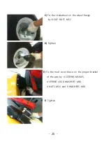
Страница 27: ...he tire wheel on the wheel flange by 8 CAP NUTS M12 D Tighten E Fix the mud cover brace on the proper bracket of the axle by 4 SCREWS M10x25 4 SPRING LOCK WASHERS M10 4 NUTS M10 and 8 WASHERS M10 F Tighten 25 ...

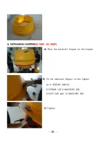
Страница 28: ...1 EXTENSION HOPPER KS 700P KS 900P A Place the extension hopper on the hopper B Fix the extension hopper on the hopper by 8 SCREWS M8x30 8 SPRING LOCK WASHERS M8 8 NUTS M8 and 16 WASHERS M8 C Tighten 26 ...

Страница 29: ......

Страница 30: ... be at its best condition and outstanding performance and safely maintained Thus we are pleased to offer you the assurance terms as below 1 SCOPE OF WARRANTY If the product you purchased was managed and used in accordance with instructions on regular check ups and maintenance schedule provided in the owner s operation manual AND the product is still within warranty period and used less than allowe...

Страница 31: ... office for inspections and repairs 3 RESPONSIBILITIES OF THE OWNER Since any unauthorized inspections or use of non genuine parts that are not prescribed in Owner s Operation Manual may decrease the performance of the parts or cause fatal damages to the product it is very critical to follow all the instructions prescribed in the Owner s Operation Manual and Certificate of Quality Assurance 4 EXCL...

Страница 32: ...ine parts 6 Any defect caused by negligence in storing and managing such as damages due to extreme weather conditions 7 Minor issues not related with the function smell vibrations shape sensitivity 8 Major discrepancies between the parts and its serial numbers recorded in our data base 9 Malfunction caused by natural calamities 5 PROCEDURE FOR WARRANTY REPAIR Warranty repair will be provided in ou...

Страница 33: ...g warranty time even after the transfer of ownership through sale or donation it is very important to acquire the Certificate of warranty when transfer of the product takes place We will honor all the terms prescribed above However if you are not satisfied with the service provided to you you may contact our customer service center directly and we will do our best to support you ...

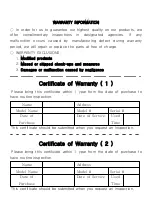
Страница 34: ...nty period we will repair or replace the parts at free of charge WARRANTY EXCLUSIONS 1 Modified products 2 Missed or skipped check ups and measures 3 Damages or malfunction caused by negligence Certificate of Warranty 1 Please bring this certificate within 1 year from the date of purchase to have routine inspection This certificate should be submitted when you request an inspection Certificate of ...

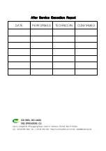
Страница 35: ...DATE PERFORMED TECHNICIAN CONFIRMED After Service Execution Report ...

Страница 36: ......

Страница 37: ...P O BOX 638 WODONGA VIC 3689 ...

Отзывы: