


Rev.23
114/311
5.8.
Configurable inputs
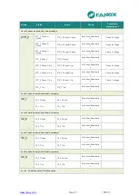
The SIL-B has eight digital inputs that can be configured by the user. The inputs can be configured
from the HMI or through the SICom program.
Firstly, we will define the concepts of physical input and logical input. Physical inputs are the
equipment’s real inputs. The SIL-B has eight physical inputs: Input 1, Input 2, Input 3,... up to
Input 8. These physical inputs can be associated with the logical inputs. The SIL-B has the
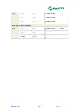
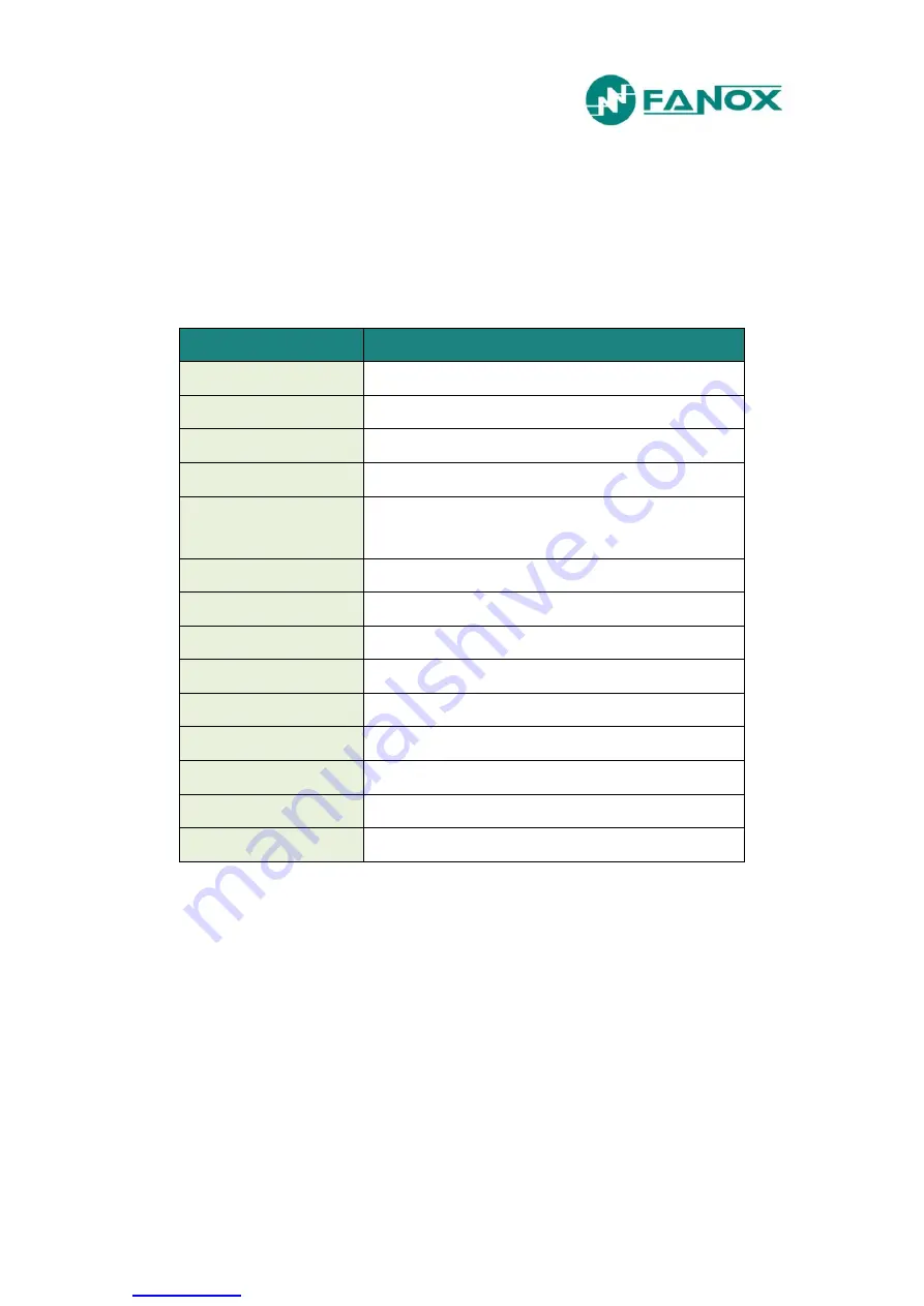
following logical inputs:
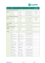
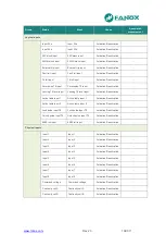
Logical inputs
Description
Input 52 a
Circuit breaker contact a
Input 52 b
Circuit breaker contact b
50P block input
Function 50P1 and 50P2 trip lock
50N/G block input
Function 50N/G1 and 50N/G2 trip lock
External trip input
External trip start. If a pulse of more than 20 ms is received (to avoid
false signals), a 200 ms pulse is generated to be used in the trip
output.
Fault init Input
Oscillography Start
79 init input
Start of 79 through external protection
Permission 79 input
Permission to close 79
Locking 79 level input
Lock of 79 through a level input
Input-1 Table Active
Active table assignment
Input-2 Table Active
Active table assignment
Locking 79 input pulse
Lock of 79 through a pulse input of an RTU
Unlock 79 pulse input
Unlock of 79 through a pulse input of a RTU
50BF init input
Start of circuit breaker fault through external protection
The inputs are configured by associating the logical inputs with the required physical input, or to
none if the logical input is not used. Therefore, a single physical input can be assigned to more
than one logical input.
Содержание SIL B
Страница 1: ...EN_FANOXTD_MANU_SIL_Feeder_SILB_R023 Docx USER S MANUAL SIL B Feeder Relay...
Страница 8: ...www fanox com Rev 23 8 311 2 DIMENSIONS AND CONNECTION DIAGRAMS 2 1 Equipment front view...
Страница 9: ...www fanox com Rev 23 9 311 2 2 Equipment dimensions...
Страница 10: ...www fanox com Rev 23 10 311...
Страница 11: ...www fanox com Rev 23 11 311 2 3 Cut out pattern CUT OUT PATTERN...
Страница 12: ...www fanox com Rev 23 12 311 2 4 Connection diagrams Analog connections...
Страница 13: ...www fanox com Rev 23 13 311...
Страница 14: ...www fanox com Rev 23 14 311 Digital connections Outputs and Trip circuit supervision...
Страница 15: ...www fanox com Rev 23 15 311 2 5 Terminals IEC 61850 or DNP3 0 protocols...
Страница 17: ...www fanox com Rev 23 17 311 IEC 60870 5 103 protocol...
Страница 25: ...www fanox com Rev 23 25 311 3 3 Functional diagram...
Страница 28: ...www fanox com Rev 23 28 311 3 5 1 SIL B 1 CHARGE CURVE 3 5 2 SIL B 5 CHARGE CURVE...
Страница 38: ...www fanox com Rev 23 38 311 4 6 4 Thermal protection curves This is the thermal curve for 3 minutes...
Страница 91: ...www fanox com Rev 23 91 311...
Страница 140: ...www fanox com Rev 23 140 311...
Страница 194: ...www fanox com Rev 23 194 311 Polarization V 35 0 V C Operating Angle 180 C Halfcone Angle 3 C...
Страница 307: ...www fanox com Rev 23 307 311 50BF init Fault init 79 Closure permission 52 closure permission...
Страница 308: ...www fanox com Rev 23 308 311 12 8 LED s configuration LEDs Blinking Latch Negate d LED On LED 1 LED 2 LED 3 LED 4 LED 5...
Страница 310: ...www fanox com Rev 23 310 311 NOTES...
Страница 311: ...www fanox com Rev 23 311 311...


