


Rev.17
26/119
This counter reading can be set to any value from within its range from the HMI or by communications.
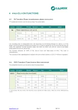
4.7.4. Excessive openings per time
As well as counting the number of times the circuit breaker opens, the SIA-F device sets up a time
window and the maximum number of openings allowed during this time. Both parameters can be
adjusted.
When this number is exceeded, the "Repeated Trips" state is activated and its corresponding event is
generated.
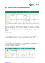
4.8.
49 Function. Thermal Image Protection
Thermal image is a measure of heating and cooling of an electric machine. Unlike overcurrent
protection, do not start counting the time when it detects a fault, but is continuously determining the
thermal state of the machine that monitors. The trip time depends on the thermal constants adjusted,
the current flowing and the prior thermal state of the machine.
The thermal image is calculated based on the following equation:
θ = 100 x (I/I
t
)
2
x (1
– e
-
t/ζ
) + θ’
0
x e
-
t/ζ
Where:
I, maximum R.M.S. current of three phases
I
t,
adjusted tap current
ζ, thermal constant
θ’
0
, initial thermal state
The trip time is given by the equation:
t =
ζ x ln x {[(I/I
t
)
2
–
(θ’
0
/ 100)] / [(I/I
t
)
2
- 1]}
The accuracy of the tripping time is ±5% or ± 2 s (the greatest of both values) the theoretical time.
The algorithm uses the maximum of the three phase currents. If the maximum is greater than 15% of
the adjusted tap, heating thermal constant is applied. If the maximum is less than 15% of the adjusted
tap cooling thermal constant is considered.
The overload function trips when the thermal image reaches the value of 100%. This value is reached
in time when the current flowing is equal to the function adjusted in thermal function.
It provides an adjustable level of thermal imaging to generate an alarm. If the trip occurs, the function
of overload is reset when the thermal image falls below the set alarm level.
As the current measurement algorithm used is R.M.S., in the thermal model is considered the heat
produced by the harmonics.
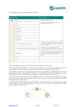
This protection function is adjusted by setting five different parameters
:
Function
Description
Minimum
Maximum
Pitch
Unit
Default
49
Thermal image protection function (*)
Permission
-
-
Yes/No
-
No
Tap
0,10
2,40
0,01
I nom
1,2
ζ heating
3
600
1
min
3
ζ cooling
1
6
1
ζ heating
1
Alarm
20
99
1
%
80
(*) Optional depending on model
Содержание SIA-F
Страница 7: ...www fanox com Rev 17 7 119 2 DIMENSIONS AND CONNECTION DIAGRAMS 2 1 Frontal view...
Страница 8: ...www fanox com Rev 17 8 119 2 2 Case dimensions The dimensions are in mm CUT OUT PATTERN...
Страница 9: ...www fanox com Rev 17 9 119 2 3 Connection diagram 3 Phase CT and neutral CT Connection...
Страница 10: ...www fanox com Rev 17 10 119 3 Phase CT and residual neutral Connection...
Страница 18: ...www fanox com Rev 17 18 119 3 5 2 Load curve for relay SIA F 1 3 5 3 Load curve of relay SIA F 5...
Страница 34: ...www fanox com Rev 17 34 119...
Страница 35: ...www fanox com Rev 17 35 119...
Страница 36: ...www fanox com Rev 17 36 119...
Страница 117: ...www fanox com Rev 17 117 119 9 6 Comments Person in charge of commissioning Date Maintenance performed on the by...
Страница 118: ...www fanox com Rev 17 118 119 NOTES...
Страница 119: ...www fanox com Rev 17 119 119...