


www.fanox.com
Installation_Guide_SIAB000B0010AA_Rev. 03 28 / 32
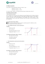
TEST 3
Settings:
-
Permission: YES.
-
Curve: IEC Inverse.
-
Dial: 0.5
-
TAP: 1xIs=16 A.
-
Theoretical tripping time = 5.01 seconds (Fault
current 32A)
o
admissible current measurement: 32+5%= 33.6 A.
Time: 4.68s -5% = 4.446s
o
admissible current measurement: 32-5%= 30.4 A
Time: 5.42s +5% = 5.691s.
The following information will be checked
:
-
Pick-up at 110% of the tap
-
Trip output is activated
-
Trip flag is activated
•
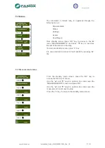
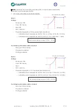
51N Inverse time neutral overcurrent protection:
TEST 1
Settings:
-
Permission: YES.
-
Curve: IEC Inverse.
-
Dial: 0.05
-
TAP: 1xIs.
-
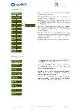
Theoretical tripping time= 1.56 seconds (Fault current 20A)
o
admissible current measurement: 20+5%= 21 A.
Time: 1.28s -5% = 1.216s
o
admissible current measurement: 20-5%= 19 A
Time: 2.03s +5% = 2.1315s.
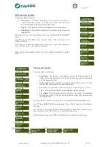
The following information will be checked
:
-
Pick-up at 110% of the tap
-
Trip output is activated
-
Trip flag is activated
Real admissible tripping time range: [4.446
s…5.691s]
Real admissible tripping time range: [1.216
s…2.1315s]