FANOX SIA-B Скачать руководство пользователя страница 14


www.fanox.com  

                Installation_Guide_SIAB000B0010AA_Rev. 03                                          14 / 32 
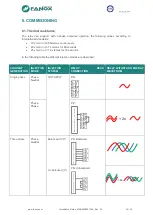


5.1. Test Winding 

Unlike the standard current transformers that provide a nominal secondary current of 1A or 5A, 
these specific current transformers have a very low current at their secondary.  

SIA-B  relay  has  been  designed  to  work  with  these  current  levels.  For  this  reason,  it  is  not 
possible to do the same tests that are performed with relays that use standard CTs. 

The  testing  consists  on  the  injection  of  1A  in  test  winding  terminals,  providing  a  simulated 
primary current value, that will have a different primary value depending on the selected CT. 


6. OPENING MECHANISM 


The trip is associated to a striker. The type of trip is a polarized trip. There are a lot of models of 
strikers  in  the  market,  with  different  trip  energies,  being  for  example  50  mJ  (0,05W·s)  and 
operation voltage of 6V, or 135 mJ (0,1W·s) and operation voltage of 24V. 

The opening mechanism is activated by means of a striker. The activation of the trip generates 
a pulse train. 

The 

Trip Voltage Level

 setting  allows  adjusting the  trip  voltage  level required  by  the selected 

striker. The default value is 17 Vdc, although there are several options: 


12 Vdc 


17 Vdc 


22 Vdc 


24 Vdc 

The  equipment  will  allow  the  trip  when  it  gets  the  selected  trip  voltage,  so  if  a  lower  level  that 
the required by the striker is adjusted, it may result on tripping without enough energy and not 
activating the striker.  

On the other hand, if a higher level that the required by the striker is selected, the activation of 
the  striker  is  guaranteed,  however,  the  fault  trip  time during  start-up  may  be  increased.  Fanox 
encourages  selecting  the  correct  value  of  this  critical  setting  and  offers  its  expertise  at  any 
doubt. 

Striker 

The striker is a bistable device with a simple action. The striker shaft is moved by a spring. The 
striker  is  activated  by  a  polarized  low-power  electrical  signal,  supplied  by  the  relay  if  a  fault 
occurs. Resetting the shaft to its position is done manually. Resetting the striker has to be done 
in  such  a  way  as  to  guarantee  that  the  opening  mechanism  is  closed.  This  is  normally  done 
manually. 


Due to the existing variety in the market, it is important to check the voltage and the necessary 
energy for its activation. 

Содержание SIA-B

Страница 1: ...INSTALLATION COMMISSIONING GUIDE SIA B Self Dual Power Overcurrent Protection Relay...

Страница 2: ...Flag 8 2 3 LED indicators 8 2 4 How to install SICOMM software 8 2 5 Setting up the session Password and access levels 9 3 FUNCTIONAL DIAGRAM 9 4 TECHNICAL SPECIFICATIONS 10 4 1 IEC60255 151 Curves 1...

Страница 3: ...rotocol is a certificate that relay has passed all factory testing process with correct results In case some fault is detected consider putting into quarantine period the relay and contact Fanox for f...

Страница 4: ...time NOTE Date and time must be correctly set the first time the relay is operative and energy must be kept at least 1 hour to maintain the RTC for 72 hours once the energy is lost Besides the possibi...

Страница 5: ...ns to increase or decrease the contrast 1 3 2 Test menu NOTE When performing test menu protection won t be available and it will be possible to open circuit breaker Only authorized personnel can do th...

Страница 6: ...us situation 2 Unscrew the 4 screws on the front of the relay to extract it from the RMU and access to the rear side of the relay 3 Unscrew the 2 screws to remove the cover from the battery compartmen...

Страница 7: ...the wiring of the switchgear and connect relay properly A1 Phase A current input for measurement and self power C1 Trip output A2 Phase A current output for measurement and self power C2 Trip output...

Страница 8: ...Magnetic Indicator trip There is a general trip without indicating the reason 2 3 LED indicators The SIA B front panel has two not configurable LEDs By default they show ready LED ON and alarm LED AL...

Страница 9: ...tatus and measurements Settings Events Permission to Change settings Download and Delete the Events buffer Permission to Execute Commands Permission to Change Configuration Permission to Change Protec...

Страница 10: ...tion level 100 Deactivation level 90 Instantaneous deactivation Timing accuracy 40 ms or 0 5 whichever is greater Function 50N Permission yes no Operating range 0 20 to 20 x Is step 0 01 x Is Operatin...

Страница 11: ...level 90 Instantaneous deactivation Timing accuracy 5 or 30 ms whichever is greater when the protection works with inverse time and 40 ms or 0 5 whichever is greater when it works with definite time F...

Страница 12: ...me Inverse 120 1 1 0 0 Ext Inverse 80 2 1 0 0 Very Inverse 13 5 1 1 0 0 Inverse 0 14 0 02 1 0 0 The curve can move from its axis using the D time selection device which the user can adjust Iadjusted i...

Страница 13: ...the user can adjust Iadjusted is the initial operating current set by the user 5 SPECIFIC CURRENT TRANSFORMERS SIA B relay requires specific CTs to achieve not only the line current measurement but al...

Страница 14: ...e Level setting allows adjusting the trip voltage level required by the selected striker The default value is 17 Vdc although there are several options 12 Vdc 17 Vdc 22 Vdc 24 Vdc The equipment will a...

Страница 15: ...ated or deactivated by pressing OK on it if the item is deactivated it is activated by pressing OK if the item is activated it is deactivated by pressing OK Press the C key to exit the test menu Once...

Страница 16: ...and assign a value to this digit using the and keys Once the date time has been entered press OK to change the equipment date Press the C key to return to the standby mode screen Contrast Hold key fr...

Страница 17: ...MEASUREMENTS and press key to overview the rest of the menus in the relay To return to standby screen press C key It is also possible to access to Fault reports by pressing key From the standby mode...

Страница 18: ...erneath the setting name is its value States menu indicates the stuses of the relay activated or deactivated at real time From the standby mode screen press the OK key to access the first line of menu...

Страница 19: ...function The parameters to adjust are Permission The function is available to work only if the permission is YES While this permission is NO the function will never be activated and the relay will not...

Страница 20: ...eral settings depends on which specific CT will be used in the application For example if a CT016 is used the Nominal Current would be the nominal current of the installation NOTE the installation nom...

Страница 21: ...ey to overview the options and press OK when Nominal current option appears After inserting the password 5555 it will be possible to select the desired value Pressing OK key from the standby screen it...

Страница 22: ...ry to insert the password 5555 from the events menu After the erasing of the events it will be appear there is 1 event corresponding to Events erased NOTE When the events are deleted the fault reports...

Страница 23: ...2 85xIsmax continuously 20 x Ismin or 5 7 x Ismax for 60 seconds 25 x Ismin or 7 14 x Ismax for 10 seconds In the following table the different injection modes are described CURRENT GENERATION INJECT...

Страница 24: ...protection functions settings Connect it for setting and disconnect it for testing purpose Adjust manually current generation value without injecting current to relay for not stressing it during adju...

Страница 25: ...phase minimum self powering checking Adjust the Sverker current generator with HOLD 0 4xIsmin and suddenly inject it to the relay as it would happened in real situation when circuit breaker is close...

Страница 26: ...etwork line From this value increase the current to achieve the function pick up and the function trip 8 4 1 Protection functions testing NOTE The followig testing processes will be done with the spec...

Страница 27: ...rement 24 5 22 8 A Time 0 98s 5 1 029s The following information will be checked Pick up at 110 of the tap Trip output is activated Trip flag is activated TEST 2 Settings Permission YES Curve IEC Inve...

Страница 28: ...of the tap Trip output is activated Trip flag is activated 51N Inverse time neutral overcurrent protection TEST 1 Settings Permission YES Curve IEC Inverse Dial 0 05 TAP 1xIs Theoretical tripping tim...

Страница 29: ...al tripping time 15 55seconds Fault current 28A o admissible current measurement 18 5 29 4 A Time 14 29s 5 13 575s o admissible current measurement 18 5 26 6 A Time 17 13s 5 17 98s The following infor...

Страница 30: ...ersion Wiring checking OK NOK USB communication port OK NOK Signalling and Keypad Led 1 OK Led 2 OK Trip OK Trip Output OK Keypad OK Self power 3P SIAC 0 4Is Phase A OK Phase B OK Phase C OK Commissio...

Страница 31: ...www fanox com Installation_Guide_SIAB000B0010AA_Rev 02 31 32 NOTES...

Страница 32: ...www fanox com Installation_Guide_SIAB000B0010AA_Rev 03 32 32...

Отзывы: