background image

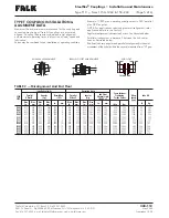
TYPE T COUPLING INSTALLATION &

ALIGNMENT DATA

Maximum life and minimum maintenance for the coupling and

connected machinery will result if couplings are accurately

aligned. Coupling life expectancy between initial alignment

and maximum operating limits is a function of load, speed and

lubrication.

Values may be combined for an installation or operating condition.

Example: 1180T max. operating misalignment is .030" parallel

plus .089" angular.
NOTE: For applications requiring greater misalignment, refer

application details to the Factory.
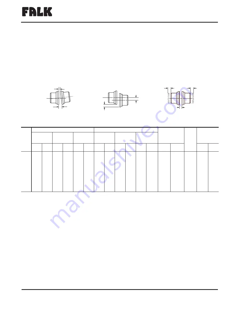
Angular misalignment is dimension X minus Y as illustrated below.
Parallel misalignment is distance P between the hub center

lines as illustrated below.
End float (with zero angular and parallel misalignment) is the axial

movement of the hubs(s) within the cover(s) measured from “O” gap.

®

The Falk Corporation, P.O. Box 492, Zip 53201-0492

428-112

3001 W. Canal St., Zip 53208-4200, Milwaukee, WI USA Telephone: 414-342-3131

May 2000

Fax: 414-937-4359 e-mail: [email protected] web: www.falkcorp.com

Supersedes 12-98

Steelflex

®

Couplings

Installation and Maintenance

Type T10

Sizes 1150–1260 & 150–260

(Page 5 of 6)

TABLE 2 — Misalignment And End Float

CPLG

SIZE

Installation Limits

Operating Limits

Cover Fastener

Tightening

Torque Values

Allow

Speed

(rpm)

Lube Wt

Parallel

Offset-P

Angular

(x-y)

Normal Gap

±

10%

Parallel

Offset-P

Angular

(x-y)

End Float

Physical Limit

(Min) 2 x F

Max

In.

Max

mm

Max

In.

Max

mm

In.

mm

Max

In.

Max

mm

Max

In.

Max

mm

In.

mm

lb-in

Nm

lb

kg

1150T

.012

.305

.016

.406

.250

6

.024

.610

.062

1.57

.620

15.7

650

73.4

1500

4.3

1.95

1160T

.012

.305

.018

.457

.250

6

.024

.610

.070

1.79

.640

16.3

650

73.4

1350

6.2

2.81

1170T

.012

.305

.020

.508

.250

6

.024

.610

.079

2.01

.617

15.7

1300

146.9

1225

7.7

3.49

1180T

.015

.381

.022

.559

.250

6

.030

.762

.089

2.26

.717

18.2

1300

146.9

1100

8.3

3.76

1190T

.015

.381

.024

.610

.250

6

.030

.762

.097

2.46

.620

15.7

1300

146.9

1050

9.7

4.40

1200T

.015

.381

.027

.686

.250

6

.030

.762

.107

2.72

.620

15.7

2300

259.9

900

12.4

5.62

1210T

.018

.457

.029

.737

.500

13

.036

.914

.118

3.00

1.02

25.9

2300

259.9

820

23.2

10.5

1220T

.018

.457

.032

.813

.500

13

.036

.914

.129

3.28

1.15

29.2

3580

404.5

730

35.4

16.1

1230T

.019

.483

.035

.889

.500

13

.038

.965

.142

3.61

1.12

28.4

3580

404.5

680

53.0

24.0

1240T

.019

.483

.038

.965

.500

13

.038

.965

.154

3.91

1.12

28.4

5350

604.5

630

74.5

33.8

1250T

.020

.508

.042

1.07

.500

13

.040

1.02

.169

4.29

1.12

28.4

5350

604.5

580

110.5

50.1

1260T

.020

.508

.046

1.17

.500

13

.040

1.02

.183

4.64

1.01

25.7

5350

604.5

540

148.1

67.2

GAP

Y

X

F

F

ANGULAR MISALIGNMENT

P

P

PARALLEL OFFSET MISALIGNMENT

END FLOAT

Содержание Steelflex T10

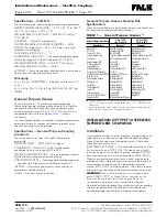
Страница 1: ... specifications for general purpose and long term greases Because of its superior lubricating characteristics and low centrifuge properties Falk Long Term Grease LTG is highly recommended The use of general purpose grease requires re lubrication of the coupling at least annually Long Term Grease LTG The high centrifugal forces encountered in couplings separate the base oil and thickener of general...

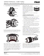
Страница 2: ...C using an oven torch induction heater or an oil bath To prevent damage DO NOT heat hubs beyond a maximum temperature of 400 F 205 C When an oxy acetylene or blow torch is used use an excess acetylene mixture Mark hubs near the center of their length in several places on hub body with a temperature sensitive crayon 275 F 135 C melt temperature Direct flame towards hub bore using constant motion to...

Страница 3: ...ss to the gap specified in Table 2 Page 5 Insert bar as shown above to same depth at 90 intervals and measure clearance between bar and hub face with feelers The difference in minimum and maximum measurements must not exceed the ANGULAR INSTALLATION limits specified in Table 2 3 Offset Alignment Align so that a straight edge rests squarely or within the limits specified in Table 2 on both hubs as ...

Страница 4: ... tightening torques of all fasteners 3 Inspect seal ring and gasket to determine if replacement is required If leaking grease replace 4 When connected equipment is serviced disassemble the coupling and inspect for wear Replace worn parts Clean grease from coupling and repack with new grease Install coupling using new gasket as instructed in this manual Periodic Lubrication The required frequency o...

Страница 5: ...nd Float CPLG SIZE Installation Limits Operating Limits Cover Fastener Tightening Torque Values Allow Speed rpm Lube Wt Parallel Offset P Angular x y Normal Gap 10 Parallel Offset P Angular x y End Float Physical Limit Min 2 x F Max In Max mm Max In Max mm In mm Max In Max mm Max In Max mm In mm lb in Nm lb kg 1150T 012 305 016 406 250 6 024 610 062 1 57 620 15 7 650 73 4 1500 4 3 1 95 1160T 012 3...

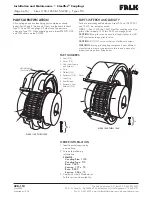
Страница 6: ...may cause premature failure and personal or property damage from flying debris The Falk Corporation P O Box 492 Zip 53201 0492 428 112 3001 W Canal St Zip 53208 4200 Milwaukee WI USA Telephone 414 342 3131 May 2000 Fax 414 937 4359 e mail falkinfo falkcorp com web www falkcorp com Supersedes 12 98 Installation and Maintenance Steelflex Couplings Page 6 of 6 Sizes 1150 1260 150 260 Types T10 PART N...

Отзывы: