I65/I56I HARDWARE DESCRIPTION VERSION
1.00
5.5 Automatic GPRS Multislot Class change
Temperature control is also effective for operation in GPRS Multislot class 10.
If the board temperature increases to the limit specified for restricted operation
(
see
for temperature limits known as restricted operating
) while data are
transmitted over GPRS, the module automatically reverts from GPRS Multislot
class 10 (3 RX x 2 TX) to class 8 (4 RX x 1 TX). This reduces the power
consumption and, consequently, causes the temperature of board to decrease.
Once the temperature drops to a value of 5 degrees below the limit of restricted
operation, I56/I56i returns to the higher Multislot class. If the temperature stays
at the critical level or even continues to rise, I56/I56i will not switch back to
the higher class. After a transition from Multislot class 10 to Multislot class 8 a
possible switchback to Multislot class 10 is blocked for one minute. Please
note that there is not one single cause of switching over to a lower GPRS
Multislot class. Rather it is the result of an interaction of several factors, such
as the board temperature that depends largely on the ambient temperature, the
operating mode and the transmit power. Furthermore, take into account that
there is a delay until the network proceeds to a lower or, accordingly, higher
Multislot class. The delay time is network dependent. In extreme cases, if it
takes too much time for the network and the temperature cannot drop due to
this delay, the module may even switch off as described in chapter
GPRS connection see related document [
5
].
5.6 GSM charging control
The GSM/GPRS part of the I56/I56i module integrates a charging management
for Li-Ion batteries. You can skip this chapter if charging is not your concern,
or if you are not using the implemented charging algorithm.
To benefit from the implemented charging management you are required to
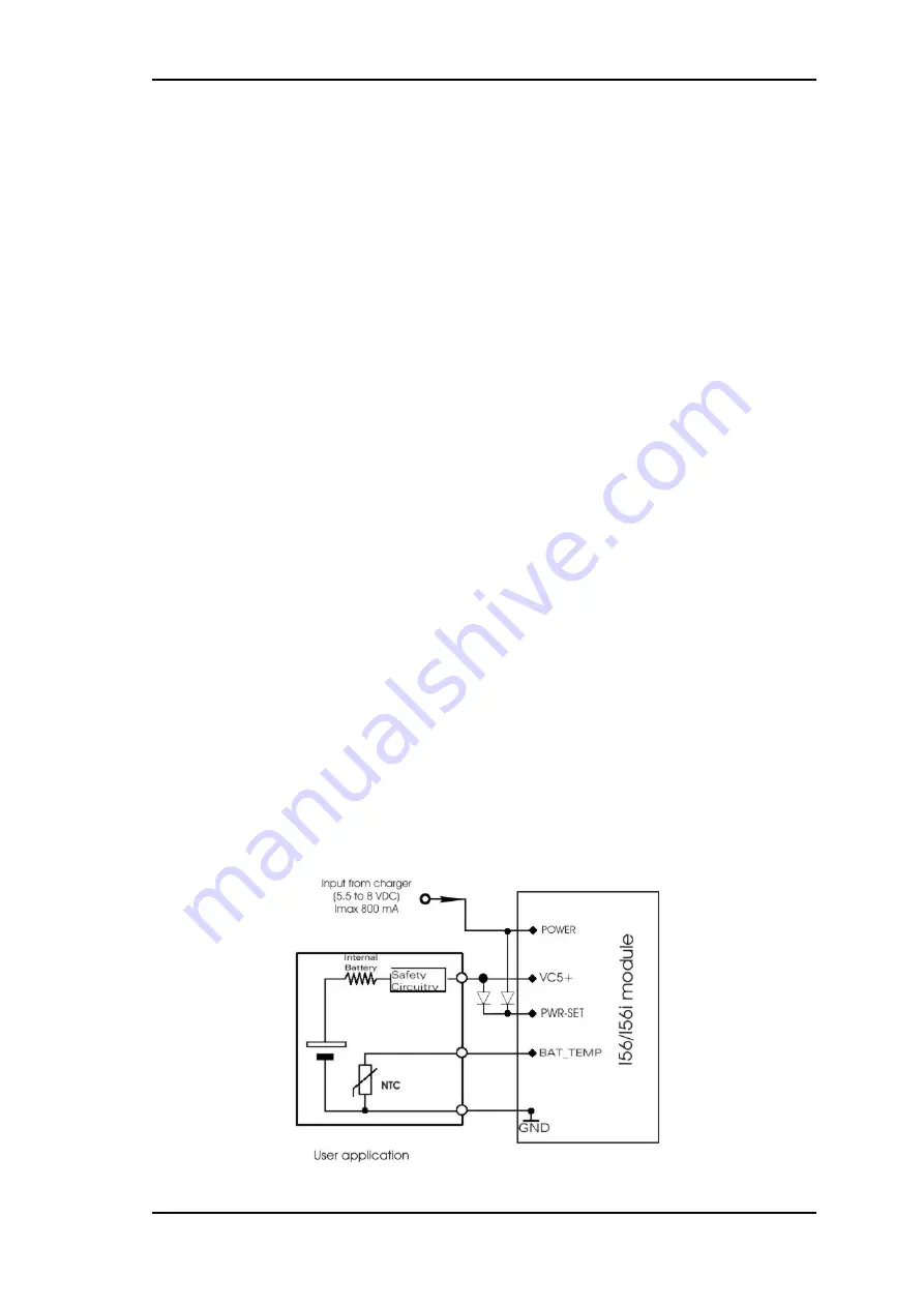
build a charging circuit within your application. In this case, I56/I56i needs to
be powered from a Li-Ion battery pack, e.g. as specified in chapter
The module only delivers, via its POWER line, the control signal needed to
start and stop the charging process. The charging circuit should include a
transistor and should be designed as illustrated in figure 6. A list of parts
recommended for the external circuit is given in table 12 below.
Figure 6:
Schematic of charging/discharging process.
This confidential document is the property of FALCOM GmbH and may not be copied or circulated without permission.
Page 34


