background image

43 


 16 

Maintenance of the hydraulic system 

Cleaning and replacing oil


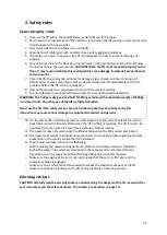
Three months after commissioning the lift, drain all oil out of the hydraulic sytem and fill the system 
with new oil. Afterwards this has to be done every six months, clean the hydraulic sytem and replace 
the oil. 

Replacing gaskets


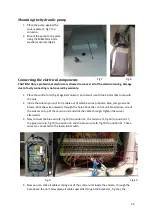
In case of a hydraulic leakage, subject the machine to a thorough inspection. If the leakage is caused 
by one or more worn gaskets you need to replace them immediately. 

Inspection 

CAUTION! The 2-post lift has to meet the following demands/standards

-


When commissioning, check if the manual is complete with EG-declaration of 
conformity, standard maintenance protocol and inspection certificate. 

-


Every 12 months the lift has to be inspected according to national norms by a specialized 
company and/or person. 

-


Valkenpower BV remains adhered for carrying out any inspections prescribed by law. 

-


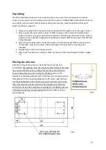
A thorough inspection for deformation by shockloads, corrosion, cracks and deformation 
has to be carried out every month when the lift is intensively used.   

Maintenance 

CAUTION! Checks and maintenance operations may only be performed by specialized mechanics. 

-


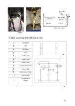
Check if the lift functions properly previous to each use. 

-


In case of uncertainties or deformation, the 2-post lift has to be taken out of use 
immediately. 

-


Broken parts may only be replaced by original Falcvo-parts, this may only be done by 
specialized mechanics. Failure to heed these instructions may invalidate the warranty. 

 10 

Содержание VL35F230

Страница 1: ...2 Koloms hefbrug 2 Post lift 2 S ulen Hebeb hne VL35F230 VL35F400 Montage en gebruiksinstructies Installation and operating instructions Montage und Bedienungsanleitung...

Страница 2: ...taalkabels 11 Het plaatsen van de hydraulische pomp 12 Het aansluiten van de elektrische voeding 12 Het monteren van de bodemplaat 15 Het aansluiten van de hydrauliekleidingen 15 Schematische weergave...

Страница 3: ...ties 26 9 Probleem oplossing 26 10 Garantie 27 Waarschuwingsstickers Warningstickers Warnaufkleber 70 Onderdelenlijst en tekening Partslist and drawing Teileliste und Zeichnung 71 Losse onderdelen Sep...

Страница 4: ...ing the steel wires 32 Mounting the hydraulic pump 33 Connecting the electrical components 33 Mounting the bottomplate 36 Connecting the hydraulic lines 36 Schematic drawing of the hydraulic system 37...

Страница 5: ...ubleshooting 47 10 Warranty 48 Waarschuwingsstickers Warningstickers Warnaufkleber 70 Onderdelenlijst en tekening Partslist and drawing Teileliste und Zeichnung 71 Losse onderdelen Separate parts Sepa...

Страница 6: ...Stahlkabeln 53 Montage der Hydraulikpumpe 54 Anschlie en des Netzteils 54 Montage der Boden Grundplatte 57 Anschluss der hydraulischen Leitungen 58 Schaltplan Bildsynthese Hydraulik System 58 Montage...

Страница 7: ...Technische Daten 68 9 Problem L sung 68 10 Garantie 69 Waarschuwingsstickers Warningstickers Warnaufkleber 70 Onderdelenlijst en tekening Partslist and drawing Teileliste und Zeichnung 71 Losse onder...

Страница 8: ...n het oog van de kwaliteit constant verbeteringen aan de apparatuur worden doorgevoerd behoud Valkenpower b v houder Falco zich het recht voor om specificaties van de in de handleiding beschreven appa...

Страница 9: ...gen tot 3500kg in een gesloten ruimte ieder ander gebruik is verboden Maak nooit gebruik van de brug wanneer veiligheidsvoorzieningen niet werken Het negeren van deze instructie kan ernstige schade ve...

Страница 10: ...sluitsnoer een kabel met een minimale aderdikte van 2 5mm 4 De betonvloer waarop de brug wordt geplaatst dient te voldoen aan onderstaande eisen De fundering van de lift moet voldoen aan de volgende e...

Страница 11: ...ig neer op de plek waar deze straks moet komen te staan 4 Herhaal de stappen 2 en 3 voor de onderste kolom 5 Kijk nu na of alle onderdelen compleet zijn deze zijn in de tabel Losse onderdelen op pagin...

Страница 12: ...lkabels geleverd deze dienen gemonteerd te worden 2 Til beide heflichamen in de laagste stand van de arretering 3 Haal de staalkabels uit de kolom en draai de moeren aan de kant waar de staalkabel vas...

Страница 13: ...bij de controle unit zitten 2 In de kolom vindt u een kabel waar 4 draden uitkomen blauw rood groen en bruin Steek deze kabel naar buiten door het gat boven de unit Draai nu de n van de wartels boveno...

Страница 14: ...en de ander voor de magneetklep van de hydraulische pomp De kabel die naar de limietschakelaar gaat is in de controle unit aangesloten op positie 5 en 102 de kabel van de magneetklep van de pomp is aa...

Страница 15: ...e en blauwe draad is aangesloten op posities 7 en 17 in de controle unit zie stap 4 13 Draai de moer waarmee de magneetklep vastzit aan de pomp los en verwijder de magneetklep van de pomp Draai nu bou...

Страница 16: ...kige sleuf fig 15c en plaats de kabels terug in de stekkers let hierbij op dat wanneer u de stekkers koppelt blauw op blauw aansluit en rood op rood 21 Koppel de stekkers nu aan elkaar Het monteren va...

Страница 17: ...systeem Nr Onderdeel 1 Filter 2 Tandwielpomp 3 Motor 4 Overstortklep 5 Terugslagklep 6 Magneet ventiel 7 Vloeiende regelklep 8 Drukmeter 9 Explosiebestendig ventiel 10 Hoofdcilinder 11 Secundaire cili...

Страница 18: ...ing tang plaats de rubberen pad Plaats de veerring terug wanneer de brug in geheven positie staat 6 Herhaal stappen 1 t m 5 voor de andere armen Het monteren van de flexibele afdekking voor de kolomme...

Страница 19: ...r geen lekkages zijn in het hydraulisch systeem 5 Controleer of de elektrische voeding voldoet aan de eisen van de brug en of deze goed geaard is Onbelast testen 1 Controleer of de draairichting van d...

Страница 20: ...de auto 100 150mm van de grond geheven is laat de knop los en stop het heffen Beweeg de auto zodat u er zeker van bent dat hij stevig en stabiel op de rubberen steunen rust Druk dan weer op de Hef kno...

Страница 21: ...ooppunt 6 Veiligheidsvoorziening Automatisch arreteringsmechanisme Iedere kolom is voorzien van twee magnetische arreteringen bestaande uit een Magneetspoel 1 Metalen as 2 Kolom 3 Arreteerpal 4 Stelmo...

Страница 22: ...rmen van de brug Wanneer de brug het laatste stukje zakt klinkt er een luide pieptoon om mensen te waarschuwen dat de brug nu zakt tot het laagste punt 7 Onderhoud Schoonhouden van de brug De brug die...

Страница 23: ...dsschema en inspectie certificaat De brug dient iedere 12 maanden gekeurd te worden volgens de nationale normen door een erkend bedrijf en of een gespecialiseerd persoon Valkenpower bv houdt zich aanb...

Страница 24: ...Falco onderdelen Controleer de ankerbouten op scheurtjes slijtage en tekenen van vervorming Vervang de ankerbout indien nodig zorg ervoor dat het gat in goede staat is gebruik minimaal M18 x 160mm bou...

Страница 25: ...leen originele Falco onderdelen Controleer of de olie niet vervuild of verouderd is Olie aflaten en vervangen door Falco CH46V Hydraulische olie Controleer of alle pakkingen nog goed zijn Kapotte vers...

Страница 26: ...t correcte serienummer Controleer of de sticker met het maximale hefvermogen aanwezig en goed leesbaar is Plaats een nieuwe sticker met de correcte indicatie voor het maximale hefvermogen 3500kg Contr...

Страница 27: ...gen Brug zakt automatisch tijdens het heffen Cilinder zuiger versleten Cilinder zuiger vervangen Lekkende olieleiding Leiding pakking vervangen of koppelingen goed aandraaien Pakkingen van de hydrauli...

Страница 28: ...garantie is niet van toepassing bij onoordeelkundig gebruik 7 Eventuele verzendkosten vallen niet onder de garantie bepaling 8 Reparaties dienen uitsluitend door Uw leverancier te geschieden Elk door...

Страница 29: ...tion of conformity These must be stored and kept up to date properly Because of quality reasons constant improvements are going to be made on the equipment Valkenpower bv holder Falco reserves the rig...

Страница 30: ...ift is strictly forbidden Never use the lift if the safety devices are not functioning like they should Ignoring this instruction may cause serious damage to equipment materials and persons 10 For the...

Страница 31: ...ion area is 2 5 square millimeters 4 The concrete floor on which the lift is being installed should meet the following standards The foundation of the lift should meet the following standards The conc...

Страница 32: ...ft the column out of the brackets Now put the column down carefully on the spot where it is going to be installed 4 Repeat step 2 and 3 for the lower column 5 Now check if all parts are complete these...

Страница 33: ...steel wires 1 The lift comes with two steel wires which are to be mounted into the columns 2 Lift both sliding tables in the first locking position 3 Now pull the steel wires out of the columns and l...

Страница 34: ...you will find a cable out of which 4 wires protrude blue red green and brown Stick the wire outwards through the hole above the control unit Now loosen one of the swivels on top of the control unit an...

Страница 35: ...les is to be connected to the upper limit switch the other is to be connected to the magnet valve of the hydraulic pump The cable that is to be connected to the upper limit switch is connected on posi...

Страница 36: ...1 fig 14b and remove the blue wires loosen the swivel and remove the cable with the two blue wires 15 Place the swivel and the cover over the signal cable with red and blue wire and connect the wires...

Страница 37: ...entire length of the plate fig 16 2 Now turn the bottom plate around and place it over the steel wires onto the columns 3 Mount the bottom plate to the columns using the 4 M12 bolts spring washers an...

Страница 38: ...ydraulic system Nr Onderdeel 1 Filter 2 Gearpump 3 Motor 4 Overflow valve 5 One way valve 6 Solenoid valve 7 Flowing control valve 8 Pressure gage 9 Explosion proof valve 10 Main cylinder 11 Supplemen...

Страница 39: ...Place back the circlip when the lift is in raised position DO NOT FORGET 6 Repeat steps 1 to 5 for the other arms Mounting the flexible column covers 1 Loosen the nuts and washers on the upper end of...

Страница 40: ...sealed 4 Check the hydraulic system for leakages 5 Check if the power source is adequate and that the ground wire is reliable Testing without load 1 The generator should turn in a direction consistent...

Страница 41: ...round release the button to stop lifting Move the car to make sure it sits firmly and stable on the rubber pads Now press the LIFT button again to lift the vehicle to the desired height Stopping Relea...

Страница 42: ...res Automatic safety locks Every column is provided with two safety locks consisting of a Magnet coil 1 Metal axle 2 Column 3 Lock plate 4 Adjusting nut 5 and Lifting body 6 refer to figure 21 How the...

Страница 43: ...feet stuck under the vehicle or arms of the lift During this last phase of lowering a loud beep tone will sound to alert people that the lift is lowering to its lowest position 7 Maintenance Cleaning...

Страница 44: ...tandard maintenance protocol and inspection certificate Every 12 months the lift has to be inspected according to national norms by a specialized company and or person Valkenpower BV remains adhered f...

Страница 45: ...eplace the anchor bolt if necessary make sure the hole is in good condition use at least M18 x 160mm bolts and preferably chemical anchoring Check the rubber pads for signs of wear and tear cracks and...

Страница 46: ...eck repair the motor Check if the motor and oil tank are still properly mounted to the column Tighten the bolt nuts and replace if necessary Electrical Check the conditions of all wiring and connectio...

Страница 47: ...lifting and lowering must be recognizable at all times Replace the stickers for indication of the control buttons by original Falco stickers Check the cleanliness of the work area under and around th...

Страница 48: ...ost effectiveness Fix the pistons Pipes are leaking oil Change the seals and tighten the nuts on the connection Seals on the hydraulic cylinders have lost effectiveness Change the seals The hydraulic...

Страница 49: ...not apply in case of injudicious use 7 Possible shipping costs are not covered by the warranty 8 Repairs should exclusively be carried out by your supplier Repair s carried out by others will result i...

Страница 50: ...befolgen Bewahren Sie diese Bedienungsanleitung immer in der N he der Maschine an einem leicht zug nglichen und trockenen Platz Behandeln Sie diese Bedienungsanleitung mit Vorsicht damit dieses nicht...

Страница 51: ...ll und schwerwiegende Sch den an Eigentum und Material f hren 10 Um die Sicherheit des Betreibers und Umstehende zu gew hrleisten bitten wir Sie bei nderungen in der Position der Hubbr cke eine Sicher...

Страница 52: ...Z Motorschutzschalter integriert ist Verwenden Sie ein Kabel mit minimaler Venen Dicke 2 5 mm 4 Der Beton Boden das Fundament auf dem der die Br cke platziert wird muss den folgenden Anforderungen ent...

Страница 53: ...ke aufgebaut wird 3 Wiederholen Sie die beiden vorweg beschriebenen Schritte f r den unteren Teil der S ule 4 Kontrollieren Sie ob die restlichen Teile wie in der Tabelle auf Seite 73 benannt vollst n...

Страница 54: ...ahlkabeln 1 Mitgeliefert zur Montage werden 2 Stahlkabel 2 Heben Sie die beiden Hubk rper in den untersten stand der Sicherung 3 Entfernen Sie die Stahlkabel aus der S ule Ziehen Sie die Muttern an de...

Страница 55: ...integrierten Kabeln in den Farben Blau Rot Gr n und Braun F hren Sie dieses Kabel raus durch das Loch an der oberen Seite der Einheit Lockern Sie die Kabelverschraubung und Ziehen Sie folgend das Kabe...

Страница 56: ...Kabel des Magnetventils der Pump ist mit den Positionen 7 und 17 verbunden 7 berzeugen Sie sich bevor Sie die Anschl sse mit einander verbinden das diese die korrekten Verbindungen darstellen 8 Anschl...

Страница 57: ...m Roten und Blauen Draht Verbinden sie diese beiden Kabel mit Hilfe der Klemmen Schrauben mit dem Magnetventil wie dargestellt in Abb 14c 16 Decken Sie das Magnetventil wieder mit der kappe ab und sic...

Страница 58: ...Stecker ein und stellen Sie dabei sicher das blau mit blau und rot mit rot einf gt 21 Verbinden Sie die Stecker Montage der Boden Grundplatte 1 Klicken Sie die lange Hydraulische Leitung 35 Seite 71...

Страница 59: ...eiden Seiten mit dem Zylinder Abb 17b 6 In Abb 17 c und 17 d finden Sie das Diagramm des Hydrauliksystems Schaltplan Bildsynthese Hydraulik System Nr Teil 1 Filter 2 Zahnradpumpe 3 Motor 4 Sicherheit...

Страница 60: ...ein Platzieren Sie den Federring wieder zur ck wenn sich die Br cke wieder in gehobenen Stand befindet 6 Wiederholen Sie die Schritte 1 bis 5 zur Montage der anderen Armen Montage zu der flexiblen Ab...

Страница 61: ...as die Stromversorgung den Anspr chen der Hubbr cke entspricht und ob diese ordnungsgem geerdet ist Test ohne Belastung durchf hren 1 berpr fen Sie ob die Drehrichtung des Motors der Drehrichtung ents...

Страница 62: ...Vergewissern Sie sich das die Stromversorgung eingeschaltet ist Aktivieren Sie die Hauptschalter der Stromversorgung 1 Abb 20 durch diesen von der Position 0 in Position 1 zu schalten Folgend leuchtet...

Страница 63: ...fenthalt innerhalb der Sicherheitszone Sperren Sie die Br cke sobald sich das Fahrzeug auf der gew nschten H he befindet Arbeiten an dem Fahrzeug sind erst dann erlaubt wenn sichergestellt ist das die...

Страница 64: ...er dass die Stellmutter nach dieser Handlung wieder gesichert wird Wenn der sanktionierte Sperrk rper nicht ausreichend zur ck zieht bleibt dieser in dem Sperrstand Dem zu folge ist es unm glich die B...

Страница 65: ...len Sie irgendwo an der Hubbr cke auslaufendes l fest bitten wir Sie an der Maschine eine gr ndlichen Inspektion durch zu f hren Ist der Auslauf zu Folge von Verschlei einer oder mehreren Dichtungen b...

Страница 66: ...berpr fen Sie die Ankerbolzen auf Risse Verschlei und Zeichen von Verzerrungen Fremdform Bei Bedarf ersetzen Sie die Ankerbolzen Stellen Sie sicher das das vorgebohrte Loch sich in einem einwandfreie...

Страница 67: ...ginalersatzteilen Vergewissern Sie sich dass das l nicht verunreinigt oder veraltert ist F hren Sie einen lwechsel durch Stellen Sie sicher dass alle Dichtungen noch einwandfrei intakt sind Defekt abg...

Страница 68: ...r dass der Aufkleber mit der maximalen Traglast vorhanden und deutlich lesbar ist Ersetzen Sie den Kleber mit einem welcher die maximale Traglast 3500Kg andeutet berpr fen Sie ob alle Steuerelemente e...

Страница 69: ...nten und Sicherungen Br cke senkt automatisch beim Heben Zylinder Kolben abgenutzt Zylinder Kolben ersetzen Undichte lleitung Leiding Dichtung ersetzen oder Verbindungen gut fest drehen Dichtungen der...

Страница 70: ...entwickelt wurde 5 Garantie wird NICHT gew hrleistet wenn eigenh ndig nderungen an dem Ger t durchgef hrt sind 6 Die Garantie ist ab sofort ung ltig wenn das Ger t nicht korrekt verwendet gewartet is...

Страница 71: ...70 Waarschuwingsstickers Warningstickers Warnaufkleber...

Страница 72: ...71 Onderdelenlijst en tekening Partslist and drawing Teileliste und Zeichnung...

Страница 73: ...4 18 Fixing arm 2 for each 19 Moving arm 2 for each 20 Adjustable bar 4 21 Pallets nut 4 22 Pallets 4 23 Pad 4 24 Pin of arm lock 4 25 Spring of arm lock 4 26 Teeth on sliding stand 4 27 Teeth on arms...

Страница 74: ...etic safety lock Magnetschalter Tyrap 4x 4x 4x 4x 2x 2x 2x 3x Beschermkap magneetschakelaar cover safety lock Schutzkappe Magnetschalter Flexibele afdichting kolom Flexible cover column Flexible Abdic...

Страница 75: ...4 Hydrauliekslang kort hydraulic hose short Hydraulischer Schlauch kurz Hydrauliekslang lang hydraulic hose long Hydraulischer Schlauch lang 1x 1x M18 160mm ankerbouten anchor bolts Ankerschrauben 12x...

Страница 76: ...75 Schematische tekening Schematic drawing Schematische Zeichnung...

Страница 77: ...VC Brug Bridge Br cke SB Knop Button Schalter KA Relais Relay FU Zekering Fuse Sicherung KT Tijdrelais Time relay Zeitrelais YA Magneet Magnet QS Voedingsschakelaar Power switch Hauptschalter KM AC ma...

Страница 78: ...VC Brug Bridge Br cke SB Knop Button Schalter KA Relais Relay FU Zekering Fuse Sicherung KT Tijdrelais Time relay Zeitrelais YA Magneet Magnet QS Voedingsschakelaar Power switch Hauptschalter KM AC ma...

Страница 79: ...Naam gebruiker Name of user Name des Nutzers Adresgegevens Address data Anschriftdaten Datum van ingebruikname Date of commissioning Datum der Inbetriebname Serienummer Hefbrug Controle Inspection Ko...

Страница 80: ...p deze verklaring betrekking heeft in overeenstemming is met de volgende normen To which this declaration relates is in conformity with the following document Auf welches sich diese Erkl rung bezieht...

Отзывы: