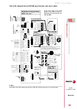
Connection diagrams
354
10.
CON
N
ECTION DIAGRAMS
El
ectri
cal cabin
et. Dia
grams
332
DDS
HARDWARE
Ref.1310
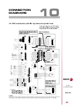
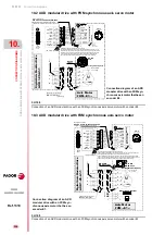
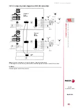
10.7 Electrical cabinet. Diagrams
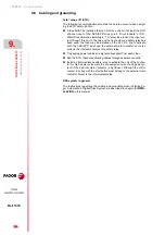
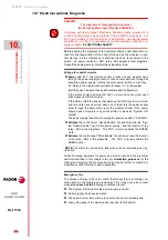
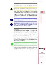
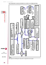
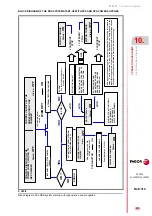
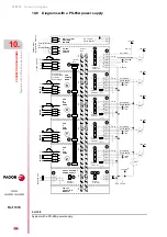
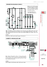
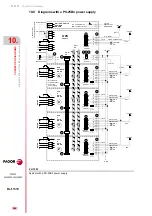
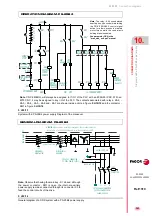
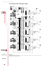
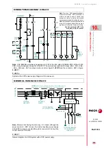
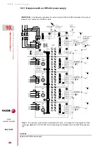
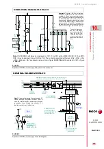
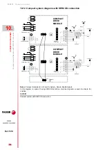
Before showing the diagrams of the electrical cabinet, described later on,
read this brief explanation of the actions followed by the modules on sys-
tem start-up. All the references to electrical devices, for example to the
switch - S1, power contactor - KM1, relay - KA3 appear in later diagrams.
Consult these diagrams to interpret the explanatory texts.
Voltage for control circuits
Power
with 24 V the internal control circuits of each modular drive
through the power supply module or of each compact drive through its
integrated power supply, closing the main power switch or main key -
S1. Refer to the diagrams shown later to locate - S1 in the system.
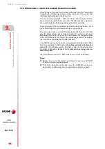
Internally, each module checks its hardware and configuration.
If the status of each drive is OK and no errors have occurred, each
drive closes its DR.OK contact.
If the status of
all
the drives that make up the DDS system is correct
and no errors have occurred, each one of them lets the power supply
know through the internal bus (only the modular drives). If the power
supply does not register any errors either, it closes its “System OK”
contact.
The power supply then starts charging the power bus with a “Soft-Start”.
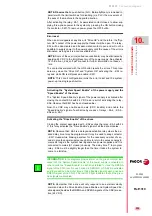
Activate
the control input “Speed Enable” of each drive and the “Sys-
tem Speed Enable” input of the power supply - see the location of the
relay - KA2 in the diagrams. - The CNC, in turns, enables the SPENA
mark -.
Activate
the control input “Drive Enable” of each drive - see the location
of the relay - KA3 in the diagrams. - The CNC, in turns, enables the
DRENA mark -.
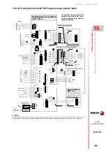
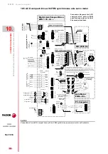
All the following diagrams for power and control circuits in the electrical
cabinet described in this chapter are only
orientation purposes
for the
technician designing the machine and they may be further completed or
simplified at will according to each application.
Emergency line
The purpose of relay - KA1 is to confirm that the system is in running con-
dition both mechanically and electrically. This relay closes its contact
when
all and each of the
following conditions are met:
The System_OK contact of the power supply is closed.
No emergency has been activated.
The spindle motor temperature is correct (it does not overheat) and
none of the axes of the machine has reached its limit switch.
DANGER.
The diagrams of this chapter do not meet
the European Machinery Directive 2006/42/EC.
Complying with the European Machinery Directive usually requires PL d
or SIL 2 (milling machines and lathes). The AXD/SPD reaches PL d or
SIL 2 (see models in the Declaration of Conformity). An external safety
controller PL d or SIL 2 is necessary as well as bearing in mind the con-
cepts in chapter
NOTE.
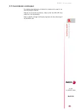
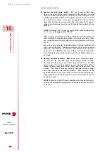
The motor is now ready to follow the velocity command given by
the CNC.
Содержание DDS
Страница 1: ...DRIVE DDS Hardware manual Ref 1310...
Страница 6: ...I 6 DDS HARDWARE Ref 1310...
Страница 9: ......
Страница 10: ......
Страница 11: ......
Страница 12: ......
Страница 16: ...16 Ref 1310 DDS HARDWARE...
Страница 30: ...1 DESCRIPTION 30 Description DDS HARDWARE Ref 1310...
Страница 94: ...2 POWER SUPPLIES 94 Power supplies DDS HARDWARE Ref 1310...
Страница 188: ...3 DRIVE MODULES 188 Drive modules DDS HARDWARE Ref 1310...
Страница 204: ...4 AUXILIARY MODULES 204 Auxiliary modules DDS HARDWARE Ref 1310...
Страница 232: ...SELECTING CRITERIA 5 232 Selection criteria DDS HARDWARE Ref 1310...
Страница 266: ...7 CABLES 266 Cables DDS HARDWARE Ref 1310...
Страница 312: ...8 INSTALLATION 312 Installation DDS HARDWARE Ref 1310...
Страница 326: ...9 FUNCTIONAL SAFETY 326 Functional safety DDS HARDWARE Ref 1310...
Страница 354: ...10 CONNECTION DIAGRAMS 354 Connection diagrams DDS HARDWARE Ref 1310...
Страница 378: ...12 SALES REFERENCES 378 Sales references DDS HARDWARE Ref 1310...
Страница 384: ...13 COMPATIBILITY 384 Compatibility DDS HARDWARE Ref 1310...
Страница 385: ......

