Hardware configuration.
CNC 8070
HEAT DISSIPATION. CENTRA
L UNIT (CPU)
EN
CLOSURE (ETX
3.
·39·
(R
EF
: 1911)
3
HEAT DISSIPATION. CENTRAL UNIT (CPU) ENCLOSURE
(ETX PLATFORM).
The enclosure must be designed to ensure an ambient temperature of 45 ºC (113 ºF) and
while the unit is running, the enclosure temperature must not exceed 55 ºC (131 ºF). To
ensure that it does not exceed this temperature, the enclosure must meet the following
requirements.
• The enclosure must have enough surface inside to evacuate the heat generated inside
and keep the ambient conditions within the working temperature range.
• The enclosure must respect the minimum distances recommended between the
enclosure walls and the central unit to let the air flow and improve heat dissipation.
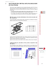
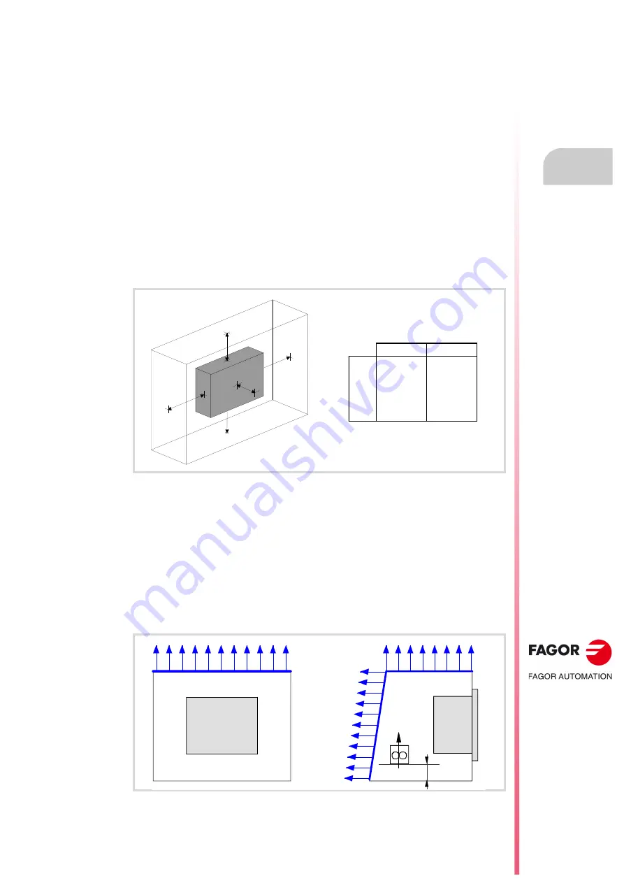
Minimum gaps recommended between the enclosure walls and
the central unit.
To ensure that it does not exceed this temperature, respect the recommended minimum gap
between the sides of the enclosure and the central unit.
To ensure the required ambient conditions, the enclosure must have an air input next to the
cables and an air output next to the fan. In this case, install fans to ventilate the enclosure
and keep the temperature within the allowed limits.
Keep the enclosure clean. Anti-dust filters should be installed at the air inputs and outputs.
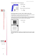
Understanding the calculation of the surface needed for heat
dissipation
The expressions have been obtained for an enclosure having a 2 mm wall and made out
of aluminum. When using internal ventilation, the fan must be located 30 mm off the bottom.
mm
inch
a
100
3,937
b
100
3,937
c
100
3,937
d
150
5,906
e
50
1,969
A
B
C
D
E
Ti
Ta
A
P
30mm
Q
Содержание CNC 8070
Страница 1: ...Ref 1911 8070 CNC Hardware configuration...
Страница 8: ...BLANK PAGE 8...
Страница 14: ...BLANK PAGE 14...
Страница 18: ...BLANK PAGE 18...
Страница 22: ...BLANK PAGE 22...
Страница 24: ...BLANK PAGE 24...
Страница 26: ...BLANK PAGE 26...
Страница 28: ...Hardware configuration CNC 8070 1 PREVIOUS INFORMATION 28 REF 1911...
Страница 38: ...Hardware configuration CNC 8070 2 CONFIGURATION General diagram for U60 Q7 A platform 38 REF 1911...
Страница 94: ...Hardware configuration CNC 8070 6 CENTRAL UNIT MONITOR Q7 A PLATFORM 94 REF 1911 C70 15AT...
Страница 184: ...Hardware configuration CNC 8070 8 LCD 15SVGA PASSIVE MONITOR LCD15 SVGA Overall connection 184 REF 1911...
Страница 272: ...Hardware configuration CNC 8070 18 INSTALLING A SENSOR FOR GAP CONTROL LASER MODEL 272 REF 1911...
Страница 273: ...Hardware configuration CNC 8070 273 User notes REF 1911...
Страница 274: ...Hardware configuration CNC 8070 274 User notes REF 1911...
Страница 275: ...Hardware configuration CNC 8070 275 User notes REF 1911...

