Hardware configuration.
CNC 8070
17.
INSTALLING AND CONFIGURING
A THIN CLIENT
(EPATEC
Con
fig
uring
the
Thin
Cl
ien
t.
·268·
(R
EF
: 1911)
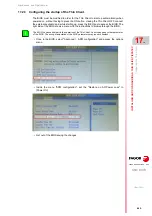
17.2.2 Configure the communication between the CNC and the Thin Client.
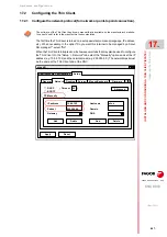
The Thin Client comes with a VNC client software. To configure the VNC start command,
select the tab Configuration> New > Local and define the following data.
Together with the command, it launches the IP address to which the Thin Client is connected.
The address may be changed from Configuration > Edit > Local, in the Parameter window.
Name
VNC (or the desired name)
Application
Custom
Parameter
vncviewer10.0.7.250:0 -fullscreen (IP address of the CNC)
Start automatically
Select this option with a value of 5 s (illustrative value).
Application restart
Select this option so the Thin Client tries to re-establish
communication without having to restart the system in case of
communication loss for some time (because the Ethernet cable
has been disconnected, for example).
The purpose of the "Start automatically" parameter is to start the VNC client of the Thin Client after
the VNC of the CNC has been started up. The value of this parameter depends largely on how both
devices, central unit and Thin Client, start up. If both elements start up at the same time or the Thin
Client starts before the VNC server is available at the CNC, the VNC customer of the Thin Client cannot
be connected and it will issue a connection error or data reading error. In this case, the time set for
parameter "Start automatically" will have to be increased.
If the startup of the Thin Client depends on the CNC being started up first (e.g. condition the startup
of the Thin Client to a PLC output), this "Start automatically" parameter could be set to 0 (zero).
i
eLux NG
Apply
Finish
Name
Application
vnc
0.0.7.250:0-fullscreen
Local
Custom
Start automatically after
Desktop icon
Application restart
Hidden
5 s
Parameter
Содержание CNC 8070
Страница 1: ...Ref 1911 8070 CNC Hardware configuration...
Страница 8: ...BLANK PAGE 8...
Страница 14: ...BLANK PAGE 14...
Страница 18: ...BLANK PAGE 18...
Страница 22: ...BLANK PAGE 22...
Страница 24: ...BLANK PAGE 24...
Страница 26: ...BLANK PAGE 26...
Страница 28: ...Hardware configuration CNC 8070 1 PREVIOUS INFORMATION 28 REF 1911...
Страница 38: ...Hardware configuration CNC 8070 2 CONFIGURATION General diagram for U60 Q7 A platform 38 REF 1911...
Страница 94: ...Hardware configuration CNC 8070 6 CENTRAL UNIT MONITOR Q7 A PLATFORM 94 REF 1911 C70 15AT...
Страница 184: ...Hardware configuration CNC 8070 8 LCD 15SVGA PASSIVE MONITOR LCD15 SVGA Overall connection 184 REF 1911...
Страница 272: ...Hardware configuration CNC 8070 18 INSTALLING A SENSOR FOR GAP CONTROL LASER MODEL 272 REF 1911...
Страница 273: ...Hardware configuration CNC 8070 273 User notes REF 1911...
Страница 274: ...Hardware configuration CNC 8070 274 User notes REF 1911...
Страница 275: ...Hardware configuration CNC 8070 275 User notes REF 1911...


