DC Servo Drive System Manual V
er: 0009
DC - 14/32
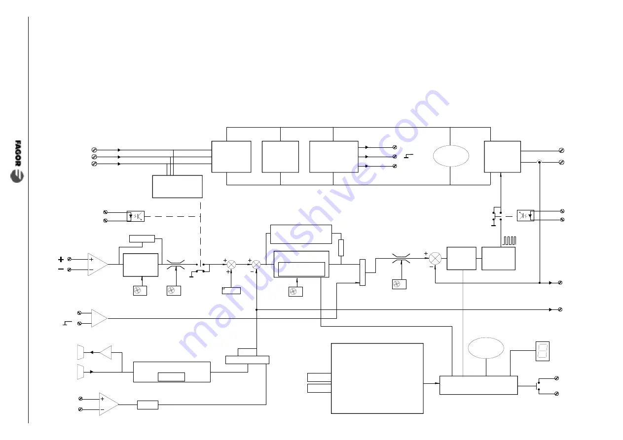
2
.5
INTERNAL
OPERA
TION
DIAGRAM
Ballast.
Rectifer
Power
stage.
PWM
L3
L1
L2
CURRENT
Pin 12
MOTOR
OUTPUT
POWER
INPUT
Ramp
generator
Pin 5
Pin 6
VEL
Pin 8
Pin 9
Max.
Speed
Max. Current
Limit
J2 a b c
CURR
Pin 7
Pin 4
Acc/Dec
Ramps
PI. Gain
J3
a
b
Speed PI
J1
a b c d e
ENCODER
INPUT
ENCODER
OUTPUT
A
Protections:
Motor Insulation Fault
Feedback Error
Drive Overtemperature
Motor Overload
Drive Overcurrent
Drive Overvoltage
Undervoltage
Logic circuits for
diagnosis & control.
STATUS
DR.OK
Pin 1
Pin 2
Pin 3
Internal
supply
-10V
+10V
Pin 16
Pin 17
TACHO
INPUT
DRIVE
SPEED
Pin 13
Overspeed
Control
Offset
RTV1
Frequency / Voltage
RIT
RAPT
J4
a
b
c
A
Pin 15
Pin 15
Pin 14
PWM
Control
Current
PI
Power-down
detection
COMMON
COMMON
RAD1
CAD1
RAP1
CAI1
RAJFV
Bus
Voltage
VEL
VELOCITY
Pin 11
Bus
Voltage


