


216
6.2 Connectors
The Detector has a total of 6 connectors on the top or shaft end:
Connector
Meaning
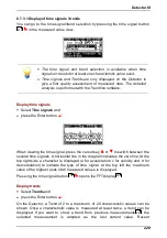
BNC connectors 1/2
Each connection accommodates one activ e sensor w ith ex citation current (4.7
mA).
Port 1 is alw ay s used for CM measurements. Port 2 can be used for tw o-plane
balancing measurements.
Because the Detector is a single-channel device it cannot perform
measurements at both ports simultaneously!
3.5 mm jack
Connection for headset or analog recording dev ice. The headset connection can
only be activ ated v ia the "Single measurements" menu.
9-pin sub-D socket
Connection for a serial data line to facilitate ex change of data w ith the computer
(RS 232 interface).
AUX socket
(8p socket)
A temperature sensor or trigger sensor may be connected to the AUX socket. It
is assigned as follow s:
1: Output
12 V supply for trigger sensors (12 V against DGND)
2: Input
GND Temperature sensor
3: Input
+ Temperature sensor
4: Output
DGND
5: Input
+ Trigger sensor signal
6: Input
GND Trigger sensor signal
7: Output
5 V supply for trigger sensors (5 V against DGND)
8: -
Not used
Charging port
(4-pin socket next to
serial port)
For connection of battery charger.