background image

8

1

2

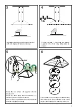
Draw a vertical line on the supporting wall as high as practical, at the center of the area in which 

the hood will be installed. 

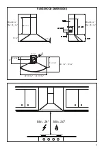
Draw a horizontal line at where the bottom edge of the hood will be located as indicated in the figure 

that is a minimum of 24" - 30" above cooking surface.

Place a Upper bracket 7.2.1 on the wall as shown about 1 

1/8

" from the ceiling or upper limit, aligning the 

centers(notch) with the vertical reference line and mark the wall at the centers of the holes in the bracket.

Place the other bracket 7.2.1 on the wall as shown, below the first bracket, at the height of the upper 

chimney section supplied and aligning the centers(notch) with the vertical line.

Mark the wall at the centers of the holes in the bracket.

Place bracket 7.1 as shown 4” 

5/16

 from the vertical reference line and 7” 

1/2

 above the horizontal 

reference line.

Mark the centres of the holes in the bracket and repeat this operation on the other side.

Drill ø 5/16" holes at all the centers points marked (point 1,2,3,4,5,6,7,8) as shown. 

Fix the 2 brackets 7.2.1 using the 12a screws supplied with wall plugs (purchase separately).

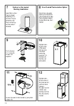
Installation Instructions

´

>


x8

x8

‘´


´

´

Содержание TENDER TEND30SSV

Страница 1: ...30SSV TEND36SSV TEND30BSV TEND36BSV TENDER Installation Instructions Use and Care Information Instructions d installation Utilisez et d entretien Instrucciones de instalaci n Informaci n de uso y cuid...

Страница 2: ...with your back to an exit Based on Kitchen Firesafety Tips published by NFPA WARNING TO REDUCE THE RISK OF FIRE OR ELECTRIC SHOCK do not use this fan with any solid state speed control device WARNING...

Страница 3: ...the flow of combustion and ventilation air Failure to follow venting requirements may result in a fire WARNING VENTING REQUIREMENTS Determine which venting method is best for your application Ductwor...

Страница 4: ...or grounding circuit could result in electrical shock Check with a qualified electrician if you are in doubt as to whether the rangehood is properly grounded Failure to follow electrical requirements...

Страница 5: ...5 RANGEHOOD DIMENSIONS Min 24 Min 30 9 7 16 22 1 16 Min 28 3 4 Max 43 5 16 Min 28 3 4 Max 43 5 16 13 16 5 7 8 14 13 16 18 17 8 19 5 8 29 15 16 35 11 16 3 15 16 9 8 1 4...

Страница 6: ...6 Screws 1 8 x 3 8 12d 2 Screws 3 16 x 1 Qty Documentation 1 Instruction Manual Available Accessories Direct Connect Wiring Box sku WIREBOX Activated Charcoal Filter sku FILTER1 Long Lasting Activate...

Страница 7: ...ed Recirculation Ducted Venting Installation Requires purchase of Activated Charcoal Accessory Horizontal Vertical 6 H I Install Damper that is included with the Hood before connecting to the ductwork...

Страница 8: ...eholesinthebracket Place the other bracket 7 2 1 on the wall as shown below the first bracket at the height of the upper chimney section supplied and aligning the centers notch with the vertical line...

Страница 9: ...ody fixing holes as shown Screw the two screws 12d supplied onto the brackets 7 1 Hook the hood body onto the bracket 7 1 centering it around the vertical line Use the adjusting screws 12d underneath...

Страница 10: ...Ensure that the activated charcoal filters have been inserted 12 Fix the bracket 7 2 1 using the screws 12a supplied 11 Slightly widen the two sides of the lower section and hook them between the uppe...

Страница 11: ...tely understood or if doubt exists as to whether the appliance is properly grounded Do not use an extension cord If the power supply cord is too short have a qualified electrician install an outlet ne...

Страница 12: ...tivate the intensive speed which is timed to run for 6 minutes At the end of this time it will automatically return to the speed set before Suitable to deal with maximum levels of cooking fumes L Ligh...

Страница 13: ...ncy of the filter itself Replace taking care to ensure that the handle faces forwards No water can be present in filters before installing back in hood Replacing Activated Charcoal Filter Thefilterisn...

Страница 14: ...14 Wiring Diagram 120V 60Hz...

Страница 15: ...om accident alteration misuse abuse fire flood acts of God improper installation installation not in accordance with electrical or plumbing codes or Faber documentation or use of products not approved...

Страница 16: ...nevoiedesortiesetrouvederri revouspendantquevous teignezlesflammes D apr sleguide KitchenFiresafetyTips publi parlaNFPAaux tats Unis AVERTISSEMENT POURR DUIRELERISQUED INCENDIEOUDECHOC LECTRIQUE n uti...

Страница 17: ...renier ou un autre endroit ferm N UTILISEZ PAS un clapet de s cheuse mural de 4 po Il n est pas recommand d utiliser des conduits flexibles N ENTRAVEZ PAS le flux de l air de combustion et de ventilat...

Страница 18: ...sible dans le circuit neutre ou de mise la terre peut entra ner un choc lectrique Consultez un lectricien qualifi si vous n tes pas certain de la mise la terre de la hotte Le non respect des exigences...

Страница 19: ...19 DIMENSIONS DE LA HOTTE 9 7 16 22 1 16 Min 28 3 4 Max 43 5 16 Min 28 3 4 Max 43 5 16 13 16 5 7 8 14 13 16 18 17 8 19 5 8 29 15 16 35 11 16 3 15 16 9 8 1 4 Min 24 Min 30...

Страница 20: ...12d 2 Vis3 16 x1 Qt Documentation 1 Moded emploi Accessoires disponibles Bo tier de connexion directe no d article WIREBOX Filtre charbon actif No d article FILTER1 Filtre charbon actif de longue dur...

Страница 21: ...la raccorder aux conduits Pour installation avec ventilation canalis e uniquement Choisissez la m thode de canalisation Exige l achat de l accessoire charbon actif Hori zontale Verticale Sans canalis...

Страница 22: ...icale Marquez l emplacement du centre des trous de la bride sur le mur Placez la bride 7 2 1 sur le mur comme illustr sous la premi re bride la hauteur de la section sup rieure de la chemin e fournie...

Страница 23: ...hotte comme illustr Posez les deux vis 12d sur les brides 7 1 Engagez le b ti de la hotte sur la bride 7 1 en le centrant autour de la ligne verticale Utilisez les vis de r glage 12d sous la hotte po...

Страница 24: ...de 6 au clapet de toiture ou au clapet mural puis raccordez les conduits Installation avec canalisation verticale ou horizontale cartez l g rement les deux c t s de la chemin e sup ri eure et engagez...

Страница 25: ...rdon d alimentation est trop court demandez un lectricien qualifi d installer une prise proximit de l appareil INSTALLATION LECTRIQUEAVEC BO TIER DE CONNEXION EN OPTION Pour une installation avec conn...

Страница 26: ...c pendant environ 2 secondes pour activer la vitesse intensive pour une dur e de 6 minutes Apr s ce d lai la vitesse retournera automatiquement la vitesse s lectionn e pr c demment Utile pour contrer...

Страница 27: ...vous assurant que la poign e se trouve vers l avant Aucune eau ne peut tre pr sente dans les filtres avant la r installation dans la hotte Remplacement du filtre charbon actif Le filtre n est pas lav...

Страница 28: ...28 Sch ma de c blage 120V 60Hz...

Страница 29: ...es d coulant d un accident d une modification de l utilisation incorrecte ou abusive d un incendie d une inondation d un cas de force majeure d une installation inad quate d une installation non confo...

Страница 30: ...REDUCIRELRIESGODEDESCARGAEL CTRICAOINCENDIO nouse este ventilador con ning n dispositivo de control de velocidad de estado ADVERTENCIA PARA REDUCIR EL RIESGO DE INCENDIOS DESCARGAS EL CTRICAS O LESION...

Страница 31: ...s espacios angostos o garajes TODAS LAS ABERTURAS DE LA PARED Y EL PISO DONDE EST INSTALADA LA CAMPA NA SE DEBEN SELLAR Esta campana requiere al menos 24 de espacio libreentre la parte inferior de la...

Страница 32: ...tierra podr a provocar una descarga el ctrica Consulte con un electricista calificado si tiene dudas acerca de si la campana est correctamente conectada a tierra El incumplimiento de los requisitos el...

Страница 33: ...33 9 7 16 22 1 16 Min 28 3 4 Max 43 5 16 Min 28 3 4 Max 43 5 16 13 16 5 7 8 14 13 16 18 17 8 19 5 8 29 15 16 35 11 16 3 15 16 9 8 1 4 DIMENSIONES DE LA CAMPANA Min 24 Min 30...

Страница 34: ...te 12a 8 Tornillos 3 16 x 1 3 4 12c 6 Tornillos 1 8 x 3 8 12d 2 Tornillos 3 16 x 1 Cdad Documentaci n 1 Manual de instrucciones Accesorios disponibles Caja de cableado de conexi n directa n mero sku C...

Страница 35: ...cluye con la campana antes de la conexi n a la red de conductos Solo para instalaci n de ventilaci n con conductos Elija su m todo de conducci n Sin conductos recirculaci n Instalaci n de ventilaci n...

Страница 36: ...en el soporte Coloque el otro soporte 7 2 1 en la pared como se muestra debajo del primer soporte a la altura de lasecci nsuperiordelachimeneasuministradayalineandoloscentros muesca conlal neavertica...

Страница 37: ...campana comosemuestra Atornille los dos tornillos 12d suministrados en los soportes 7 1 Engancheelcuerpodelacampanaenelsoporte 7 1 centr ndolo alrededor de la l nea vertical Use los tornillos de ajust...

Страница 38: ...los filtros de carb n activado se hayan insertado 12 Fije el soporte 7 2 1 utilizando los tornillos 12a suministrados 11 Agrande ligeramente los dos lados de la secci n inferior y enganche entre la se...

Страница 39: ...de conexi n a tierra no se comprenden completamente o si existe una duda acerca de si el equipo est correctamente conectado a tierra No utilice un cable de extensi n Si el cable de alimentaci n es dem...

Страница 40: ...2 segundos para activar la velocidad intensiva que est programada para ejecutarse durante 6 minutos Al final de este tiempo volver autom ticamente a la velocidad establecida anteriormente Adecuado par...

Страница 41: ...rarse de que la manija mire hacia adelante Aseg rese de eliminar toda el agua y cualquier otro l quido antes de volver a instalar los filtros despu s de la limpieza Reemplazo del filtro de carb n acti...

Страница 42: ...42 Diagrama de cableado 120V 60Hz...

Страница 43: ...r est n garantizados contra cualquier defecto de materiales o mano de obra para el comprador original por un per odo de 1 a o a partir de la fecha de compra original requiere prueba de compra Esta gar...

Страница 44: ...991 0556 775_03 190206 D00005238_02...

Отзывы: