10
E-SLIM LINEAR 2200/450 l
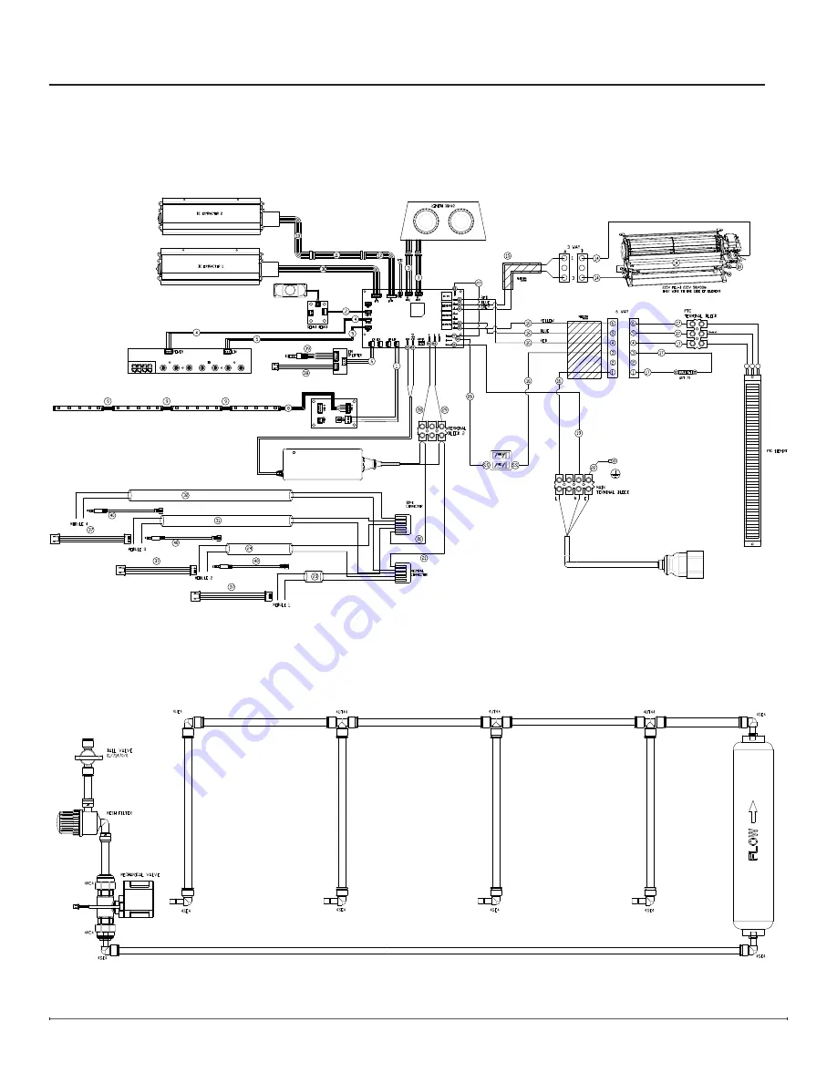
Wiring and Plumbing Diagrams
Firebox Wiring Diagram
Plumbing Diagram
To Module
Страница 1: ...ttempting to install or use this electric fireplace Always comply with the warnings and safety instructions contained in this manual to prevent personal injury or property damage 40012202 2306 E SLIM...
Страница 2: ...acement 14 LED Driver Board Replacement 14 Hidden Touch Controls Housing Replacement 15 Power Adaptor Replacement 16 Sound Board and Speaker Replacement 17 Top LEDs Replacement 18 LIN Splitter Board R...
Страница 3: ...00RP 11 Top LED Strip Holder X 9602770200RP 12 Electro mechanical Valve 06023853 13 Module Wire Harness Set X 9602790100RP 14 Temperature Sensor NTC 06023679 15 Front Glass 04 06 001 148 16 Media Plat...
Страница 4: ...older X 9602770200RP 12 Electro mechanical Valve 06023853 13 Module Wire Harness Set X 9602790100RP 14 Temperature Sensor NTC 06023679 15 Front Glass 04 06 001 149 16 Media Plate X 9602660200RP 17 Upp...
Страница 5: ...older X 9602770200RP 12 Electro mechanical Valve 06023853 13 Module Wire Harness Set X 9602790100RP 14 Temperature Sensor NTC 06023679 15 Front Glass 04 06 001 150 16 Media Plate X 9602660300RP 17 Upp...
Страница 6: ...602890100RP 11 Heating Element 06023619 12 Fill Cap Assembly 01 71499 0 13 Top Cover Assembly 06023618 14 Transducer 06023368 15 Water Reservoir X SP01 19138 0 16 Bluetooth Harness X 9601080100RP 17 S...
Страница 7: ...7 Module Wiring Diagrams FAN A secondary transducer is optional Only one transducer is needed for operation...
Страница 8: ...8 Wiring and Plumbing Diagram E SLIM LINEAR 1200 450 l Firebox Wiring Diagram Plumbing Diagram To Module To Module...
Страница 9: ...9 E SLIM LINEAR 1700 450 l Wiring and Plumbing Diagrams Firebox Wiring Diagram Plumbing Diagram To Module To Module To Module...
Страница 10: ...10 E SLIM LINEAR 2200 450 l Wiring and Plumbing Diagrams Firebox Wiring Diagram Plumbing Diagram To Module To Module To Module To Module...
Страница 11: ...ce or take a picture of each wire and the location of the wire to differentiate the connections Tools Required Phillips Head Screwdriver Suction Cup to assist in lifting glass 1 Remove the front glass...
Страница 12: ...ectors Figure 4 4 Lift the heater assembly upward and pull it forward to unhook and remove the defective heater assembly 5 Position the new heater assembly on the back hooks 6 Plug in the socket conne...
Страница 13: ...l with the extractor fan can be taken out of the chassis for easy servicing 5 Locate and remove the screws securing the air duct 6 Locate and remove the 4 screws securing the extractor fan to the pane...
Страница 14: ...crews removed previously LED Driver Board Replacement Tools Required Phillips Head Screwdriver 1 Follow instructions for preparing for service Page 11 2 Remove the 7 screws that secure the top panel f...
Страница 15: ...replacing the hidden touch controls hardware The replacement housing does not require transfering the wires NOTE The panel is supported by hooks in the back 4 Detach the hidden touch controls assembl...
Страница 16: ...disconnect from the terminal block use a precision screwdriver loosen do not remove the screws that secure the wires to free them 6 Detach the defective power adaptor from the bracket unplugging the...
Страница 17: ...3 To replace the speaker Remove the 4 screws that secure the speaker and unplug it from the board Secure the new speaker and plug it in 4 To replace the sound board Clip the standoffs using side cutte...
Страница 18: ...Tools Required Phillips Head Screwdriver Pliers 1 Follow the instructions for preparing for service Page 11 2 Remove the front glass by lifting it up and tilting out using the suction cups to assist...
Страница 19: ...placement of the connections for the installation of the new module 7 Disconnect the piping from the solenoid valve by pushing the white tab in and pulling the tube out simultaneously 8 Remove the tw...
Страница 20: ...k to be replaced Figure 17 5 Disconnect the wire connections from the original terminal block and install it on the new one 6 Replace the terminal block in the original position the terminal block is...
Страница 21: ...18 6 Locate the fan assembly Figure 18 7 Trace the control wires to the main control board and disconnect 8 Install and connect the new fan assembly 9 Reinsert the electronics assembly CAUTION Ensure...
Страница 22: ...ess brown wire from main switch to main control board with in line fuse 7 Replace current wire harness with new wire harness NOTE A flat head screwdriver can be used to gently pry between the end of t...
Страница 23: ...hey snap in place Figure 14 8 Disconnect the tranducer and lift out the water reservoir 9 Locate the water level sensor Figure 20 10 Disconnect the control wire for the water level sensor from the mai...
Страница 24: ...l board Figure 21 7 Transfer the wires from the old board to the new board NOTE A flat head screwdriver can be used to gently pry between the end of the connector and the switch to release the wires 8...
Страница 25: ...nt assembly out of the unit 8 Disconnect the element from the main control board 9 Remove the element from the mounting bracket and install the new element 10 Attach the new element wire to the main c...
Страница 26: ...ply wires from the terminal block and main control board NOTE A flat head screwdriver can be used to gently pry between the end of the connector and the switch to release the wires 8 Remove the old po...
Страница 27: ...24 6 Trace and disconnect the control wire for the solenoid back to the main control board 7 Remove the two screws from the front face of the bracket to release the valve Figure 25 8 Disconnect the pl...
Страница 28: ...nd to commands given from the remote control N A The batteries in the remote control are dead or installed incorrectly Replace remote control batteries Ensure batteries are installed with facing up Re...
Страница 29: ...EDs are defective Replace defective LED strip s Flame is not illuminated N A Flame light has been turned off using the app Adjust the flame settings from app remote or hidden touch controls Loose conn...
Страница 30: ...D33 Main PCB overheating See below Unit was turned on and off too many times in a short period Put the unit in standby and allow it to cool for 30 minutes Heater exhaust blockage Turn unit off from po...
Страница 31: ...Incorrect LIN splitter connections Ensure connections are placed correctly on the LIN splitter board Defective LIN splitter board Replace LIN splitter board CD51 Low water level in one of the water re...