background image

Connecting the cables and other hardware

After you have installed the chassis into the rack, connect the cables and other hardware.

Note: Serial (hard-wired) failover is not currently supported between VIPRION chassis. If you would like
to set up device service clustering (DSC

®

), previously known as a redundant system configuration, you must

configure network failover. For more information, see BIG-IP

®

Device Service Clustering: Administration.

1.

Connect an Ethernet cable to the MGMT port if you are using the default network configured on the
management interface.

2.

Connect the platform to a serial console server.

Important: In the event that network access is impaired or not yet configured, the serial console might
be the only way to access the chassis. F5

®

strongly recommends that you perform all installations and

upgrades using the serial console, as these procedures require reboots, in which network connectivity
is lost temporarily.

Connect the serial console cable supplied by F5 to the CONSOLE port.

Note: The default serial port settings are 19200, n, 8, 1.

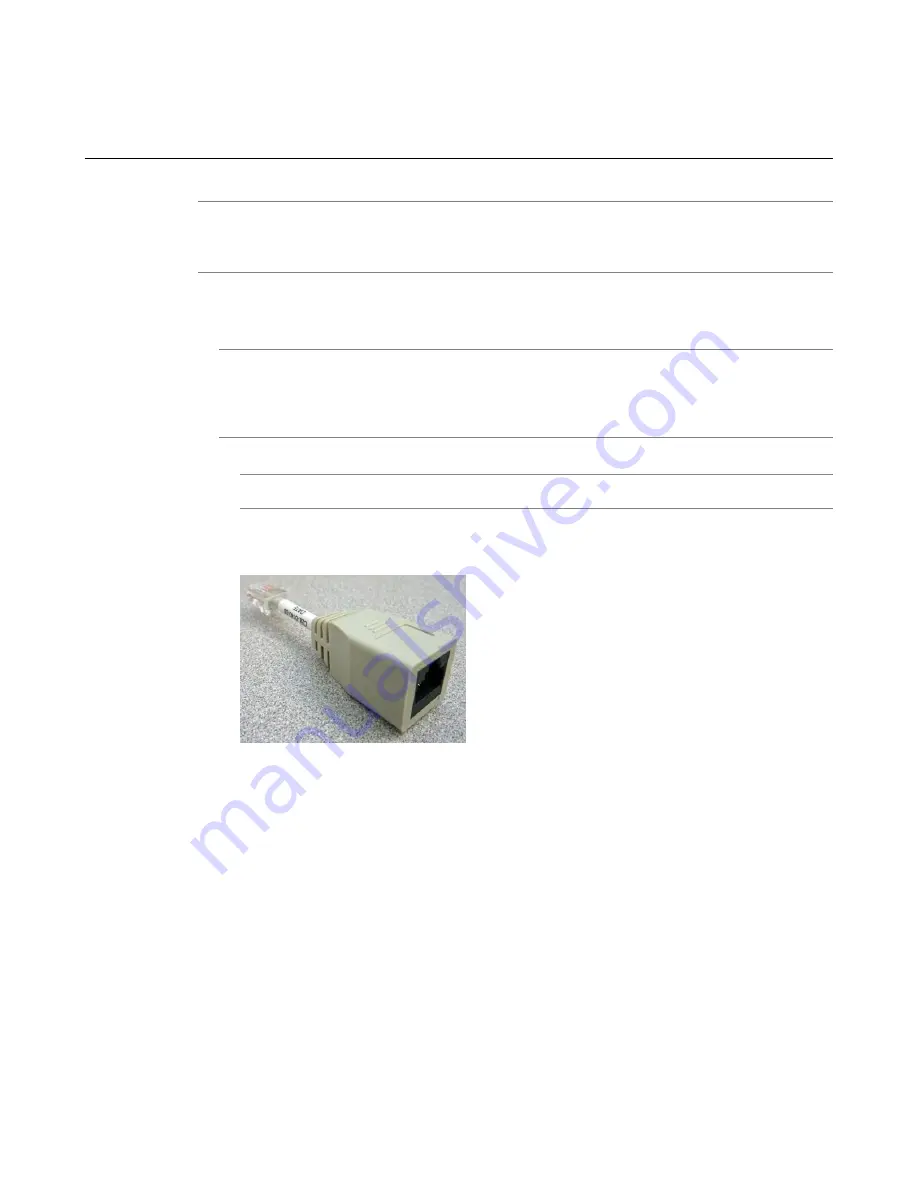
Connect the RJ45F to RJ45M rolled serial adapter to the CONSOLE port if you are connecting the
system to a serial console server with a standard CAT5 cable, and then connect the CAT5 cable to
the adapter. The adapter provides the appropriate pinout connection to your equipment.

Figure 12: The RJ45F to RJ45M rolled serial (pass-through) adapter

3.

If you have not already done so, power on the chassis.

You can now assign a cluster IP address to the system, and then license and provision the software.

Optionally, you should run the latest version of the qkview utility. This utility collects configuration and
diagnostic information about your system into a single file that you can provide to F5 Support to aid in
troubleshooting. For more information, see

http://support.f5.com/kb/en-us/solutions/public/1000/800/sol1858.html

.

39

Platform Guide: VIPRION

®

2400

Содержание VIPRION 2400

Страница 1: ...Platform Guide VIPRION 2400 MAN 0344 05 ...

Страница 2: ......

Страница 3: ...s 16 Defining custom alerts 16 Platform interfaces 17 About blade interfaces 17 About 40GbE QSFP interfaces 17 About managing interfaces 19 Network interface LED behavior 21 Transceiver module specifications 22 Cable pinout specifications 22 Always On Management 23 AOM Command Menu options 23 Accessing the AOM Command Menu from the serial console 24 Capturing a blade console 24 Platform Installati...

Страница 4: ...s from the LCD 40 Configuring the cluster IP address using the config utility 42 Configuring the cluster IP address using tmsh 42 Licensing the platform 42 Verifying blade availability 43 Platform Maintenance 45 About maintaining the platform 45 About AC power supplies 45 Removing a power supply 46 Installing a power supply 46 About DC power supplies 47 Removing a power supply 48 Installing a DC p...

Страница 5: ...nd altitude specifications 66 China RoHS Requirements 69 RoHS declaration 69 Hazardous substance levels for China 69 Repackaging Guidelines 73 About repackaging the platform 73 Repackaging the chassis 73 Repackaging a blade 75 Returned Material Data Security Statement 79 About returned material data security 79 About memory technologies used in F5 equipment 79 Volatile memory 79 Battery backed vol...

Страница 6: ...6 Table of Contents ...

Страница 7: ...SIGN F5 Networks F5 SalesXchange DESIGN F5 Synthesis f5 Synthesis F5 Synthesis DESIGN F5 TechXchange DESIGN Fast Application Proxy Fast Cache FCINCO Global Traffic Manager GTM GUARDIAN iApps IBR iCall iControl iHealth Intelligent Browser Referencing Intelligent Compression IPv6 Gateway iQuery iRules iRules OnDemand iSession L7 Rate Shaping LC Link Controller LineRate LineRate Point LineRate Precis...

Страница 8: ...alled and used in accordance with the instruction manual may cause harmful interference to radio communications Operation of this equipment in a residential area is likely to cause harmful interference in which case the user at his own expense will be required to take whatever measures may be required to correct the interference Any modifications to this device unless expressly approved by the man...

Страница 9: ...are needed to manage network traffic and a chassis which houses the blades The VIPRION 2400 platform supports either AC or DC power If you ordered DC power as a factory option the platform comes pre installed with DC power supplies If you ordered DC power supplies from F5 Networks as an upgrade to an AC powered platform you have to switch out the AC power supplies for DC power supplies Important T...

Страница 10: ...a VIPRION 2400 chassis These blades comprise a group known as a cluster The chassis includes blanks in the slots where blades are not installed Blanks must be installed in all unused slots as they help ensure proper airflow within the chassis and EMI compliance of the unit Figure 3 Front view of the B2100 B2150 blade 1 Captive screws 2 SFP ports 8 3 Console port 4 Serial hard wired failover port 5...

Страница 11: ...th VIPRION 2000 Series platforms Figure 5 USB LCD module Using the USB LCD module You can connect a USB LCD module to the primary blade in a VIPRION 2000 Series chassis and use the module to configure and manage the unit without attaching a console or network cable 1 Insert the plug into one of the two USB ports located on the front of the primary blade the blade on which the Primary LED is lit Th...

Страница 12: ...erts on the screen before you can use the LCD module About LCD menus There are three menus on the LCD module You can configure the display options to meet your needs Options menu You can use the Options menu to adjust the display properties of the LCD module Description Option Enables checked or disables unchecked the heartbeat panel on the LCD This heartbeat does not affect the failover mechanism...

Страница 13: ...naging the cluster Commit saves your changes Cluster Mbrs Select from these suboptions Configures the management IP addresses of the blades within the cluster Blade 1 4 Mgmt Blade Mgmt IP sets the management IP address of the selected blade within the cluster Commit saves your changes Indicator LEDs The VIPRION 2400 platform includes indicator LEDs in three locations on the individual blades on th...

Страница 14: ...LED SEC Primary LED PRI System state Off None Green solid Off None Off None Active mode Off None Off None Off None Off None Powered off Blade LED status conditions The blade LEDs indicate specific operating conditions such as when a blade is shut down reset or not properly seated Alarm LED Status LED Secondary LED Primary LED Blade state Off None Green blinking with traffic Green blinking with tra...

Страница 15: ...failure DC failure Any other power supply faults such as fan failure indicated by the FAIL LED Green status when the fan tray is powered and the power supply is fully functional AC and DC are OK no other faults indicated by the FAIL LED DC power supply indicator LEDs The DC power supply LEDs indicate the status of the power supply and power input Status LED Indicates that DC input voltage is opera...

Страница 16: ...alert conf file 1 Open a command prompt on the system 2 Change to the config directory cd config 3 Using a text editor such as vi or Pico open the config user_alert conf file 4 Add these lines to the end of the file alert BIGIP_MCPD_MCPDERR_POOL_MEMBER_MON_DOWN Pool member monitor status down snmptrap OID 1 3 6 1 4 1 3375 2 4 0 10 lcdwarn description Node down priority 1 alert BIGIP_MCPD_MCPDERR_N...

Страница 17: ...n how you bundle the ports There are LEDs for both 10GbE and 40GbE operation Figure 6 B2250 blade interfaces and LEDs Supported transceivers For current specification information for optical transceivers that are supported by this platform see F5 Platforms Accessories About 40GbE QSFP interfaces On platforms that include QSFP interface ports you can use the ports as a single 40GbE port or as four ...

Страница 18: ...nt Shell tmsh tmsh 2 Change to the network module net The command prompt updates with the module name user bigip01 Active Common tmos net 3 Configure bundling for a specific interface where interface_key is 2 1 2 2 2 3 or 2 4 modify interface interface_key bundle enabled disabled Note When a 2 x port is bundled the LEDs for the 10GbE ports remain off When a 2 x port is unbundled the 40GbE LEDs rem...

Страница 19: ...how interface interface_key This is an example of the output that you might see when you issue this command on interface 1 2 Net Interface Name Status Bits Bits Errs Errs Drops Drops Colli In Out In Out In Out sions 1 2 up 191 4K 0 0 0 374 0 0 Viewing the status of all interfaces using tmsh You can use tmsh to view the status of all interfaces on the platform 1 Open the Traffic Management Shell tm...

Страница 20: ...ce that has the speed and duplex settings forced that is auto negotiation is disabled you will experience severe performance degradation This applies to 10GbE and 40GbE interfaces By default the media type on interfaces is set to automatically detect speed and duplex settings but you can specify a media type as well Use the following syntax to set the media type tmsh modify net interface interface...

Страница 21: ...e valid media types for a specific interface show running config interface interface_key media capabilities Important In all Gigabit Ethernet modes the only valid duplex mode is full duplex This is an example of the output that you might see when you issue this command on interface 1 3 net interface 1 3 media capabilities none auto 10T FD 10T HD 100TX FD 100TX HD 1000T FD 1000T HD Network interfac...

Страница 22: ...et is for operation in 40GbE and the other set is for operation in 4 x 10GbE Activity LED Speed LED Link Blade type Not lit Not lit No link B2250 Green with traffic Green solid 40 Gbit s full duplex B2250 Transceiver module specifications For current specification information for optical transceivers that are supported by this platform see F5 Platforms Accessories Cable pinout specifications These...

Страница 23: ... AOM Command Menu options The AOM Command Menu provides the Always On Managment options for the VIPRION 2400 platform Note The availability of menu options varies depending on the platform type Description Option Letter Configures the baud speed for connecting to AOM using the serial console Select from these options Set baud rate B 9600 19200 default 38400 57600 115200 Captures the console of a s...

Страница 24: ...m using the serial console 2 Access the AOM Command Menu Esc The AOM Command Menu displays Capturing a blade console You can use the AOM Command Menu Capture blade console option to manage the other blades installed in the chassis 1 Connect to the system using the serial console 2 Open the AOM Command Menu Esc 3 Type C to select the Capture blade console menu option 4 When prompted to select a bla...

Страница 25: ... LED is green the blade is fully booted About general recommendations for rack mounting Although not required a 1U empty space between chassis makes it easier for you to remove the chassis from the rack in the event that the chassis requires service A 1U space between chassis also provides additional cable routing options Leaving at least 100 mm of space from the front panel of the chassis to the ...

Страница 26: ...elpful to have a workstation already connected to the same subnet as the management interface Description Type of hardware You must provide networking devices that are compatible with the network interface ports on the platform You can use either 40 Gigabit Ethernet 10 Network hubs switches or connectors to connect to the Gigabit Ethernet or 10 100 1000 Ethernet switches You can use either 10 100 ...

Страница 27: ...custom designed package that protects the product during shipment and facilitates ease of removal when you are ready to install the chassis into a rack Due to the weight of the chassis there is a specific procedure that you must follow to ensure that you remove the chassis from its packaging safely and securely Warning To ensure your safety and to prevent damage to the chassis at least two people ...

Страница 28: ...ades The location should also provide adequate ventilation to allow sufficient airflow through the platform The platform employs a negative pressure fan system which draws cold air in from the front of the chassis and exhausts hot air out the back of the chassis After you have identified the intended location for the platform you can install the chassis into the rack The VIPRION 2400 chassis comes...

Страница 29: ... you are installing and using the platform into a compatible rack and in the appropriate environment Important This product is sensitive to electrostatic discharge ESD F5 Networks recommends that you use proper ESD grounding procedures and equipment when you install or maintain the unit About the two point rack mounting brackets You can use the two point rack mounting brackets if you are installin...

Страница 30: ...l the cable management system and supply power to the chassis About the four point rack mounting rail kit The four point rack mounting rail kit helps ease installation and removal of the chassis from a rack The rails snap into place in the rack and no tools are required to install a platform using this kit The rails are optimized for installation into square hole cabinets but they can be installed...

Страница 31: ...r the chassis is installed into a rack you can install the cable management system and then supply power to the chassis Optionally you can remove the red handles from the top of the chassis Installing the cable management system After you have installed and secured the chassis to a rack you can install the cable management system 1 Locate the cable routing brackets and covers included with the cha...

Страница 32: ...nectors with the same bolt The grounding connectors do not need to be removed to perform service or installation procedures You can connect other bonding or grounding conductors to a grounding connector provided a reliable bond between the connector and the equipment is not disturbed during installation service or maintenance of the platform Important All copper grounding cable compression type te...

Страница 33: ...tool to crimp the 10 AWG copper ground wire to a single ring ground terminal lug 4 Attach the single ring ground terminal lug to the chassis grounding stud 5 Reinstall the M6 Keps nut to the grounding stud Use 16 to 18 inch pounds 1 8 to 2 0 Newton meters of torque on the M6 Keps nut 6 Connect the ground wire to a common bonding network CBN 7 Use a 2 Philips screwdriver to reinstall the name plate...

Страница 34: ...e plus d un cordon d alimentation Afin de prévenir les chocs électriques débrancher les deux cordons d alimentation avant de faire le dépannage Powering the AC platform You can connect the power cables to the platform after you install the chassis into a rack 1 On the front of the chassis locate the power supplies 2 Attach a power cord to the outlet and press firmly until it is fully seated 3 Plug...

Страница 35: ...DC input connector into the outlet of the DC power supply and press firmly until it is fully seated If the connector does not readily insert into the power supply you might need to manually align it 2 Secure the DC input connector to the power supply by tightening the captive screw clockwise until it is secured to the power supply completely Note The top screw secures the DC input connector to the...

Страница 36: ...rge ESD F5 Networks recommends that you use proper ESD grounding procedures and equipment when you install or maintain the unit Note Ensure that you supply power to the chassis prior to installing any blades Note In the four slot VIPRION 2000 Series chassis you should install blades into the chassis in this order Upper left slot 1 Lower left slot 2 Upper right slot 3 Lower right slot 4 Note After ...

Страница 37: ... any optical modules 4 Loosen the captive screws on either side of the blade with an appropriate screwdriver if necessary 5 Grasp the two latches on the front of the blade and pull toward you 6 Fully extend the latches on both sides of the blade and pull out toward you to remove the blade If you are not going to insert a replacement blade you must install a blank in the open slot Installing a blad...

Страница 38: ...the captive screws clockwise until they are secured to the chassis completely Important The captive screws must be tightened properly to ensure that the blade has a strong connection to the chassis 5 Repeat this process with each blade until all blades are secured in the chassis Note After you install a blade wait approximately one to two minutes before installing another to ensure that each blade...

Страница 39: ...ese procedures require reboots in which network connectivity is lost temporarily Connect the serial console cable supplied by F5 to the CONSOLE port Note The default serial port settings are 19200 n 8 1 Connect the RJ45F to RJ45M rolled serial adapter to the CONSOLE port if you are connecting the system to a serial console server with a standard CAT5 cable and then connect the CAT5 cable to the ad...

Страница 40: ...ule is an optional device that is not included with the platform by default It works only with VIPRION 2000 Series platforms Note When using the LCD to manage clusters be sure to use the Commit menu option after changing each setting Alternatively you can change all cluster related settings and use the Commit option to save all settings at once 1 Press the X button to access the LCD menus 2 Use th...

Страница 41: ... cluster 7 Press the X button until you return to the Cluster Mgmt menu 8 Use the arrow keys to select Commit and press the Check button The system saves the new default gateway IP address for the cluster Configuring the management IP address of a cluster member from the LCD You can use the LCD module to configure the management IP address of a cluster member Important When you configure an IP add...

Страница 42: ...ster default address 192 168 217 44 24 3 Set the default gateway for the cluster tmsh modify sys management route default gateway gateway_ip Example tmsh modify sys management route default gateway 172 20 80 254 4 Write the running configuration to the stored configuration files tmsh sys save base config config The system saves the new IP address subnet mask and gateway address for the cluster You...

Страница 43: ...ou have assigned to the VIPRION platform The Configuration utility opens 2 On the Main tab click System Clusters The Clusters screen opens 3 In the Cluster Members area verify that all blades listed have a green status icon in the Status column The green circle icon indicates that the cluster member is available Now you have installed a VIPRION platform successfully and prepared it for use on your...

Страница 44: ......

Страница 45: ...plies are auto ranging from 100 127VAC to 200 240VAC input The platform supports power redundancy which ensures that the system is unaffected if a single power supply fails in a system containing more than one power supply Figure 13 A power supply partially removed from the platform Caution Running without all power supplies installed in the platform can affect cooling and electromagnetic interfer...

Страница 46: ...ont of the chassis locate the power supplies 2 Disconnect power from the power supply that you would like to remove Note When you face the front of the chassis power supply 1 is on the left and power supply 2 is on the right 3 Loosen the captive screw on the power supply eject lever with a 2 Phillips screwdriver if necessary 4 Raise the power supply eject lever 5 Grasp the lever and pull straight ...

Страница 47: ...the power from the rack switch or the DC power source Caution Before installing a DC power supply be sure that the DC power source for the rack is powered off Caution Running without all power supplies installed in the platform can affect cooling and electromagnetic interference EMI If a power supply fails you can leave it installed in the chassis and remove power from the power supply until you r...

Страница 48: ...wer supply 2 is on the right 3 Loosen the captive screw on the power supply eject lever with a 2 Phillips screwdriver if necessary 4 Raise the power supply eject lever 5 Grasp the lever and pull straight toward you to eject the power supply from the power supply bay Installing a DC power supply If a power supply is already installed in the bay where you are installing the replacement supply discon...

Страница 49: ...t be removed from the assembly Wiring the DC connector You will need these components to wire the DC power supply Wire stripping tool Two 6 AWG copper wires long enough to reach from the platform to the DC power source The DC power supply for the VIPRION 2400 platform includes the components needed to assemble the DC connector a DC lock assembly and a DC plug Figure 14 VIPRION 2400 DC power supply...

Страница 50: ...ug Insert a small flat head screwdriver into the corresponding release hole on the DC plug to allow the conductor to be freely inserted into the contact opening 4 Snap the plug into the lock assembly Connecting DC power to the platform Important Be sure that the DC power source is off and the ground lug is connected to the ground terminal before you connect the platform to the DC power source Afte...

Страница 51: ...for each power supply in the chassis 5 Guide the power cables through the cable routing brackets 6 Attach the cable management covers to the cable routing brackets by using a 2 Phillips screwdriver if necessary 7 Power on the DC power source The system begins to boot About the fan tray The VIPRION 2400 platform has a removable fan tray that is designed to maintain airflow throughout the chassis Yo...

Страница 52: ...right sides of the fan tray 2 Extend the fan tray handles and remove the fan tray from the chassis by pulling straight toward you 3 Place the new fan tray into the fan tray bay 4 Push the fan tray into the chassis until it is seated firmly in the fan tray bay When seated the fan tray automatically powers up and begins circulating air through the chassis Important Use only the fan tray handles to s...

Страница 53: ... that contains the drive assembly to be replaced 2 Remove the existing drive assembly if one is installed a Loosen the drive assembly screw by turning it counterclockwise with a Phillips screwdriver if necessary Note The screw that holds the ejector handle in place is captive and cannot be removed from the assembly b Grasp the screw lift the drive assembly slightly and then rock the connector gent...

Страница 54: ...The drive assembly is connected to the system when you tighten the screw completely 5 Place the blade back into the chassis 54 Platform Maintenance ...

Страница 55: ...all times Do not allow the air temperature in the room to exceed 104 F 40 C Do not plug the unit into a branch circuit shared by more electronic equipment than the circuit is designed to manage safely at one time Important This product is sensitive to electrostatic discharge ESD F5 Networks recommends that you use proper ESD grounding procedures and equipment when you install or maintain the unit ...

Страница 56: ...ion to protective earth and The equipment is to be connected to that means and A SERVICE PERSON shall check whether or not the socket outlet from which the equipment is to be powered provides a connection to the building protective earth If not the SERVICE PERSON shall arrange for the installation of a PROTECTIVE EARTHING CONDUCTOR from the separate protective earthing terminal to the protective e...

Страница 57: ...e You should coat bare conductors with an appropriate antioxidant compound before you make crimp connections You should bring all unplated connectors braided strap and bus bars to a bright finish and then coat them with an antioxidant before you connect them Platform airflow diagram When you install the platform into a rack it is important to understand the unit s airflow direction so that you can...

Страница 58: ...Figure 16 Airflow in the VIPRION 2400 platform 58 Environmental Guidelines ...

Страница 59: ...prietary to fit F5 Networks chassis Dimensions 10 0 pounds 4 5 kg 9 5 pounds 4 3 kg 9 5 pounds 4 3 kg Weight 1 x 10 Core Intel Xeon processor total 20 1 x Quad Core Intel Xeon processor total 8 1 x Quad Core Intel Xeon processor total 8 Processor hyperthreaded logical processor cores hyperthreaded logical processor cores hyperthreaded logical processor cores 4 x 40GbE QSFP fiber ports 8 x 1GbE 10G...

Страница 60: ...ade 10 0 pounds 4 5 kg Blank line card 0 5 pounds 0 2 kg Fan tray 6 5 pounds 2 9 kg See blade specifications Processor See blade specifications Hard drive capacity See blade specifications RAM 2 x 100 127 VAC 1200W 200 240 VAC 1400W auto ranging AC power input requirements 17A per input line max 1 to 2 x 1400W 44 to 65 VDC DC power supply 44A per input max Important Specifications are subject to c...

Страница 61: ...ee or four B2000 Series blades plus the fan tray with no redundancy The same supply with high line input can also support up to four B2000 Series blades If redundancy is desired in any configuration simply add the second power supply at either low or high line input This table shows some of the possible blade and power supply redundancy configurations 1 1 redundancy No redundancy Supplies high lin...

Страница 62: ...possible configurations for low line voltage and the typical and maximum power draw Number of power supplies installed Maximum system heat BTU hr Typical system heat BTU hr Maximum system power draw W Typical system power draw W Blade quantity and type 1 or 2 340 250 100 75 Chassis only 1 1265 840 370 245 1 x B2100 1 2085 1470 610 430 2 x B2100 1 3890 2100 870 615 3 x B2100 1 3890 2750 1140 805 4 ...

Страница 63: ...power supplies installed Maximum system heat BTU hr Typical system heat BTU hr Maximum system power draw W Typical system power draw W Blade quantity and type 1 or 2 340 340 100 100 Chassis only 1 1230 855 360 250 1 x B2100 1 2065 1470 605 430 2 x B2100 1 2905 2085 850 610 3 x B2100 1 3720 2730 1090 800 4 x B2100 2 1315 960 385 280 1 x B2100 2 2135 1570 625 460 2 x B2100 2 2935 2170 860 635 3 x B2...

Страница 64: ...unt of power draw from the DC power source depends on the type and number of blades and the redundancy configuration This table shows several possible configurations and the typical and maximum power draw Number of power supplies installed Maximum system heat BTU hr Typical system heat BTU hr Maximum system power draw W Typical system power draw W Blade quantity and type 1 or 2 340 340 100 100 Cha...

Страница 65: ...9 IEC 60950 1 2005 2nd Edition CB Scheme Master Contract 252302 UL 60950 1 2nd Edition CSA C22 2 No 60950 1 07 Important Specifications are subject to change without notification EMC requirements USA FCC Class A Canada Industry Canada Class A This equipment complies with Subpart B of Part 15 of FCC Rules for Class A digital devices Industry Canada ICES 003 Issue 5 Operation is subject to these two...

Страница 66: ... Technology Equipment ITE Class A per as applicable Required Limits Directive EN 55024 2010 Class A EN 55022 2010 EN 61000 3 2008 EN 55024 2010 4 kV Direct 8 kV Air IEC61000 4 2 3 V m IEC61000 4 3 1 kV AC Power Lines 0 5 kV Signal and DC Power Lines IEC61000 4 4 2 kV AC Line Line and Outdoor Signal Lines 2 kV AC Line Gnd 0 5 kV DC Power Lines IEC61000 4 5 3 V IEC61000 4 6 IEC61000 4 11 Important S...

Страница 67: ...t notification 1 All measurements taken at 0 6 meter with two power supplies operational and fans at 100 duty cycle Measurements recorded in decibels A weighting dBA 2 Per BELCORE GR 63 CORE section 4 1 3 This unit is functional when installed at elevations between 60m 197 feet below sea level and 1800m 6000 feet above sea level at the aisle ambient temperatures of 40 C 3 Fan tray airflow measurem...

Страница 68: ......

Страница 69: ...liament and of the Council of 8 June 2011 on the restriction of the use of certain hazardous substances in electrical and electronic equipment Hazardous substance levels for China This table shows how the F5 Networks VIPRION 2400 platform components conform to the Restriction of Hazardous substances Directive RoHS standards for China ...

Страница 70: ...70 China RoHS Requirements ...

Страница 71: ...71 Platform Guide VIPRION 2400 ...

Страница 72: ......

Страница 73: ...when repackaging the platform Note Be sure to keep a record of the tracking number and ship date These will be needed to track lost shipments Note Do not include any cables removable XFP SFP SFP modules GBICs or other peripheral items if you are returning the platform to F5 Networks Repackaging the chassis The VIPRION 2400 chassis must be shipped empty with no blades installed and in F5 provided p...

Страница 74: ...6 Cover the chassis with the plastic wrap 7 Place the foam insert on top of the chassis 8 Place the accessory box on the foam insert 9 Close and seal the shipping box 74 Repackaging Guidelines ...

Страница 75: ...ules 2 Loosen the captive screws on either side of the blade 3 Grasp the two latches on the front of the blade and pull toward you 4 Fully extend the latches on both sides of the blade and pull out toward you to remove the blade from the chassis 5 Place the blade into the antistatic bag and then place the bagged blade into the black conductive wrapper sheet 75 Platform Guide VIPRION 2400 ...

Страница 76: ...6 Close the black wrapper sheet by securing the tabs on the left and right sides of the box 7 Place the foam cover on top of the blade box 8 Close the blade box 76 Repackaging Guidelines ...

Страница 77: ...9 Install the foam end caps onto the outside edges of the blade box and then place the blade box into the outer shipping box 10 Close and seal the outer shipping box 77 Platform Guide VIPRION 2400 ...

Страница 78: ......

Страница 79: ... contains a coin battery for maintaining BIOS settings and the system clock All data maintained by the coin battery is used only for system specific tasks No customer data is maintained by the battery backed volatile memory No further action is required by customers for equipment that includes volatile memory Non volatile memory F5 platforms include various non volatile memory components These non...

Страница 80: ... F5 Networks system you can take optional steps to remove the data from these components before you return the system to F5 for processing Removing sensitive data from storage drives The hard disk drive HDD and solid state drive SSD components included in F5 platforms might include sensitive customer data If you purchase the HDD removal SKU you can remove the HDD SSD and coin battery and these com...

Страница 81: ...to verify the assigned addresses Removing sensitive data from an internal hardware security module HSM If the system includes an internal hardware security module HSM also referred to as a FIPS card you can remove the sensitive customer data from HSM before returning it to F5 Networks Important The HSM cannot be removed from the platform 1 Use the Configuration utility to delete all key certificat...

Страница 82: ......

Страница 83: ...LED status 14 mixing blade models in chassis 36 removing 37 verifying availability 43 blanks about 36 removing 36 breakout cable 17 C cable management system installing 31 cables 10G direct attach copper 22 connecting 39 cage nuts 29 CD DVD ROM drives support for 26 chassis about 9 environmental operating specifications 60 grounding 32 ground wire 49 hardware included with AC chassis 25 installing...

Страница 84: ... FIPS cards See hardware security module HSM four point rack mounting rail kit 30 G Gigabit Ethernet 26 grounding stud connecting to ground terminal 33 grounding the chassis 32 guidelines AC powered equipment 56 DC powered platform 56 H hard disk drive HDD replacing the drive assembly 52 hard disk drive assembly replacing 53 hardware AC powered equipment 56 DC powered platform 56 hardware installa...

Страница 85: ...s cables 22 pinouts continued console port 22 failover port 23 specifications 22 platform about 9 cooling system 57 installing 25 replaceable components 45 unpacking 27 ventilation 55 57 platform airflow 57 platform specifications 59 60 power cables AC 61 power supplies AC indicator LEDs 15 power supplies DC indicator LEDs 15 power supply installing a DC power supply 48 installing a power supply 4...

Страница 86: ...peration 60 China RoHS 69 system features 59 standard operating state blade Alarm LED 14 blade Status LED 14 Status LED blade standard operating state 14 blade status 14 storage drives removing sensitive data 80 switches 26 system resetting 23 resolving when locked up 23 System menu 13 T TMOS See Traffic Management Operating System tmsh See Traffic Management Shell Traffic Management Operating Sys...

Отзывы: