background image

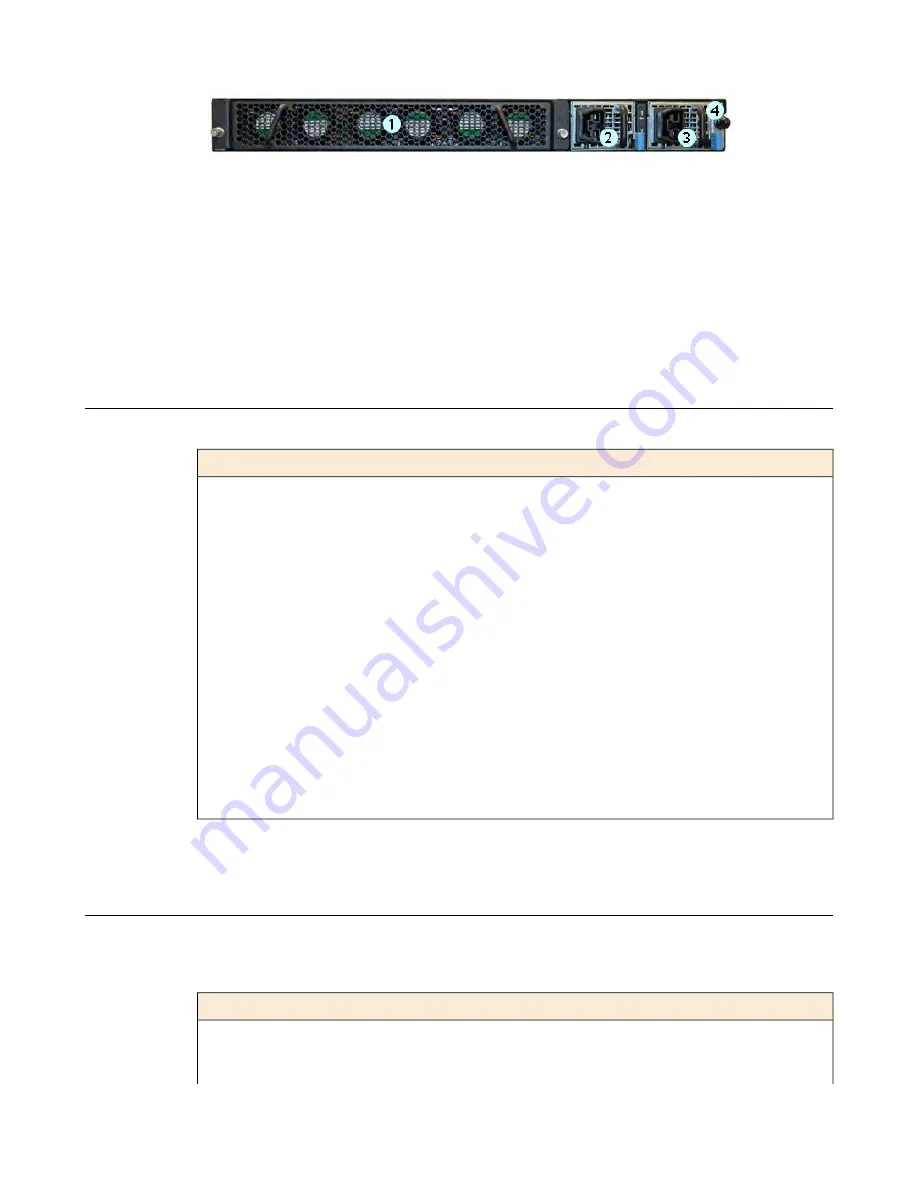
Figure 10: Back view of the i7000/i10000 Series High Voltage DC-powered platform

1.

Fan tray (removable)

2.

Power input panel 1 (DC power receptacle)

3.

Power input panel 2 (DC power receptacle)

4.

Chassis ground terminal

Hardware included with the platform

This platform includes all of the hardware components listed here.

Hardware

Quantity

Power cables (black), AC power only, per platform configuration. Might include multiple
power cable types if product is delivered outside of the US/Canada. By default, these platforms
include one power supply and power cable: i5000 Series.

1 or 2

Power cables (black), AC power only, per platform configuration. Might include multiple
power cable types if product is delivered outside of the US/Canada.

2

DC ring terminals, standard DC power only. By default, this platform includes two DC power
supplies and four ring terminals.

4

RJ45 to RJ45 failover cable, CAT 5 crossover (blue)

1

RJ45 to DB9 console port cable (beige)

1

RJ45F to RJ45M rolled adapter (beige)

1

Quick-install rail kit

1

Rail lock brackets

2

M3 x 8mm flathead screws, black with patch

4

#8-32 pan head screws, steel zinc

4

Peripheral hardware required

For each platform, you might need to provide additional peripheral hardware. If you plan to remotely
administer the system, it would be helpful to have a workstation already connected to the same subnet as
the management interface.

Description

Type of hardware

You must provide networking devices that are compatible with the
network interface ports on the platform. You can use either
1000/10000-Megabit or 40-Gigabit Ethernet switches.

Network hubs, switches, or
connectors to connect to the
platform network interfaces

8

Platform Overview

Содержание i5000 Series

Страница 1: ...Setting Up the i5000 i7000 i10000 i11000 Series Platform MAN 0620 08...

Страница 2: ......

Страница 3: ...l the rail lock brackets 12 About grounding the platform 13 Connect the ground lug to the ground terminal 14 Connect the cables and other hardware 14 Configure a management IP address using the LCD 15...

Страница 4: ...4 Table of Contents...

Страница 5: ...0031 xx The i10000 Series includes the i10010 platform which includes a configuration with 100GbE and 40GbE network connectivity i10810 and i10610 Note Verify the part number of your platform by typin...

Страница 6: ...5 10GbE SFP ports 8 6 40GbE QSFP ports 46 7 Indicator LEDs 8 2 2 inch LCD touchscreen Figure 5 Front view of the i10010 platform 1 10 100 1000 BaseT capable management port 2 Hi Speed USB port 3 Cons...

Страница 7: ...two power supplies a chassis ground terminal and the storage drives located behind the fan tray Figure 8 Back view of the i7000 i10000 i11000 Series AC powered platform 1 Fan tray removable 2 Power i...

Страница 8: ...terminals standard DC power only By default this platform includes two DC power supplies and four ring terminals 4 RJ45 to RJ45 failover cable CAT 5 crossover blue 1 RJ45 to DB9 console port cable bei...

Страница 9: ...ugh the console port Important In the event that network access is impaired or not yet configured the serial console might be the only way to access the unit Serial console You should perform all inst...

Страница 10: ......

Страница 11: ...o repackage and ship the platform later About the quick install rails The quick install rails are optimized for installation into square hole cabinets but can be installed in other cabinet styles such...

Страница 12: ...rail lock brackets to each side of the unit using two of the black M3 x 8mm flathead screws that are provided with the kit Use 5 inch pounds 0 6 Newton meters of torque on these screws 2 Slide the uni...

Страница 13: ...vice or installation procedures You can connect other bonding or grounding conductors to a grounding connector provided a reliable bond between the connector and the equipment is not disturbed during...

Страница 14: ...s using the serial console as these procedures require reboots in which network connectivity is lost temporarily 1 If you are using the default network configured on the management interface connect a...

Страница 15: ...rial failover cable to the FAILOVER port on each unit For more information about configuring failover see BIG IP Device Service Clustering Administration at support f5 com You can now assign a managem...

Страница 16: ...ch the screen to activate the LCD menus 3 Tap Setup The Setup screen displays 4 Tap Management The Management screen displays 5 For the Type setting tap to select either IPv4 or IPv6 6 If you are usin...

Страница 17: ...DHCP option is set to OFF If the DHCP option was set to ON tap OFF and then tap Commit to save the change c Tap Back to return to the Management screen If you selected IPv4 this screen displays If yo...

Страница 18: ...gured License the platform Once the management IP address is configured for the platform you can use the Configuration utility to license the appropriate F5 software 1 Using a Web browser navigate to...

Страница 19: ...he first screen you see is the Introduction screen 3 Click Next to view the License screen 4 Follow the instructions in the Configuration utility to license the platform For more information about lic...

Страница 20: ......

Страница 21: ...n damage Do not plug the unit into a branch circuit shared by more electronic equipment than the circuit is designed to manage safely at one time Route and secure power cords so that they do not obstr...

Страница 22: ...Figure 14 Rack mounting spatial requirements for the i5000 i7000 i10000 i11000 Series platform 22 Environmental Guidelines...

Страница 23: ...ase part number printed on the label on top of the individual power supply Note The full part number is a nine digit number PWR XXXX YY The base part number is seven digits and must match but the suff...

Страница 24: ...eck whether or not the socket outlet from which the equipment is to be powered provides a connection to the building protective earth If not the SERVICE PERSON shall arrange for the installation of a...

Страница 25: ...o understand the unit s airflow direction so that you can ensure proper cooling The platform employs a negative pressure fan system which draws cold air in from the front of the chassis Figure 17 Airf...

Страница 26: ......

Страница 27: ...arning This is a Class A product In a domestic environment this product may cause radio interference in which case the user may be required to take adequate measures FCC Compliance This equipment has...

Страница 28: ...ndards applicable to Information Technology products at the time of manufacture VCCI Class A Compliance This is a Class A product In a domestic environment this product may cause radio interference in...

Страница 29: ...connecting to ground terminal 14 locating 13 location 5 guidelines battery replacement 21 H hardware AC powered equipment 24 DC powered equipment 24 hardware requirements for peripherals 8 hard wired...

Страница 30: ...l requirements for 21 rail lock brackets installing 12 rail mount installing rail lock brackets 12 redundancy for system 14 redundant system configuration 14 See also device service clustering DSC rem...

Отзывы:

Похожие инструкции для i5000 Series