1
.
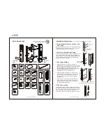
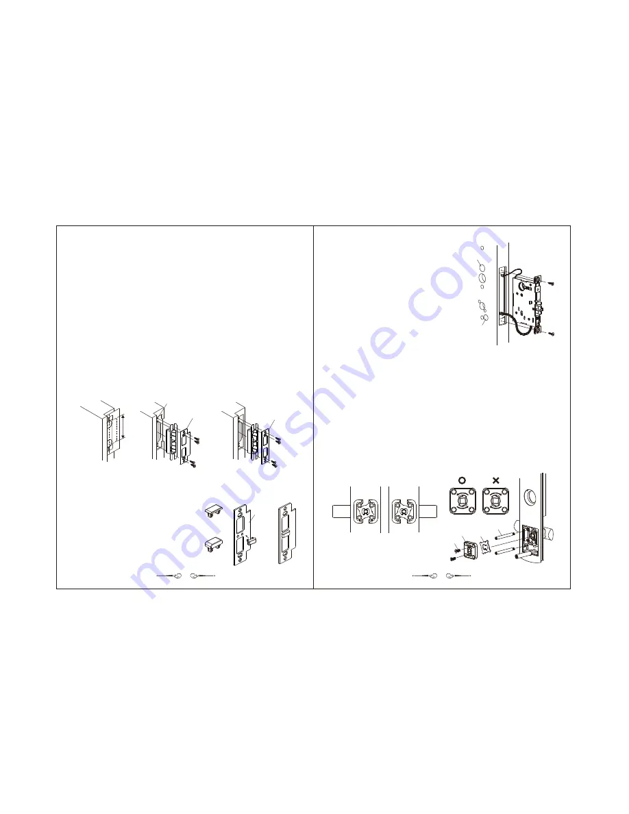
Swing the door almost closed up to the door jamb and draw the latch center line on the
door jamb to match the latch center line on the door.
2. Place the strike paper template onto the door jamb, aligning it to the latch center line,
and mark the centers of the holes on the door jamb as specified by the paper template.
Following the markings, drill 2 holes, 1" (25.4mm) in diameter and 1-1/8" (29mm)deep, on
the door jamb and then chisel out a rectangular groove (the line segments of the strike
paper template) 1" (25.4mm) in width, 3-5/16" (84mm) in height and 1-1/8" (29mm) deep
based on the positions of the 2 holes.
3
.
At the position specified by the paper template, cut a groove 1-5/16" (33mm) in width,
4-7/8" (124mm) in height and 5/32" (4mm) deep on the door jamb to provide a level
surface on the door jamb once the strike is installed.
4
.
Finally, following the markings, drill 2 guiding holes, 1/8" (3mm) in diameter and 19/32"
(15mm) deep, to fasten the strike with strike screws
(for a metal door, metal screws can be used to fasten the strike)
.
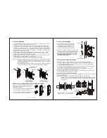
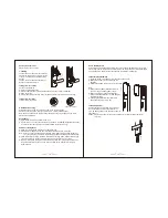
Caution : 1. Doors with a thickness greater or less than 55mm use strike plates of different
specifications (as illustrated below). Please chisel out the groove for the strike
plate as appropriate according to the strike specifications and by referring to the
paper template markings.
2. The strike provided by the manufacturer must be used to prevent a malfunction
of automatic locking as a result of the security latch's inability to depress.
3
4
3-5/16"
(84mm)
If the door slot thicker than 45mm, please install
into strike to prevent to
malfunction of lock case.
1. If the door slot with a thickness within 45-75mm,
please install strike liner thickness 20mm.
2. If the door slot with a thickness within 75-105mm,
please install strike liner thickness 50mm.
Reinforcement Plate
Optional Accessories (
/Special Strike)
Reinforcement Plate
(2mm)
(5mm)
Special
strike
Standard strike for a
door thinner than 55mm
Special strike for a
door thicker than 55mm
5.
Strike Installation
ø1/8" (ø3mm) guiding hole
19/32" (15mm) deep
Standard strike
Special strike
6.
Lock Case Installation
1
.
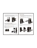
First, insert the upper and lower IC wires
into the door's groove and then pull them
out through the penetrating holes above
and below the groove on the room side
(do not cross the upper and lower cables).
2
.
Insert the
into the groove, gently pulling
the
at the same time without breaking them,
and then position the reinforce plate as illustrated,
fastening the latch tightly with lock case screws
(for a metal door, metal screws can be used
instead to fasten the latch)
.
lock case
wires
Lower wire
exit hole
The room side
Upper wire exit hole
7. Exterior Lock Body Installation
1
.
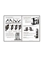
Screw the 2 screw posts into the opposite screw holes on the exterior lock body
according to the door handing : for a right-hand door, screw posts are assembled in the
upper-left and lower-right corners, and for a left-hand door, screw posts are assembled
in the upper-right and lower-left corners.
2
.
Keep the lever level as illustrated, and then direct the protruded corners of the
to the trough of the lever axis, placing the
in the lever axis.
At this point, the protruded corner will lean on the upper-right support for a right-hand
door and the upper-left support for a left-hand door.
3
.
Place the rotating plate onto the screw posts with the arrow above the square hole of the
direction changer pointing to the end of the lever.
4
.
Fasten the 2 rotating plate screws as illustrated.
5
.
Place the spring in the square hole of the rotating plate and then insert the exterior spindle into
the lever as illustrated.
Caution : Please rotate the lever downward to check whether it functions normally.
If the lever cannot be rotated downward, this indicates that the rotating plate is in the
wrong direction. To correct this, simply take off the rotating plate and rotate it before
re-inserting it.
fixing plate
fixing plate
Direction of the fixing
plate for right-hand door
Direction of the fixing
plate for left-hand door
Fixing screw
Rotating Plate
Screw post
Fixing plate


