


StudioStation 100 • Remote Communication and Control
72
Ethernet (LAN) Port
The rear panel LAN connector on the device can be connected to an Ethernet LAN or
WAN. Communication between the device and the control system or PC is via Telnet (a TCP
socket using port 23). The Telnet port can be changed, if necessary, via SIS or using the
StudioStation 100 user interface. This connection makes SIS control of the device possible
using a control system or PC connected to the same LAN or WAN. The SIS commands and
behavior of the product are common to the commands and behavior the product exhibits
when communicating by serial port or USB.
LAN port defaults:
DHCP:
off
StudioStation 100 IP address:
192
.
168
.
254
.
253
Subnet mask:
255
.
255
.
0
.
0
Gateway IP address:
0
.
0
.
0
.
0
Ethernet Connection
The Ethernet cable can be terminated as a straight‑through cable or a crossover cable and
must be properly terminated for your application.
•
Crossover cable
— Direct connection between the computer and StudioStation 100.
•
Patch (straight) cable
— Connection of the StudioStation 100 to an Ethernet LAN.
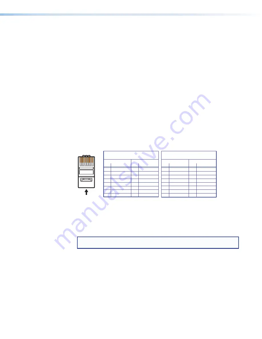
1 2 3 4 5 6 7 8
RJ-45
Connector
Insert Twisted
Pair Wires
Pins:
A cable that is wired as TIA/EIA T568A at one
end and T568B at the other (Tx and Rx pairs
reversed) is a "crossover" cable.
A cable wired the same at both ends is called
a "straight-through" cable because no pin/pair
assignments are swapped.
T568B
T568A
T568B
T568B
Straight-through Cable
(for connection to a switch, hub, or router)
End 1
End 2
Pin
Wire Color
Pin Wire Color
1
white-orange
1
white-orange
2
orange
2
orange
3
white-green
3
white-green
4
blue
4
blue
5
white-blue
5
white-blue
6
green
6
green
7
white-brown
7
white-brown
8
brown
8
brown
Crossover Cable
(for direct connection to a PC)
End 1
End 2
Pin
Wire Color
Pin Wire Color
1
white-orange
1
white-green
2
orange
2
green
3
white-green
3
white-orange
4
blue
4
blue
5
white-blue
5
white-blue
6
green
6
orange
7
white-brown
7
white-brown
8
brown
8
brown
Figure 68.
RJ-45 Ethernet Connector Pin Assignments
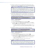
To establish a network connection to the StudioStation 100:
1.
Open a TCP socket to port 23 using the StudioStation 100 IP address.
NOTE:
If the local system administrators have not changed the value, the
factory‑specified default,
192
.
168
.
254
.
253
, is the correct value for this field.
The StudioStation 100 responds with a copyright message including the name of the
product, firmware version, part number, and the current date and time.
•
If the StudioStation 100 is not password‑protected, the device is ready to accept
SIS commands immediately after it sends the copyright message.
•
If the StudioStation 100 is password‑protected, a
Password
prompt appears below
the copyright message. Proceed to step 3.
2.
If the device is password protected, enter the appropriate administrator or user
password.
•
If the password is accepted, the device responds with
Login
User
or
Login
Administrator
.
•
If the password is not accepted, the
Password
prompt reappears.
figure 68


