


Setup Guide — RGB 580xi
This guide provides basic instructions for an experienced
installer to set up and operate the Extron RGB 580xi.
Installation
Refer to the RGB 580xi User’s Manual for details.
C
Installation and service must be performed by authorized personnel only.
Step 1 — Powering down
Turn off or disconnect all equipment from power sources.
Step 2 — Mounting
Mount the interface as desired.
Step 3 — Video input
Connect an RGBHV, RGBS, RGsB, or RsGsBs analog video input to the
front panel 15-pin HD input connector. The pinout table is shown below.
Pin
Description
Wire ID
Pin
Description
Wire ID
15-pin HD male pinout table
1 red signal red coax
2 green signal green coax
3 blue signal blue coax
4 horizontal shift + green wire
5 horizontal shift
—
brown wire
6 red coax ground red coax shield
7 green coax ground green coax shield
8 blue coax ground blue coax shield
9 LED red orange wire
10 horizontal sync ground black coax shield
10 vertical sync ground yellow coax shield
10 audio ground black wire
10 LED ground yellow wire
10 shift ground grey wire
11 audio right red wire
12 audio left white wire
13 horizontal sync black coax
14 vertical sync yellow coax
15 LED green pink wire
Step 4 — Audio input
Connect an unbalanced stereo input to the front panel 3.5 mm stereo mini
jack.
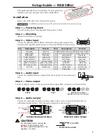
Step 5 — Video output
Connect a display device to the rear panel video output BNC connectors, as shown below.
RGBS
RGBHV
RGsB (Sync on Green)
RsGsBs
(output only if input is RsGsBs)
R
G
B
H/HV
V
R
G
B
H/HV
V
R
G
B
H/HV
V
Step 6 — Audio output
Connect an audio device to the 3.5 mm, 5-pole captive screw connector for balanced or
unbalanced audio output. Wire the male connector as shown here.
CAUTION
For unbalanced audio, connect the
sleeve(s) to the ground contact.
DO NOT
connect the sleeve(s) to the
negative (-) contacts.
Do not tin the wires!
Tip
NO Ground Here
Sleeve(s)
NO Ground Here
Tip
L
R
Balanced Audio Output
Unbalanced Audio Output
Tip
Ring
Tip
Ring
L
R
Sleeve(s)
1
15-pin HD Male Pin Locations
5
1
15
11
6
10
Sleeve ( )
Ring (R)
Tip (L)