background image

Quantum Ultra Series Videowall Processing Systems • Operation

60

2. 

On the 

Reset


Device

 window, select the radio button for the type of reset desired:

• 

Reset


Device


Settings


(Retain


TCP/IP


Settings


and


Image


Files)

 — 

Resets the Quantum Ultra to its factory default settings while keeping the IP 
addresses and other settings that have been entered, plus any image files that 
have been uploaded. This is the default.

• 

Reset


Device


Settings


and


Delete


All


Files


(Retain


TCP/IP


Settings)

 — Resets the unit to factory defaults and keeps IP address 

information. All uploaded image files are deleted and the default image files are 
restored. This is the “absolute system reset.”

• 

Reset


All


Settings


and


Delete


All


Files

 — Resets the unit to factory 

defaults. All user-uploaded image files are deleted, IP settings are reset to default, 
and the default image files are restored. 

NOTE:

  The factory configured passwords for all accounts on this device have 

been set to the device serial number. In the event of an absolute system 
reset, the passwords convert to the default, which is 

extron

.

3. 

Click the 

Reset

 button (see 

figure 61

1

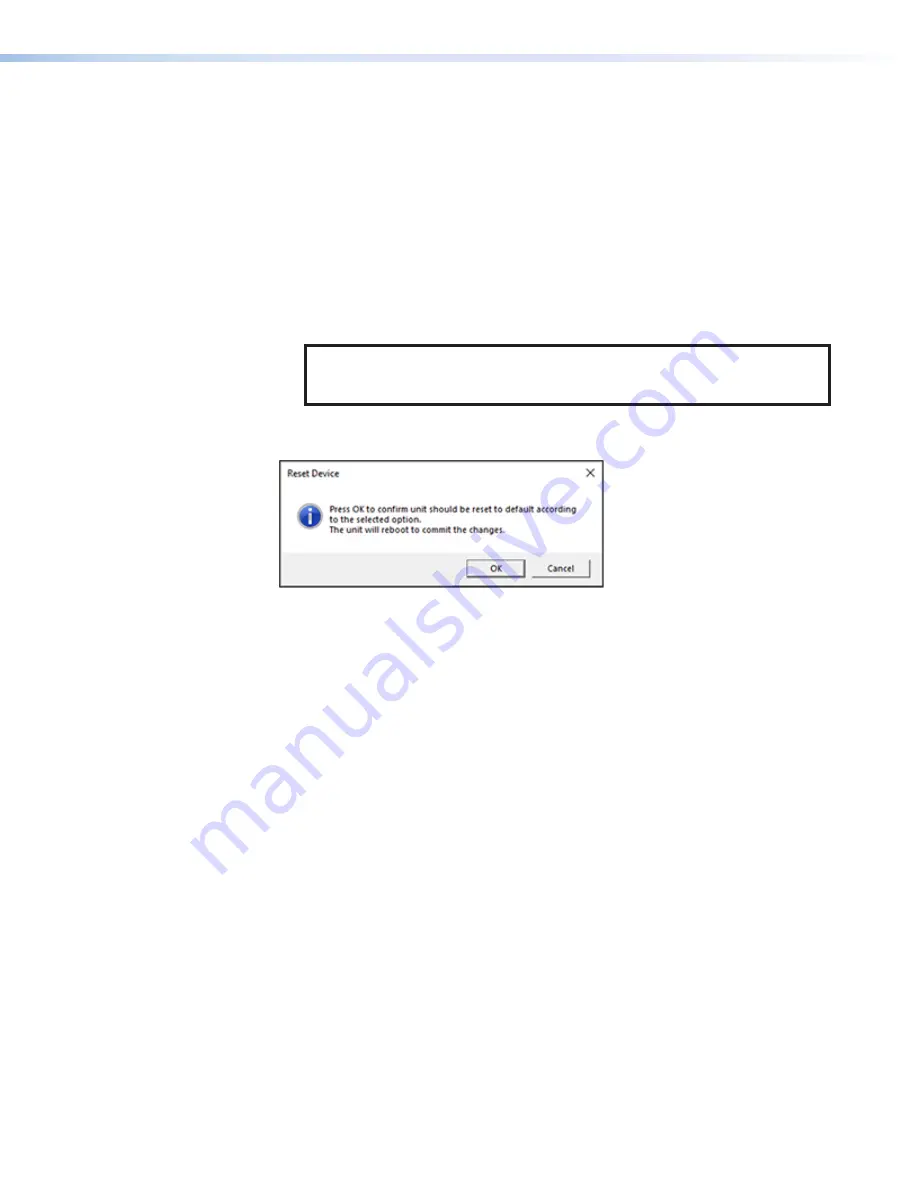
 on the previous page). The following 

prompt appears:

Figure 62. 

Reset Confirmation Prompt

4. 

Click 

OK

. The unit reboots and resets.

Service Mode

In service mode, you can access the Quantum Ultra Series 

C:

 and 

D:

 drives as well as the 

operating system Control Panel. To enter service mode:

1. 

On the Quantum Ultra 

Control


Panel

 main window, click 

Service


Mode

 (see 

figure 47

6

 on page 51). A prompt window opens with the following message: 

Write


protection


is


enabled


and


changes


will


not


be


saved


after


device 

is


rebooted


or


power


cycled.

The


device


must


restart


to


allow


changes


to


be


made.

Do


you


want


to


restart


now


to


make


changes


or


view


settings


only?

2. 

To enter service mode and change settings, click the 

Restart

 button on the prompt 

to reboot the unit and disable write protection, 

or

Click 

View


Only

 to view the current settings without making any changes to them. 

The unit displays the settings, but does 

not

 disable write protection. 

3. 

Follow the directions on any subsequent screens.

62 


Содержание Quantum Ultra Series

Страница 1: ...User Guide Quantum Ultra Series Videowall Processors Videowall Processing Systems 68 2760 01 Rev H 01 22 ...

Страница 2: ......

Страница 3: ...PoleVault PowerCage PURE3 Quantum ShareLink Show Me SoundField SpeedMount SpeedSwitch StudioStation System INTEGRATOR TeamWork TouchLink V Lock VN Matrix VoiceLift WallVault WindoWall XPA XTP XTP Systems and ZipClip Registered Service Mark SM S3 Service Support Solutions Trademarks AAP AFL Accu RATE Frame Lock ADSP Advanced Digital Sync Processing AVEdge CableCover CDRS Class D Ripple Suppression ...

Страница 4: ...adées fonctionne avec les câbles paires torsadées blindées UTP ou non blindées STP Afin de s assurer de la compatibilité entre FCC Classe A et CE les câbles STP et les connecteurs STP sont nécessaires NOTES This unit was tested with shielded I O cables on the peripheral devices Shielded cables must be used to ensure compliance with FCC emissions limits For more information on safety guidelines reg...

Страница 5: ...d examples of computer or device responses used in this guide the character 0 is the number zero and O is the capital letter o Computer responses and directory paths that do not have variables are written in the font shown here Reply from 208 132 180 48 bytes 32 times 2ms TTL 32 C Program Files Extron Variables are written in slanted form as shown here ping xxx xxx xxx xxx t SOH R Data STX Command...

Страница 6: ......

Страница 7: ...TP Outputs Only 43 Ethernet to RS 232 Insertion 43 Captive Screw Signal Insertion 44 Selecting the Insertion Method and RS 232 Protocol 45 Expansion Cards 46 Expansion Card Locations 47 Connecting the Expansion Cards 48 Operation 49 Starting the Control Panel 49 Buttons on the Control Panel 51 Loading Image Files 51 Updating the Password 53 Updating Firmware 54 Downloading a Firmware File 54 Uploa...

Страница 8: ... Fan Quantum Ultra 610 Only 102 Replacing a Disk Drive Quantum Ultra and Ultra II 610 106 Replacing the System Board Computer SBC Assembly Quantum Ultra 610 and Ultra II 610 109 Removing the SBC Assembly 109 Installing a New SBC Assembly 111 Reference 112 Best Practices for Cleaning Your Extron Products 112 Cleaning Fiber Optic Connectors and Cables 113 Mounting the Quantum Ultra Series 114 UL Gui...

Страница 9: ...a refers to only the Quantum Ultra 610 and 305 Quantum Ultra II refers to only the Quantum Ultra II 610 and 305 Quantum Ultra Connect refers to only the Quantum Ultra Connect 128 or 84 About the Quantum Ultra Series Videowall Processors The Extron Quantum Ultra Series Videowall Processors are modular 4K video processors that support ultra high resolutions up to 2560x1600 and 4096x2160 4K 60 Hz on ...

Страница 10: ...ne bus of the other models IEC C20 power connectors on the rear panel instead of the standard IEC connectors of the Quantum Ultra 610 Quantum Ultra II 610 only 1500 watt primary and redundant power supplies with non user replaceable internal fans Quantum Ultra II 610 only Quantum Ultra Connect 128 and 84 The Quantum Ultra Connect 128 and 84 have fixed configurations The Quantum Ultra Connect 128 h...

Страница 11: ...ty and information assurance testing for use in government applications and other mission critical environments Key Minder continuously verifies HDCP compliance for quick reliable switching Key Minder authenticates and maintains continuous HDCP encryption between input and output devices to ensure quick and reliable switching in professional AV environments while enabling simultaneous distribution...

Страница 12: ...itching between presets delivering fast glitch free and professional looking presentations for any application Solid state storage Ensures long term operation and fast boot times Write protected operating system Prevents any permanent modification to the file system without administrator password verification and eliminates the possibility of viruses or unauthorized file updates from being retaine...

Страница 13: ...tures logos and messages Alpha channel and transparency are also supported 6U 10 slot Card Frame The 6U 10 slot Quantum Ultra and Ultra II 610 card frames support any combination of input and output cards for I O sizes from 36x4 to 4x36 or anything in between 3U 5 slot Card Frame The 3U 5 slot Quantum Ultra and Ultra II 305 card frames support any combination of input and output cards for I O size...

Страница 14: ...nections IN SMD 100 card This allows decoding resources to be shared within the same subnet or split across multiple subnets providing increased flexibility when designing complex streaming networks Transmits up to four outputs at distances up to 330 feet 100 meters over a shielded CATx cable OUT4DTP card Reduces system complexity when output extension is required for driving videowall displays up...

Страница 15: ...effective 4K 60 HDMI videowall processors for videowalls with up to eight screens 400 Gbps HyperLane video bus delivers real time performance The Extron HyperLane video bus has a total throughput of 400 Gbps easily accommodating the high bandwidth demands of large videowalls displaying many simultaneous HD and 4K sources 3U 5 slot card frame IN4HDMI input card supports signals up to 4K 60 The IN4H...

Страница 16: ...sed down a 500 Gbps HyperLane bus Width Height Frame Rate Bandwidth Gbps Number of Native Sources 1024 768 60 1 42 318 1280 720 60 1 66 272 1920 1080 60 3 73 120 1920 1200 60 4 15 108 1600 1200 60 3 46 130 2560 1600 60 7 37 61 3840 2160 30 7 46 60 4096 2160 30 7 96 56 3840 2160 60 14 93 30 4096 2160 60 15 93 28 4096 2400 60 17 69 25 NOTE Bandwidth values do not include overhead data required for b...

Страница 17: ...USB 1 2 3 A B 100 240V A MAX 50 60 Hz POWER LAN SYSTEM REMOTE SLOT 5 SLOT 4 SLOT 2 SLOT 3 SLOT 1 DISCONNECT POWER CORD BEFORE SERVICING INPUTS QUANTUM IN4HDMI INPUTS QUANTUM IN4HDMI INPUTS QUANTUM IN4HDMI OUTPUTS QUANTUM OUT4HDMI OUTPUTS QUANTUM OUT4HDMI POWER 12V 1A MAX G Tx Rx RTS CTS COM 1 G Tx Rx COM 2 V C G VOL RELAYS 1 2 C 1 2 3 4 G DIGITAL I O PWR OUT 6W eBUS V S S G LAN IPCP PRO 250 IR S S...

Страница 18: ... 2 3 4 1 2 3 4 1 2 3 4 1 2 3 4 OUTPUTS 1 2 3 4 1 2 3 4 POWER 12V A MAX G Tx Rx RTS CTS COM 1 G Tx Rx COM 2 V C G VOL RELAYS 1 2 C 1 2 3 4 G DIGITAL I O PWR OUT 6W eBUS V S S G LAN IPCP PRO 250 IR S S G Extron Quantum Ultra 610 Ultra high Bandwidth 4K Videowall Processor 4K PC 4K Media Player Extron IPCP Pro 250 IP Link Control Processor Control LAN HDMI HDMI HDMI HDMI Ethernet Ethernet Ethernet Et...

Страница 19: ...GTx SIG LINK OUT SIG LINK OUT DTP OUT HDBT SIG LINK 4A MAX DTP POWER 12V OUT SIG LINK QUANTUM OUT4DTP OUT TxRx Rx GTx OUT TxRx Rx GTx TxRx Rx GTx TxRx Rx GTx SIG LINK OUT SIG LINK OUT DTP OUT HDBT SIG LINK 4A MAX DTP POWER 12V OUT SIG LINK QUANTUM OUT4DTP OUT TxRx Rx GTx OUT TxRx Rx GTx TxRx Rx GTx TxRx Rx GTx SIG LINK OUT SIG LINK OUT DTP Extron Quantum Ultra 610 Ultra high Bandwidth 4K Videowall...

Страница 20: ...DE MENU RES 480 480p 720p 1080i 1080p DIREC TV HD SELECT D I R E C T V PUSH PUSH POWER GUIDE MENU RES 480 480p 720p 1080i 1080p DIREC TV HD SELECT D I R E C T V PUSH PUSH POWER GUIDE MENU RES 480 480p 720p 1080i 1080p DIREC TV HD SELECT D I R E C T V PUSH PUSH POWER GUIDE MENU RES 480 480p 720p 1080i 1080p DIREC TV HD SELECT D I R E C T V PUSH PUSH POWER GUIDE MENU RES 480 480p 720p 1080i 1080p DI...

Страница 21: ...r from the processor and all other equipment in the system 2 If desired rack mount the unit see Mounting the Quantum Ultra Series on page 114 3 Connect HDMI sources and LAN connections to the installed input cards Connect HDMI displays DTP or HDBaseT receivers or an XTP matrix switcher to the connectors on the installed output cards as appropriate 4 Secure each HDMI connector with a provided LockI...

Страница 22: ...ter that is connected to the same network as the Quantum Ultra Series device to assign an IP address to the processor see the VCS Help File for instructions NOTE A gateway IP address is required on the PC running VCS for the Quantum Ultra Series to be detected The gateway IP address does not need to be valid or in the same subnet for the detection to work Internal operating system The Quantum Ultr...

Страница 23: ...or LED lights to indicate the following Green blinking The processor is booting Green steady The unit is ready for operation Amber steady The system is in power saving mode Red steady A fan has failed Quantum Ultra and Ultra II 610 Front Panel Door The front panel of the Quantum Ultra and Ultra II 610 has a door that opens to provide access to user replaceable parts This front panel door covers th...

Страница 24: ...OT 10 DISCONNECT POWER CORD BEFORE SERVICING 100 240V 5 0A MAX 50 60 Hz 100 240V 5 0A MAX 50 60 Hz POWER LAN SYSTEM REMOTE OUTPUTS SLOT 8 QUANTUM OUT4HDMI OUTPUTS SLOT 7 QUANTUM OUT4HDMI OUTPUTS SLOT 6 QUANTUM OUT4HDMI INPUTS SLOT 5 INPUTS SLOT 4 INPUTS SLOT 3 INPUTS SLOT 2 INPUTS SLOT 1 QUANTUM IN4HDMI QUANTUM IN4HDMI QUANTUM IN4HDMI QUANTUM IN4HDMI 1 2 3 4 1 2 3 4 1 2 3 4 1 2 3 4 1 2 3 4 1 2 3 4...

Страница 25: ...the secondary power supply to provide uninterrupted operation in the event of failure of the primary supply NOTES The Quantum Ultra II 610 model has IEC C20 power connectors shown at right while the Quantum Ultra and Quantum Ultra II 305 models have standard US IEC connectors The Quantum Ultra II 610 requires an IEC C19 power cord to connect AC power Temperature controlled fans run at 100 as a fai...

Страница 26: ...on systems the LAN A ports of all chassis in the system must be connected to the same network If desired LAN B ports of any of the chassis can be connected to a separate network for VNC or RSS sources I Input and output card slots Each of these slots supports either an input card or an output card depending on the configuration at least one input and output card must be installed NOTE The Quantum ...

Страница 27: ...d Output Cards The Quantum Ultra and Ultra II 610 chassis contain 10 slots for input and output cards while the Quantum Ultra 305 Quantum Ultra Connect 128 and Quantum Ultra Connect 84 each have five Quantum Ultra and Ultra II 610 and 305 Each card contains either Four HDMI or HDMI 4K PLUS input connectors Four HDMI or HDMI 4K PLUS output connectors Four DTP RJ 45 output connectors Two RJ 45 input...

Страница 28: ...cards of the same type HDMI HDMI 4K PLUS DTP or Expansion Out If installing cards yourself Do not intersperse Input cards with output cards Input cards of different types HDMI input cards HDMI 4K PLUS input cards and IN SMD 100 cards with each other or Output cards of different types HDMI output cards HDMI 4K PLUS output cards and DTP cards Install the cards in the chassis in the following order t...

Страница 29: ...ps 4K 60 Hz or 144 Gbps 8 x 4K 60 Hz for 4K PLUS cards Width Height Frame Rate Bandwidth Gbps Unique Instances on IN4HDMI and IN SMD 100 Cards Unique Instances on IN4HDMI 4K PLUS card 480 270 60 0 233 16 16 640 360 60 0 415 16 16 960 540 60 0 933 16 16 1280 720 60 1 659 10 16 1920 1080 60 3 732 4 16 2560 1600 60 7 373 2 16 3840 2160 30 7 465 2 16 3840 2160 60 14 930 1 8 Should more instances be re...

Страница 30: ...cation size per source Two unique minification sizes per source Four unique minification sizes per source Processed at 30 Hz Processed at 15 Hz 1 1 4 1 1 4 1 1 4 1 1 4 1 1 4 1 1 4 1 1 3 1 1 3 1 1 3 1 1 4 1 1 3 1 1 3 1 1 3 1 1 3 1 1 2 1 1 2 1 1 2 1 1 2 1 1 2 1 1 2 1 1 2 1 1 1 1 1 1 1 1 1 1 1 1 1 1 1 1 1 1 1 1 1 Figure 10 Example of Four Inputs at 1080p 60 Hz on One Input Card IN4HDMI or IN SMD 100 ...

Страница 31: ...e source Four unique minification sizes for one source Processed at 15 Hz Processed at 30 Hz 1 1 2 1 1 2 1 1 2 1 1 2 1 1 2 1 1 2 Figure 13 Example of One 4K Input at 4K 30 Hz on One Input Card Example 5 One 4K input at 60 Hz column or quad format applied to one input card One unique minification size for one 4K grouped source Two unique minification sizes for one 4K grouped source Four unique mini...

Страница 32: ...at 60 Hz or two 4096x2160 signals at 30 Hz The HDMI 4K PLUS input cards have the same number and type of connectors with the addition of support for resolutions of 4096x2160 60 Hz on all four inputs including audio which can be embedded onto outputs on an OUT4HDMI 4K PLUS card They are supported on Quantum Ultra II models only INPUTS QUANTUM IN4HDMI 1 2 3 4 Figure 15 HDMI Input Card NOTE Figure 15...

Страница 33: ...DCP authorization disabled protected material is not passed Each input can be set to enable or disable the support of HDCP signals If HDCP authorization is disabled the input does not negotiate with the source device and forces the source to transmit only unencrypted video Input rotation Sources that have their content pre rotated can be rotated within the Quantum Ultra Series processor to be disp...

Страница 34: ...otated 1080p sources can be shown at 15 Hz Processed at 15 Hz Processed at 30 Hz Processed at 60 Hz 1 1 1 1 1 1 1 1 1 1 1 1 1 1 2 1 1 2 1 1 2 1 1 2 1 1 3 1 1 3 1 1 3 1 1 3 1 1 4 1 1 4 1 1 4 1 1 4 Figure 17 Example of Four Rotated 1080p Inputs 60 Hz on One Input Card Example 2 One rotated 1080p input at 60 Hz applied to one input card Two unique minification sizes for one source Four unique minific...

Страница 35: ...ed at 30 Hz 1 1 2 1 1 2 1 1 2 Figure 20 Example of One Rotated 4K Input 30 Hz on One Input Card Maximum instances of a rotated source per input card IN4HDMI 4K PLUS The following examples show the maximum number of instances of a single source that can be provided by one HDMI 4K PLUS input card at different resolutions and refresh rates Example 1 Four rotated 4K inputs at 60 Hz applied to one inpu...

Страница 36: ...w the current EDID that has been set for each input If no project file has been saved on the Quantum Ultra the default EDID setting of 1080p 60 Hz is applied see the VCS Help File provided with the software for details on selecting and monitoring EDID IP inputs Quantum Ultra and Ultra II 610 and 305 Only The IN SMD 100 cards each contain two identical RJ 45 connectors LAN A and LAN B Connect these...

Страница 37: ...input card supports the following streaming methods provided by the Extron SME 100 Extron SMP 351 and 3rd party encoders UDP TS Push Single program MPEG 2 Transport stream SPTS multicast only RTP Push Native elementary video streams multicast only Single program MPEG 2 Transport stream SPTS RTP TS multicast only RTP RTSP unicast or multicast Pull RTP and RTSP interleaved over a UDP connection Unic...

Страница 38: ...information SDP Session Description Protocol RFC 4145 and 4566 Allows RTSP initialization of the Quantum Ultra IP card using a locally stored SDP file to function as a browser helper application In practice the IP card may use the DESCRIBE method to initialize RTSP Also used to encapsulate the data for SAP Transport layer protocols UDP User Datagram Protocol For multicast and possible control and ...

Страница 39: ...dard HDMI output card The HDMI 4K PLUS output card appears the same except for the card name OUT4HDMI 4K PLUS in the upper right corner of its front panel HDMI 4K PLUS output cards Quantum Ultra II models only Like the standard HDMI output cards these cards have four female HDMI A connectors numbered 1 through 4 from left to right to which up to four HDMI or DVI with an appropriate adapter display...

Страница 40: ...T sink devices via the OVER TP control connectors 3 Remote power is not supported 3 OVER TP control connectors Each DTP output connector has an RS 232 and IR control connector associated with it Connect serial RS 232 signals modulated IR signals or both to these 3 5 mm 5 pole captive screw connectors the ground pin is shared to insert bidirectional RS 232 and IR communications including SIS comman...

Страница 41: ...port for 4K at 30 Hz and 2560x1600 at 60 Hz A possible configuration might consist of a single channel greater than 165 MHz plus two channels that are less than 165 MHz as shown in figure 25 In this example output 2 is configured to support up to 4K at 30 Hz and outputs 3 and 4 are configured to support up to 1920x1200 at 60 Hz OUTPUTS QUANTUM OUT4HDMI Disabled 300 MHz 165 MHz 165 MHz 1 2 3 4 Figu...

Страница 42: ...0 X 2048x1536 X 2560x1080 X 2560x1440 X 2560x1600 X 3840x2160 X X X X X X X 3840x2400 X X 4096x2160 X X X X X X X 3840x2160 C X X X X X X X X 4096x2160 C X X X X X X X X 3840x2160 Q X X X X X X X X 3840x2400 Q X 4096x2160 Q X X X X X X X X 4096x2400 Q X Custom rate 1 10 Default resolution and refresh rate Not supported on OUT4HDMI and OUT4DTP card connectors 1 and 3 Supported on OUT4HDMI 4K PLUS c...

Страница 43: ...adjusted in order to be supported by the HyperLane bus Contact an Extron representative for assistance Output grouping and canvases The VCS program provides screen workspaces called canvases or output groups on which to design the videowall Figure 26 Canvas Example A canvas contains a grid diagram in which each cell shows the following information about a display on the videowall 1 1 1 2 2 2 3 3 3...

Страница 44: ...window presets see the VCS Help File included with VCS to set up these presets Multiple canvases Quantum Ultra and Ultra II 610 and 305 Only For a Quantum Ultra or Ultra II 610 or 305 the videowall project can contain up to 10 canvases Each canvas can contain connectors on any output board on any chassis and multiple canvases can be defined on a single output card Canvas 2 1080p Rotated 90 Canvas ...

Страница 45: ...h this selection an HDMI sink device format is determined by the detection of a valid CEA extension header in the second block of EDID data HDCP mode Using VCS you can select the HDCP mode which specifies whether the Quantum Ultra Series processor encrypts source content The processor can be set to always encrypt HDMI data to never encrypt Off option or to not encrypt after attempting unsuccessful...

Страница 46: ... Example 1 All source windows on one output channel In this example 64 windows have been assigned to output channel connector 1 1 No additional windows are available for output channels 1 1 2 1 1 3 and 1 1 4 Additional windows can be assigned to other cards 1 8 64 Output Channel 1 1 1 Windows 1 through 64 all available windows Figure 31 Example of All Available Windows Assigned to One Output Chann...

Страница 47: ...mat standard column or quad Example 1 Four 1080p outputs at 60 Hz Example 2 Two 4K outputs at 30 Hz channels 1 and 3 disabled Example 3 Two 4K column outputs at 30 Hz Example 4 One 4K column output at 60 Hz channels 1 and 3 disabled Example 5 One 4K quad output at 60 Hz 1 10 1 1 10 2 1 10 2 1 10 2 1 10 2 1 10 2 1 10 1 1 10 1 1 10 3 1 10 3 1 10 3 1 10 4 1 10 4 1 10 4 1 10 4 1 10 4 Figure 33 Maximum...

Страница 48: ... processor can be rotated to support the rotated displays In contrast to input rotation which rotates the source content within a window output rotation affects the entire output signal which includes all sources window text images and HDCP messaging Figure 35 Output Rotation The Quantum Ultra Series standard HDMI output cards can support rotation of two 1920x1080 outputs at 60 Hz or one 3840x2160...

Страница 49: ...djustments Edge blending compensation Quantum Ultra and Ultra II 610 and 305 only In certain situations it may be desirable to create an overlap of video between adjacent displays This overlap melds the two images from two separate outputs into a single image and prevents a visible separation line between the two images Use VCS to set or adjust the amount of horizontal and vertical overlap of the ...

Страница 50: ...o let you control the Quantum Ultra and to set up videowall applications via the computer You must use VCS to set up the Quantum Ultra Series chassis However you can use SIS to reset the IP address of LAN port A from the default 192 168 254 254 without interacting directly with the embedded operating system interface LAN port B is not accessible via SIS but can be configured via VCS or the embedde...

Страница 51: ...S 232 insertion port number is entered as the Telnet port number when you establish communication with the insertion port The port numbers are automatically assigned to the DTP outputs and are numbered sequentially starting with 2001 Captive screw insertion A control signal applied to an RS 232 captive screw port is tied directly to the associated TP port You must physically connect a cable attach...

Страница 52: ...G Tx Rx G Tx Rx G Tx Rx G Tx Rx G RTSCTS S G S G S G S G 5 6 7 8 5 6 7 8 SWITCHED 12 VDC 40W MAX TOTAL 3 4 COM eBUS FLEX I O RELAYS IR SERIAL 12 VDC AV LAN LAN Control Processor DTP HDMI 330 Rx OVER DTP RS 232 IR Tx Rx Tx Rx G L R POWER 12V 0 7A MAX AUDIO SIG LINK DTP IN OUTPUTS AV LAN Figure 38 Typical Ethernet to RS 232 Insertion to an Output Endpoint Captive Screw Signal Insertion Figure 39 on ...

Страница 53: ... 2 3 7 5 6 8 S G S G S G S G Tx Rx G Tx Rx G Tx Rx G Tx Rx G RTSCTS 1 2 1 2 3 4 1 2 3 4 3 2 1 4 G Tx Rx G Tx Rx G Tx Rx G Tx Rx G RTSCTS S G S G S G S G 5 6 7 8 5 6 7 8 SWITCHED 12 VDC 40W MAX TOTAL 3 4 COM eBUS FLEX I O RELAYS IR SERIAL 12 VDC AV LAN LAN RS 232 or IR Insertion Quantum Ultra Control Processor OUTPUTS OUTPUTS DTP HDMI 330 Rx RS 232 or IR Rear Panel Front Panel DTP HDMI 330 Rx OVER ...

Страница 54: ... be linked using four pairs of expansion cards System Size Maximum Inputs and Outputs 1 processor 40 2 processors 72 3 processors 104 4 processors 136 5 processors 168 All chassis in an expansion system are connected to the same network via their LAN A ports The first primary chassis in the signal chain is always a Quantum Ultra 610 and controls the other secondary chassis in the chain The last un...

Страница 55: ...ard is installed in the last slot slot 10 of the primary chassis to enable connection to the secondary chassis 2 On the secondary chassis The Expansion IN card is installed in the first slot slot 1 to accept the connection from the Expansion OUT card in the previous chassis see figure 43 1 SLOT 9 SLOT 10 SLOT 8 SLOT 7 SLOT 6 SLOT 5 SLOT 4 SLOT 3 SLOT 2 SLOT 1 QUANTUM EXPANSION IN INPUTS A C B OUTP...

Страница 56: ... TxRx Rx GTx SIG LINK OUT 1 OVER TP HDBT 4A MAX DTP POWER 12V OUTPUTS QUANTUM OUT4DTP TxRx Rx GTx SIG LINK OUT 4 DTP OVER TP TxRx Rx GTx SIG LINK OUT 3 OVER TP TxRx Rx GTx SIG LINK OUT 2 OVER TP TxRx Rx GTx SIG LINK OUT 1 OVER TP QUANTUM ULTRA 610 Tx Rx G CONFIG RS 232 A B SLOT 9 SLOT 10 DISCONNECT POWER CORD BEFORE SERVICING 100 240V A MAX 50 60 Hz 100 240V A MAX 50 60 Hz POWER LAN SYSTEM REMOTE ...

Страница 57: ...Write Protection Shutting Down the Device Starting the Control Panel To access the Quantum Ultra Series Control Panel 1 Connect a USB keyboard and mouse to the USB system connectors on the rear panel see figure 45 You can also connect a USB flash drive to a USB system connector to load and manage picture files or upload new firmware SYSTEM USB Ports for Keyboard Mouse or Flash Drive HDMI Out Port ...

Страница 58: ...a Control Panel Main Window 4 The Quantum Ultra Control Panel window contains eight buttons that let you access the setup and management tasks for the Quantum Ultra see figure 46 6 Click one of these buttons to proceed to the desired task see Buttons on the Control Panel on page 51 The Control Panel window also contains the following status panels that enable you to observe status and activity of ...

Страница 59: ...Settings window from which you can view or modify the IP addresses of the LAN A and LAN B ports see Modifying Network Settings from the Control Panel on page 58 Reset Device 5 Enables you to reset the Quantum Ultra to different levels of the default state see Resetting the Device from the Control Panel on page 59 Service Mode 6 Provides access to the file system and a shortcut to the operating sys...

Страница 60: ...fferent drive Figure 48 USB Flash Drive Containing Picture Files 4 On the USB drive locate the image files to be loaded to the Quantum Ultra Series device and drag or copy them to the Pictures folder on the unit D Data drive Figure 49 Copying Two Picture Files to the Quantum Ultra Series Device Data Drive The files can now be accessed via VCS for use in configuration see the VCS Help File for more...

Страница 61: ...proceeding with the next step 2 On the Change Password window enter in the appropriate fields The current password the default password is extron The new password The new password again to confirm it Figure 50 Change Password Fields 3 Click the Enter button at the bottom of the Change Password window The following prompt opens informing you that the unit will reboot and enable write protection for...

Страница 62: ...ad it to the unit Downloading a Firmware File 1 On the Extron website hover the mouse pointer over the Download tab see figure 52 1 then click the Firmware link 2 in the Downloads column i t Figure 52 Downloading Firmware 2 On the Download Center screen click the Q link see figure 53 1 3 Scroll to locate the Quantum Ultra firmware and click the Download link at the far right 2 Figure 53 Download C...

Страница 63: ...the new firmware on your computer A Release Notes file providing information on what has changed in the new firmware version and a set of instructions for updating the firmware are also loaded Uploading a Firmware File To upload a new firmware file to the Quantum Ultra 1 Copy the new unpacked firmware file to a USB flash drive or to a CD for use in a secure location 2 Plug the flash drive into one...

Страница 64: ...irmware see figure 55 1 Figure 55 Selecting Upgrade or Roll Back Firmware 7 On the next screen click the Browse button and locate the new firmware file 8 Double click on the firmware file or select it and click Open The Quantum Ultra firmware file must have a gpg extension Figure 56 Selecting the Firmware File on the D Drive ...

Страница 65: ...igure 57 Click Install on the Firmware Update Screen 10 On the confirmation prompt that appears click OK to proceed with the firmware installation The Quantum Ultra Control Panel screen displays progress messages in the upper left corner see figure 58 1 while a progress bar 2 at the bottom of the screen lets you know approximately how much time remains for the installation Figure 58 Installation P...

Страница 66: ... Update ATTENTION Wait until the opening screen appears before performing any other operations Attendez jusqu à ce que l écran d accueil apparaisse avant d effectuer une quelconque opération Modifying Network Settings from the Control Panel To change the IP addresses of the LAN A and LAN B ports 1 On the Control Panel window click the Network Settings button see figure 47 4 on page 51 The Network ...

Страница 67: ... configure LAN A or LAN B 2 4 Select the Use DHCP checkbox 3 to automatically assign all IP addresses or Enter the addresses in the IP Address Subnet Mask Default Gateway and DNS Server fields 4 NOTE The Media Access Code MAC address cannot be changed 5 If desired select the tab for the other LAN port and repeat step 4 6 When finished click Confirm 5 A message window opens notifying you that the u...

Страница 68: ...the device serial number In the event of an absolute system reset the passwords convert to the default which is extron 3 Click the Reset button see figure 61 1 on the previous page The following prompt appears Figure 62 Reset Confirmation Prompt 4 Click OK The unit reboots and resets Service Mode In service mode you can access the Quantum Ultra Series C and D drives as well as the operating system...

Страница 69: ... Click the red Enable Write Protection button The following prompt appears Figure 65 Restart Prompt for Enabling Write Protection 2 Click OK The unit reboots and Write Protection is enabled Shutting Down the Device If required use one of the following methods to shut down the Quantum Ultra Series device When a keyboard mouse and monitor are attached the processor can be shut down via the Control P...

Страница 70: ...extron com see the DataViewer Help file to use this program The RS 232 port uses a protocol of 9600 baud 8 data bits 1 stop bit no parity and no flow control SIS commands consist of one or more characters per field No special characters are required to begin or end a command sequence When the processor determines that a command is valid it executes the command and sends a response to the host devi...

Страница 71: ...perature 2 Sent when an overheating event occurs for the I O cards Reconfig X Signal change detected on input X Error Codes When the Quantum Ultra Series processor receives a valid command it executes the command and sends a response to the host device If the unit is unable to execute the command it returns an error response followed by a carriage return and line feed to the host E01 Invalid input...

Страница 72: ...1 through 9999 assigned by VCS Response is four digits with leading zeros 0 window with no source 1 999 Physical video connections on all chassis in the system 1000 9999 VNC image and clock sources defined in the system X Output number 1011 through 8994 physical video connections on all chassis in the system Response is four digits with leading zeros Examples 1011 device 1 card 01 connector 1 2994...

Страница 73: ...acters Invalid characters NOTES Inputs saved without a name are assigned the default name Input nnnn based on the source number assigned by the firmware Window presets saved without a name are assigned the default name Window Preset nnn X1 Horizontal and vertical position Limits depend on input or output resolutions Response is six digits with a leading or and padded with zeros example 000175 X1 H...

Страница 74: ... text string or text background 0 255 X8 Text size in points 8 through 251 X8 Input resolution support 0 Up to 165 MHz 1 Up to 300 MHz X8 Chassis position in expansion system 1 First chassis 2 Second chassis 3 Third chassis 4 Fourth chassis 5 Fifth chassis IP setup symbol definitions X11 Firmware version number listed to two decimal places X11 Unit name Text string of up to 15 characters A Z 0 9 a...

Страница 75: ...X X7 tagged or X7 untagged X12 Date and time Set date and time format MM DD YY HH MM SS Example 08 17 21 13 51 30 View date and time format Www day of the week DD Mmm YYYY HH MM SS Example Tue 17 Aug 2021 13 53 58 X13 Password Length is 1 128 characters All human readable characters permitted except and space characters The password cannot be a single space Passwords are case sensitive A user pass...

Страница 76: ... Input Name NOTE To clear an input name enter a single space for X1 This resets the input name to the default Write name E X X1 NI Nmi X X1 Set name X1 for input X NOTE Each input name must be unique If you enter a name that already exists the system returns an E13 error response View name E X NI X1 In verbose modes 2 and 3 Nmi X X1 Input Resolution Support NOTES If 300 MHz support is enabled for ...

Страница 77: ...2 blue 153 View text color values E C X TEXT X8 X8 X8 In verbose modes 2 and 3 Text C X X8 X8 X8 View the RGB text color values X8 for input X Set text background color values E K X X8 X8 X8 TEXT Text K X X8 X8 X8 Define the R G and B values for custom text background color X8 for input X View text background color values E K X TEXT X8 X8 X8 In verbose modes 2 and 3 Text K X X8 X8 X8 View the RGB ...

Страница 78: ...nd all other windows on canvas X Send backward E P X X 1 WNDW Wndw P X X 1 Move window X back one layer on canvas X Bring forward E P X X 2 WNDW Wndw P X X 2 Move window X forward one layer on canvas X Bring to front E P X X 3 WNDW Wndw P X X 3 Place window X in front of all other windows on canvas X View window priority E P X X WNDW X7 In verbose modes 2 and 3 Wndw P X X X7 View the priority X7 o...

Страница 79: ...View horizontal center position X1 of window X on canvas X Vertical Shift Window Specific value E W X X X1 VCTR Vctr W X X X1 Shift the vertical center of window X on canvas X vertically to X1 Increment value E W X X VCTR Vctr W X X X1 Shift the vertical center of window X on canvas X down by one line Decrement value E W X X VCTR Vctr W X X X1 Shift the vertical center of window X on canvas X up b...

Страница 80: ...ecrease vertical size E W X X VSIZ Vsiz W X X X1 Decrease the vertical size of window X on canvas X by one line View E W X X VSIZ X1 In verbose modes 2 and 3 Vsiz W X X X1 View vertical size X1 of window X on canvas X Compound Window Position and Size Specific value E X X X1 X1 X1 X1 XWIN Xwin X X X1 X1 X1 X1 Set the horizontal and vertical position X1 and horizontal and vertical size X1 for windo...

Страница 81: ...iew the last recalled preset X2 for canvas X Set window preset name E1 X X2 X1 PNAM Pnam1 X X2 X1 Assign name X1 to window preset X2 on canvas X View window preset name E1 X X2 PNAM X1 In verbose modes 2 and 3 Pnam1 X X2 X1 View name X1 of preset X2 on canvas X Input Presets Recall preset 2 X X X2 2 Rpr X X X2 Recall input preset X2 to canvas X window X Save preset 2 X X X2 2 Spr X X X2 Save input...

Страница 82: ...I HDCP X4 X4 X4 In verbose modes 2 and 3 Hdcp I X4 1 X4 2 X4 n View HDCP status X4 of all inputs Video Signal Presence View video signal presence E 0 LS X6 X6 X6 In verbose modes 2 and 3 In00 X6 1 X6 2 X6 n View video signal presence X6 on all inputs KEY X Input number 0 through 9999 assigned by the VCS program Response is four digits with leading zeros 0 Window without source 1 999 Physical video...

Страница 83: ...discard network settings E 3 BOOT Boot 3 Reboot the system and discard the network setting changes System reset soft reset E ZXXX Zpx Reset all device settings to factory defaults The project file is deleted and the unit is rebooted to commit and clear video outputs IP configuration and picture files remain untouched Absolute system reset but retain IP settings E ZY Zpy Set all device settings to ...

Страница 84: ...e E 22STAT X1 In verbose modes 2 and 3 22Stat X1 View temperature X1 of the hottest input or output card KEY X Input number 0 through 9999 assigned by the VCS program Response is four digits with leading zeros 0 Window without source 1 999 Physical video connections on all chassis in the system 1000 9999 VNC image text and clock sources defined in the system X Canvas number 1 through 10 Response i...

Страница 85: ...erature 54 C Query hardware status of chassis in an expansion system X8 S X8 X1 X1 X1 X1 X1 X1 X1 In verbose modes 2 and 3 StsX8 X1 X1 X1 X1 X1 X1 X1 View the status of the hardware elements of chassis X8 in an expansion system Query LinkLicenses E LELIC Express Mobile Software Connection 79 2576 01 In verbose modes 2 and 3 ElicL Express Mobile Software Connection 79 2576 01 Display the name of th...

Страница 86: ...se mode E X12 CV Vrb X12 Set the verbose mode View verbose mode E CV X12 In verbose modes 2 and 3 Vrb X12 View current verbose mode X12 DHCP NOTE After adjusting IP settings by the CI CS or CG commands you must enter the network reboot command E 1BOOT for the command to take effect This is not required if you use the CISG command Set DHCP to On24 E 1DH Idh 1 Enable Dynamic Host Configuration Proto...

Страница 87: ...P address to X11 for LAN X17 and subnet mask prefix X17 The response also includes current gateway address X11 Set LAN IP address subnet mask and gateway address24 E X17 X11 X17 X11 CISG Cisg X17 X11 X17 X11 Set IP address to X11 for LAN X17 subnet mask prefix X17 and gateway address X11 View all addresses E X17 CISG X11 X17 X11 In verbose modes 2 and 3 Cisg X17 X11 X17 X11 View IP address X11 sub...

Страница 88: ...ssword is also removed View project administrator password24 E CA In verbose modes 2 and 3 Ipa The actual password is not displayed Four asterisks are returned instead If there is no password is omitted from the response Set project user password14 24 E X13 CU Ipu Set user password X13 for the unit Passwords are case sensitive NOTE A user password cannot be set unless an administrator password has...

Страница 89: ... dropping sources onto a virtual representation of the videowall Offline configuration allows for videowall configuration files to be created when the Quantum Ultra Series processor is temporarily unavailable Downloading VCS from the Website To use the Videowall Configuration Software download the latest version of the program from the Extron web page and install it on the PC that will be connecte...

Страница 90: ...ght of the name 4 On the login page that appears next fill in the required information to log into the www extron com website if you need an ID number see your Extron representative 5 Follow the instructions on the subsequent screens to complete the software program installation By default the installation places the program files at C Program Files x86 Extron Extron VCS If there is not already an...

Страница 91: ...grams Extron Electronics Videowall Configuration Software This opening process may vary with the operating system The Start screen opens displaying the Connect to Device window Discover tab see figure 70 Figure 69 Connect to Device Screen 2 Select the New side tab see figure 70 1 to open the Create New Project screen Figure 70 VCS New Project Screen 3 Select the radio button for your Quantum Ultra...

Страница 92: ... Quantum Ultra Connect are displayed in the Select Device s to Add panel see step 6 to change what is displayed 5 If no devices appear in the panel confirm that VCS is using the intended network connection If not select a different network adapter as follows a Click the Network Adapter button 2 b On the Network Adapter screen select the desired network adapter to use to connect to the Quantum Ultr...

Страница 93: ...elect the Quantum Ultra Series device type from the Device Type drop down menu 2 d Click Add The connection information for the device is displayed in the System Devices panel see figure 73 2 NOTE A unit added this way is not shown in the Select Devices to Add panel 7 Edit IP address settings for your device as needed a In the Select Device s to Add panel click the Edit button see figure 75 1 Figu...

Страница 94: ...d this device manually click the Device Settings button shown at right on the taskbar On the Device Details screen click the Communication Settings button see figure 77 1 to display the Communication Settings dialog box Figure 77 Device Details Screen For detailed instructions on using VCS to configure the videowall see the VCS Help File ...

Страница 95: ...an expansion system with two chassis There can be up to five chassis in an expansion system Figure 78 Connection Screen for an Expansion System 3 The Confirm Expansion System window opens showing the IP addresses of all Quantum Ultra devices with expansion cards listed in their order in the chain with the primary device at the top If all the information on this screen is correct click the Confirm ...

Страница 96: ...vice in the chain Click the Add to System button in front of the Quantum Ultra Expansion line 2 to add the expansion chain to the System Devices panel Figure 80 Quantum Ultra Expansion Chain in the Device Discovery Panel Only information on the primary device is displayed in the System Devices panel However an Expansion Device Details button appears below the device in the panel Click this button ...

Страница 97: ...s of the devices in the expansion Be sure to enter the addresses in the order the devices are connected in the chain with the primary device address in the top first field see figure 83 1 Figure 83 Manually Configure Expansion Screen 4 Click Confirm 2 The system restarts then after approximately 2 minutes displays the expansion system as a single item on the device list with the model name Quantum...

Страница 98: ... systems 1 Connect to the expansion system 2 From the Tools menu select Reset Devices 3 In the Reset Devices window select Reset Device Settings and Delete All Files Retains TCP IP Settings the second radio button 4 Click Reset The system reboots After approximately 2 minutes the expansion devices appear listed separately in the device discovery panel as shown in figure 78 on page 87 ...

Страница 99: ...ed from the front panel The following topics are discussed in this section Front Panel Quantum Ultra and Ultra II 610 Replacing Input and Output Cards Replacing a Power Supply Quantum Ultra and Ultra II 610 Replacing the Power Supply Front Fan Quantum Ultra 610 Only Replacing a Disk Drive Quantum Ultra and Ultra II 610 Replacing the System Board Computer SBC Assembly Quantum Ultra and Ultra II Fro...

Страница 100: ... can be removed and replaced while the system is powered on To replace the SBC and drives the system must be powered off The items that may need to be replaced at some time during the lifetime of the Quantum Ultra 610 are accessed via the front panel Most of these items are held in place by thumbscrews ATTENTION Thumbscrews should be tightened with a screwdriver after both initial installation and...

Страница 101: ...a II 610 Quantum Ultra 610 G G G A A A B B B H H H D D D E E E F F F C C C Quantum Ultra II 610 A A A B B B C C C G G G H H H F F F A Power supply levers E Power supply front fan Quantum Ultra 610 only B Primary power supply F C drive C Redundant power supply G D drive D Protective cover panel Quantum Ultra 610 only H System Board Computer SBC Figure 86 Front Panels Behind the Door ...

Страница 102: ...d the Quantum Ultra Series firmware G D drive This drive can be used to store user files such as pictures and system configuration data H System Board Computer SBC This assembly contains the two hard drives C and D and the SBC which runs the Quantum Ultra Series firmware Replacing Input and Output Cards When you place an order for a Quantum Ultra Series processor you specify how many input and out...

Страница 103: ... both sides to ensure the replacement card is aligned correctly Slide the new card into the slot with its side edges in the card guides Press the card firmly into place so that its outside edge is flush with the rear panel of the chassis Slide the card in between the side guides Guide Figure 87 Input or Output Card Guides NOTE The card is not completely in place until you hear or feel it snap into...

Страница 104: ...ra II 610 The Quantum Ultra and Ultra II 610 each have a primary and a redundant power supply unit PSU to ensure continued uninterrupted operation if a power supply should fail However if a power supply does fail you should replace it at your earliest convenience The power supplies are hot swappable that is one can be replaced while the unit is operating and the other power supply is supplying pow...

Страница 105: ...e serrées avec un tournevis après la première installation et l accès postérieur au panneau NOTE The thumbscrews cannot be removed completely from the plates Turn the lever to unlock Loosen the thumbscrews Take off the panel 1 3 3 3 2 Figure 89 Unfastening the Power Supply Quantum Ultra 610 2 Quantum Ultra 610 only Remove the cover panel 2 NOTE Because the Quantum Ultra II 610 does not have fans o...

Страница 106: ...power supply slides toward the right Continue sliding the power supply to the right as far as possible see figure 90 below and figure 91 on the next page 1 Slide the unit out Slide the power supply unit to the right 1 1 2 2 Figure 90 Rotating the Latch and Sliding the Power Supply to the Right and Out Quantum Ultra 610 ...

Страница 107: ...91 Sliding the Power Supply Out Quantum Ultra II 610 5 Lift the power supply up slightly and slide it toward you out of the chassis see figure 90 on the previous page and figure 91 above 2 6 Slide the new power supply into the empty slot vacated by the old power supply until its back panel is flat against the back wall of the power supply compartment ...

Страница 108: ... in place its front panel is flush with the front panel of the other power supply If the new power supply is not even with the other one slide the new one out again and lift it up slightly as you slide it in again until it touches the back of the compartment 7 When the power supply is in position slide it to the left as far as you can without forcing it 8 Ensure that the round end of the locking l...

Страница 109: ...to replace the top primary PSU If the lower redundant power supply fails instead you must replace the front and back metal plates of the new PSU with those of the failed redundant power supply 1 Perform steps 1 through 5 of the primary power supply replacement procedure starting on page 96 to remove the redundant power supply from the chassis 2 Remove the front plate containing the latch handle an...

Страница 110: ...ning on page 92 Replacing the Power Supply Front Fan Quantum Ultra 610 Only The largest front fan cools the power supplies on the Quantum Ultra 610 the fans of the Quantum Ultra II 610 power supplies are within the power supply casings and are not user replaceable If a Quantum Ultra 610 power supply fan fails you can order a new one from www extron com and replace it as described in this section T...

Страница 111: ...humbscrews cannot be removed completely ATTENTION Thumbscrews should be tightened with a screwdriver after both initial installation and subsequent access to the panel Les vis doivent être serrées avec un tournevis après la première installation et l accès postérieur au panneau 3 Disconnect the small fan cables 2 Fan Cables 1 Loosen the thumbscrew 2 Disconnect the cables Figure 97 Detaching the Fr...

Страница 112: ... 610 Only 104 4 Slide the fan out Figure 98 Sliding the Front Fan Out of the Chassis 5 The replacement fan has two tabs on the back see figure 99 These tabs fit into two slots in the back of the fan compartment of the chassis see figure 100 Tabs Figure 99 Tabs on the Front Fan ...

Страница 113: ...for tabs Figure 100 Slots for Tabs in the Back of the Fan Compartment 6 Slide the fan straight back into the chassis until the tabs are inserted into the slots see figure 101 1 Ensure that the ends of both cables are not trapped behind or under the fan and are accessible from the front 1 1 1 Figure 101 Inserting the Replacement Fan 7 When the fan unit is in place use a screwdriver to tighten the t...

Страница 114: ... to replace only the disk drives 2 2 2 1 1 1 Figure 102 Disk Drives C and D ATTENTION These drives are NOT hot swappable and cannot be replaced while the unit is operating Always power off the Quantum Ultra before removing a drive Ces disques NE sont PAS interchangeables à chaud et il est impossible de les changer durant le fonctionnement de l unité Mettez toujours hors tension le Quantum Ultra av...

Страница 115: ...pletely Loosen the thumbscrew Slide the hard drive out 2 1 Figure 103 Removing the Disk Drive ATTENTION Thumbscrews should be tightened with a screwdriver after both initial installation and subsequent access to the panel Les vis doivent être serrées avec un tournevis après la première installation et l accès postérieur au panneau 3 Grasp the thumbscrew firmly and pull the drive straight toward yo...

Страница 116: ...s The pins on the back edge of the drive 2 insert into the receptacles on the board at the back of the compartment 3 6 Use a screwdriver to tighten the thumbscrew and secure the drive in place 7 Power the system back on New firmware is automatically installed before you are able to proceed 8 After the firmware is successfully loaded reset the Quantum Ultra 610 using the Control Panel Select the Re...

Страница 117: ...il est impossible de le changer durant le fonctionnement de l unité Mettez toujours hors tension le Quantum Ultra avant de retirer l ensemble SBC Removing the SBC Assembly 1 Shut down the unit and disconnect the power 2 Remove the two hard drives from the SBC assembly and set them aside They are used with the new assembly see Replacing a Disk Drive Quantum Ultra and Ultra II 610 on page 106 NOTE I...

Страница 118: ... be removed completely ATTENTION Thumbscrews should be tightened with a screwdriver after both initial installation and subsequent access to the panel Les vis doivent être serrées avec un tournevis après la première installation et l accès postérieur au panneau 5 Pull the handle on the SBC 2 toward you until the assembly is free of the chassis Loosen the thumbscrews 2 1 1 1 1 2 2 Figure 106 Removi...

Страница 119: ...back of the SBC board are plugged into their receptacles on the chassis NOTE The SBC assembly is not completely in place until you hear or feel it snap If you do not feel it snap into position press on it more firmly until you do 3 Use a screwdriver to tighten the right and left thumbscrews on the SBC assembly 4 Attach the lower fan cable to the 3 pin connector in the right front corner of the SBC...

Страница 120: ...n cleaning our products All Extron products can be safely cleaned with 70 concentration or higher Isopropyl Alcohol Disinfectant cleaners that Are non ammonium based for example contains no ammonium chloride Contain 2 or less sodium hypochlorite for example 2 bleach 98 water Regardless of the device it is important to follow these general guidelines when cleaning 1 If possible unplug the device 2 ...

Страница 121: ...oit hors tension avant le nettoyage Connectors 1 Moisten a lint free wipe with alcohol damp but not saturated or use a pre moistened wipe 2 Wipe the ferrule end face in a twisting and wiping motion 3 Repeat twice using a clean area of the dampened wipe each time 4 Repeat wiping action using a dry lint free wipe 5 Inspect the end face under magnification 100x minimum to ensure debris and contaminan...

Страница 122: ...g ambient temperature If the equipment is installed in a closed or multi unit rack assembly the operating ambient temperature of the rack environment may be greater than room ambient Therefore consider installing the equipment in an environment compatible with the maximum ambient temperature TMA of 95 ºF 35 ºC Reduced air flow Install the equipment in the rack so that the amount of air flow requir...

Страница 123: ...s d alimentation Consultez à cet égard les indications de la plaque d identification de l équipement Mise à la terre Assurez vous que l équipement est correctement mis à la terre Accordez une attention particulière aux connexions électriques autres que les connexions directes au circuit de dérivation ex les multiprises Rack Mounting Requirements In addition to the UL guidelines see UL Guidelines f...

Страница 124: ...rd 19 inch racks Mount the unit as follows see figure 108 on the next page for an example 1 Insert the unit into the rack aligning the holes in the mounting flanges with those in the rack 2 Secure the processor to the rack using the supplied bolts QUANTUM ULTRA 610 VID EO WALL PROCESSOR OP EN LO CK PR IM AR Y PO WE R RE DU ND AN T PO WE R FR ON T FA NS RE AR FA NS STA TU S Figure 108 Rack Mounting...

Страница 125: ...rica 3rd Floor South Tower 160 Jan Smuts Avenue Rosebank 2196 South Africa This Limited Warranty does not apply if the fault has been caused by misuse improper handling care electrical or mechanical abuse abnormal operating conditions or if modifications were made to the product that were not authorized by Extron NOTE If a product is defective please call Extron and ask for an Application Engineer...

Отзывы: