background image

User’s Manual

Extron Electronics, USA

1230 South Lewis Street
Anaheim, CA 92805
USA
714.491.1500  
Fax 714.491.1517

Extron Electronics, Europe

Beeldschermweg 6C
3821 AH Amersfoort
The Netherlands
+31.33.453.4040  
Fax +31.33.453.4050

Extron Electronics, Asia

135 Joo Seng Road, #04-01
PM Industrial Building
Singapore 368363
+65.6383.4400  
Fax +65.6383.4664

Extron Electronics, Japan

Daisan DMJ Building 6F
3-9-1 Kudan Minami
Chiyoda-ku, Tokyo 102-0074 Japan 
+81.3.3511.7655  
Fax +81.3.3511.7656

www.extron.com

© 2002  Extron Electronics.  All rights reserved.

Control Accessory

68-689-01  

Rev. A

07 02

Printed in the USA

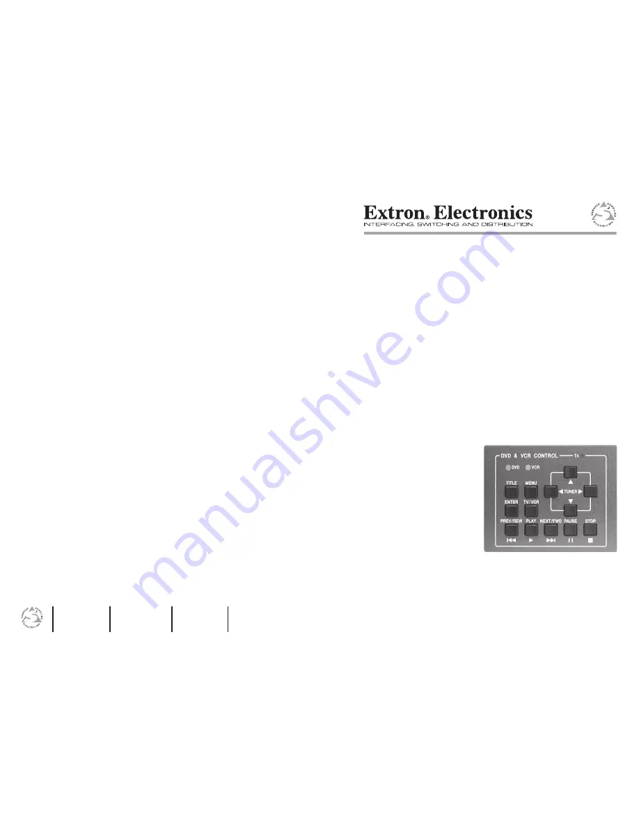
IRCM-DV+ Control Module

Содержание IRCM-DVplus

Страница 1: ...ax 31 33 453 4050 Extron Electronics Asia 135 Joo Seng Road 04 01 PM Industrial Building Singapore 368363 65 6383 4400 Fax 65 6383 4664 Extron Electronics Japan Daisan DMJ Building 6F 3 9 1 Kudan Minami Chiyoda ku Tokyo 102 0074 Japan 81 3 3511 7655 Fax 81 3 3511 7656 www extron com 2002 Extron Electronics All rights reserved Control Accessory 68 689 01 Rev A 07 02 Printed in the USA IRCM DV Contr...

Страница 2: ...werden können Wartung Alle Wartungsmaßnahmen sollten nur von qualifiziertem Servicepersonal durchgeführt werden Die internen Komponenten des Gerätes sind wartungsfrei Zur Vermeidung eines elektrischen Schocks versuchen Sie in keinem Fall dieses Gerät selbst öffnen da beim Entfernen der Abdeckungen die Gefahr eines elektrischen Schlags und oder andere Gefahren bestehen Schlitze und Öffnungen Wenn d...

Страница 3: ...e power source Step 2 Install an electrical box or mud ring and cables Use cable clamps to hold cables in place for strain relief Trim back or insulate exposed cable shields with heat shrink to prevent short circuits Step 3 Set the DIP switches on each control module s circuit board For the IRCM DV select ON 1 2 ON 1 2 ON 1 2 ON 1 2 1 and 2 down off address 0 control module 1 2 1 up on 2 down off ...

Страница 4: ...e only A B C D E IR Modulated IR Ground MLC IR control port 110 feet 33 5 m maximum Connect up to 4 IR Emitters max D A Step 7 Connect the projector s RS 232 port to the MLC 206 Refer to the MediaLink Controllers User s Manual Step 8 Connect a MediaLink Switcher MLS to the MLC and to the projector if applicable Refer to the MediaLink Controllers User s Manual Step 9 Restore power to the MLC and ot...

Страница 5: ...IRCM DV Table of Contents Table of Contents cont d IRCM DV 1 Chapter One Introduction About the IRCM DV Features ii ...

Страница 6: ...nt panel controls on both a VCR and a DVD player and it uses infrared commands to control those devices The IRCM DV is referred to as module IRCM IRCM DV and control module in this manual The MLC to which the IRCM DV is connected must have MLC firmware version 1 04 or higher in order to work with the IRCM DV To set up the IRCM DV you must use MediaLink Control Software version 2 0 or higher Featur...

Страница 7: ...on IR RCM captive screw connector of an MLC Do not install more than one IR Link 2 Control module address identification DIP switches Set these switches to identify the address es of each module Each module must have a unique address Each IRCM DV is assigned two addresses simultaneously 1 and 2 or 3 and 4 One address address 2 for example stores the VCR information the other address address 1 for ...

Страница 8: ...User s Manual for details Connectors are included with each control module but the cable must be purchased separately See the illustration on the next page for reference and see appendix A for cable part numbers and conductor gauges 3 Plug the 5 pole connector into either one of the control module s communications connectors 2 5 2 4 A D B C E A D B C E ON 1 2 A D B C E A D B C E MLC IR RCM port A ...

Страница 9: ...R TITLE MENU TV VCR DVD VCR 5 1 2 3 4 IRCM DV Front 1 DVD LED This yellow LED light emitting diode lights while the MLC s input associated with the DVD player is selected 2 VCR LED This yellow LED lights while the MLC s input associated with the VCR is selected LEDs 1 and 2 turn off when an input that is not associated with that part of the IRCM DV is selected The corresponding MLC input must be s...

Страница 10: ...See the following pictures The DVD and VCR portions of the IRCM DV cannot share the same input You must assign a different input number to each half of the module Associating the IRCM DV s DVD half with an MLC input Associating the IRCM DV s VCR half with an MLC input 4 For each half DVD and VCR of the IRCM DV select click on the control module button such as Play or Stop that you wish to program ...

Страница 11: ...efore either part DVD or VCR of the IRCM DV can be activated and can control the DVD or VCR 4A If the TX LED does not light when a button is pressed check the captive screw connector wiring at both the MLC and the control module If the conductor assignments are not the same at both ends the circuits may be damaged if power is applied to the wrong pole and the control module will not turn on Verify...

Страница 12: ... Installation and Operation Installation and Operation cont d IRCM DV A Appendix A Specifications Part Numbers Accessories and Dimensions Specifications Included Parts Accessories Cables Dimensions Index 2 12 ...

Страница 13: ...18 AWG white and violet shielded single strands for signals 22 AWG drain wire 24 AWG Specifications General Power 12VDC from an MLC 206 s power supply or a System 5xi Temperature humidity Storage 40 to 158 F 40 to 70 C 10 to 90 non condensing Operating 32 to 122 F 0 to 50 C 10 to 90 non condensing Rack mount Yes with optional faceplate and furniture wall mountable with optional faceplates or AAP w...

Страница 14: ...g 2 11 IR Broadcaster wiring 2 6 IR Emitter cabling 2 6 IR Emitters troubleshooting 2 11 IR learning instructions 2 9 IR Link 2 4 IR RCM port MLC 2 4 M MediaLink Control Program and IR learning 2 9 MediaLink Control Program setup troubleshooting 2 11 mounting 2 11 P parts A 3 power requirement A 2 R rear panel 2 3 S specifications A 2 T testing 2 10 troubleshooting 2 10 U UL requirements 2 2 W wal...

Страница 15: ...Control Modules Specifications Part s Dimensions Specifications Part Numbers Accessories cont d A 6 ...

Отзывы: