DXP HD 4K PLUS Series • Operation
25
Locking and Unlocking the Front Panel
(Executive Modes)
The matrix switchers have three levels of front panel security lock that limit the operation of
the switcher from the front panel:
•
Lock mode 0
— The front panel is completely unlocked. All front panel functions are
available.
NOTE:
Opening PCS sets the lock mode to 0.
•
Lock mode 1
— All changes are locked from the front panel (except for setting lock
mode 2). Some functions can be viewed. When the DXP enters mode 1, the
Video
and
Audio
LEDs blink twice.
•
Lock mode 2
— Basic functions are unlocked. Advanced features, except for
switching to lock mode 1, are locked and can only be viewed. When the DXP enters
mode 2, the
Esc
,
Video
, and
Audio
LEDs blink twice. This is the default mode.
Basic functions include:
•
Making ties
•
Saving and recalling presets
•
Changing lock modes
Advanced functions include:
•
Setting video and audio output mutes
•
Setting the rear panel Remote RS 232 port protocol and baud rate
NOTE:
The switcher is shipped from the factory in lock mode 2.
Selecting Front Panel Lock Mode 2 or Toggling between Lock Modes 2 and 0
NOTES:
•
If the switcher is in lock mode 0 or 1, this procedure selects mode 2.
•
If the switcher is in lock mode 2, this procedure selects mode 0 (unlocks the
switcher).
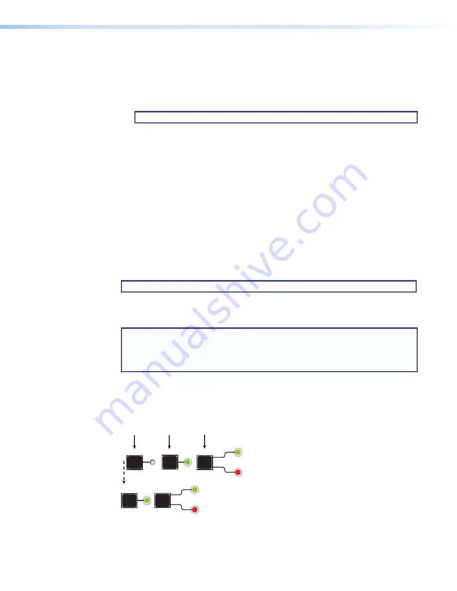
Toggle the front panel lock on and off by pressing and holding the
Enter
,
I/O
, and
Esc
buttons simultaneously until the following LEDs blink twice (approximately 3 seconds).
•
The Esc, Video, and Audio LEDs blink twice if the DXP is now in lock mode
2
.
•
The Video and Audio LEDs blink twice if the DXP is now in lock mode
0
.
I/O
ENTER
ESC
Press and
hold
simultaneously.
3 seconds
I/O
VIDEO
AUDIO
ESC
The LEDs blink twice.
Release the buttons.
VIDEO
AUDIO
Figure 24.
Switching between Front Panel Lock Modes 0 and 2


