background image

The airflow direction of the power supply must match that of the installed fan assemblies. All must be either exhaust or intake.

NOTE

Power supplies are hot-swappable. However, they should be inserted or removed without a power cord being connected to a
power source to avoid damage.

CAUTION
Ensure that the airflow direction of the power supply unit matches that of the installed fan tray. The power supplies and fan
trays are clearly labeled with either a green arrow with an "E", or an orange arrow with an "I."

Inserting a new AC power supply

Use the following steps to install an AC power supply in the SLX 9540 device.
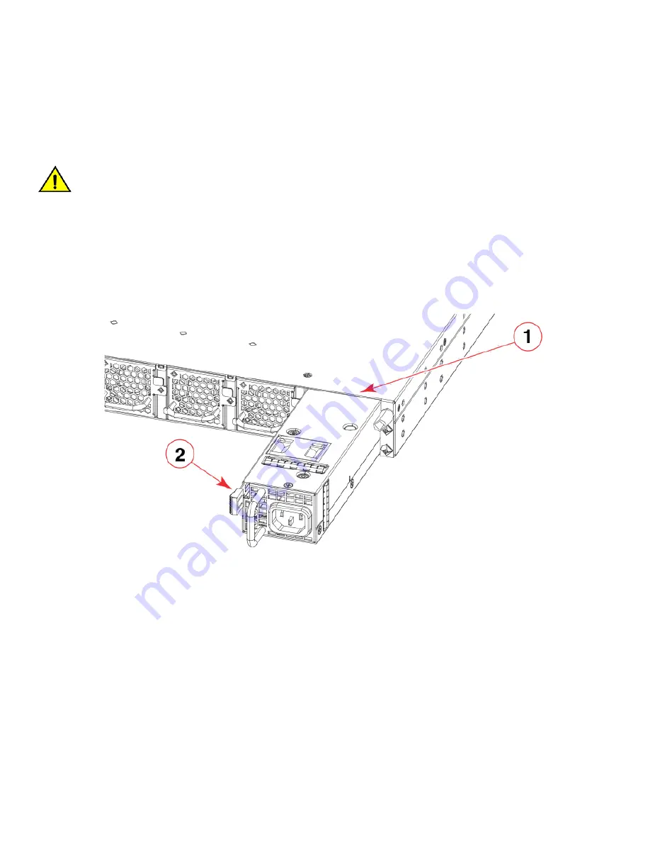
FIGURE 44 

Installing an AC power supply unit

1.

Power supply slot

2.

Release lever

1. If replacing a power supply, remove the previously installed power supply from the appropriate slot by pressing the release lever

and pulling the power supply handle.

2. If installing a new power supply into a slot covered with a filler panel:

1. Press the release lever on the filler panel.
2. Remove the filler panel.

3. Before opening the package that contains the power supply, touch the bag to the switch casing to discharge any potential static

electricity. Extreme recommends using an ESD wrist strap during installation.

4. Remove the power supply from the anti-static shielded bag.
5. Holding the power supply level, guide it into the carrier rails on each side and gently push it all the way into the slot, ensuring

that it firmly engages with the connector and the release lever clicks into its locked position.

Inserting a new AC power supply

ExtremeSwitching SLX 9540 Hardware Installation Guide

9036360-00 Rev AB

81

Содержание ExtremeSwitching SLX 9540

Страница 1: ...ExtremeSwitching SLX 9540 Hardware Installation Guide 9036306 00 Rev AB March 2020 ...

Страница 2: ...o are trademarks or registered trademarks of Extreme Networks Inc in the United States and or other countries All other names including any product names mentioned in this document are the property of their respective owners and may be trademarks or registered trademarks of their respective companies owners For additional information on Extreme Networks trademarks please see www extremenetworks co...

Страница 3: ...eral precautions 17 ESD precautions 18 Power precautions 18 Lifting precautions 19 Laser precautions 19 Facility requirements 19 Electrical considerations 19 Environmental considerations 20 Location considerations 20 Cable management recommendations 20 Quick installation checklist 21 Shipping carton contents 22 Mounting the Device 23 Mounting options 23 Mounting precautions 23 Standalone installat...

Страница 4: ...ment kit 60 Transceivers and Cables 61 Supported transceivers and cables 61 Time and items required 61 Precautions specific to transceivers and cables 62 Cleaning the fiber optic connectors 62 Managing cables 63 Installing an SFP transceiver 63 Replacing an SFP transceiver 65 Installing a QSFP28 transceiver 67 Replacing a QSFP28 transceiver 69 Breakout cables 70 Verifying transceiver operation 71 ...

Страница 5: ...Serial port specifications pinout RJ 45 94 Serial port specifications pinout mini USB 94 Serial port specifications protocol 94 Memory specifications 94 Regulatory compliance EMC 95 Regulatory compliance safety 95 Regulatory compliance environmental 95 Regulatory Statements 97 CE statement 97 China ROHS 97 BSMI statement Taiwan 97 Canadian requirements 98 China CCC statement 98 Europe and Australi...

Страница 6: ...ExtremeSwitching SLX 9540 Hardware Installation Guide 6 9036360 00 Rev AB ...

Страница 7: ...en traffic might be interrupted or the device might reboot CAUTION A Caution statement alerts you to situations that can be potentially hazardous to you or cause damage to hardware firmware software or data DANGER A Danger statement indicates conditions or situations that can be potentially lethal or extremely hazardous to you Safety labels are also attached directly to products to warn of these c...

Страница 8: ...mand examples If a backslash separates two lines of a command input enter the entire command at the prompt without the backslash Documentation and Training To find Extreme Networks product guides visit our documentation pages at Current Product Documentation www extremenetworks com documentation Archived Documentation for earlier versions and legacy products www extremenetworks com support documen...

Страница 9: ...ons You can subscribe to email notifications for product and software release announcements Vulnerability Notices and Service Notifications 1 Go to www extremenetworks com support service notification form 2 Complete the form with your information all fields are required 3 Select the products for which you would like to receive notifications NOTE You can modify your product selections or unsubscri...

Страница 10: ...ExtremeSwitching SLX 9540 Hardware Installation Guide 10 9036360 00 Rev AB ...

Страница 11: ...6 100 GbE 40 GbE ports SLX OS 17r 1 00 Yes BR SLX 9540 48S DC F SLX 9540 48S Switch DC with Front to Back airflow Supports 48 10 GbE 1 GbE 6 100 GbE 40 GbE ports SLX OS 17r 1 00 Yes BR SLX 9540 48S AC R SLX 9540 48S Switch AC with Back to Front airflow Supports 48 10 GbE 1 GbE 6 100 GbE 40 GbE ports SLX OS 17r 1 00 Yes BR SLX 9540 48S DC R SLX 9540 48S Switch DC with Back to Front airflow Supports...

Страница 12: ...escription Introduced OS Currently supported XBR 3250CFM FAN F SLX FIXED FAN AC F2B AIRFLOW SLX OS 17r 1 00 Yes XBR 3250CFM FAN R SLX FIXED FAN AC B2F AIRFLOW SLX OS 17r 1 00 Yes The following table list the SLX 9540 Switch supported Rack Mount Kits NOTE XEN R000296 and XEN R000294 can also be used with SLX fixed however the box includes XBR R000297 at shipment TABLE 5 Supported SLX 9540 Switch Ra...

Страница 13: ...Tbps Forwarding capacity 720 Mpps Airflow Front to back or back to front orderable option Fan module slots 6 shipped with 5 Fan FRUs 4 1 redundancy Maximum AC power supply rating 650 W Power supply module slots 2 1 1 redundancy Height 1 72 in 4 37 cm 1 RU Width 17 32 in 44 00 cm Depth chassis only without cable management or fan handles 17 51 in 44 47 cm Weight chassis only 19 84 lb 9 00 kg The fo...

Страница 14: ...w of the SLX 9540 Switch FIGURE 2 SLX 9540 Switch rear view with power supply and fan assemblies For more device details refer to ExtremeSwitching SLX 9540 Technical Specifications on page 91 Hardware features ExtremeSwitching SLX 9540 Hardware Installation Guide 14 9036360 00 Rev AB ...

Страница 15: ...ort side of the SLX 9540 Switch showing the LEDs FIGURE 4 Port side view of the SLX 9540 Switch 1 Management port link LED 2 Management port speed LED 3 Upper LEDs 0 3 for QSFP ports 49 51 53 4 Lower LEDs 0 3 for QSFP ports 50 52 54 5 SFP Port LEDs for ports 1 48 6 Status LED 7 Power LED Nonport side view of the SLX 9540 Switch The following illustration shows the rear view or nonport side of the ...

Страница 16: ...the device using any of the management options listed in the following table TABLE 7 Management options for the device Management tool Out of band support In band support Reference documents Command line interface CLI Ethernet or serial connection N A ExtremeSwitching SLX OS Management Configuration Guide REST or NETCONF YANG APIs Ethernet connection Yes ExtremeSwitching SLX OS Management Configur...

Страница 17: ...tions DANGER Be careful not to accidently insert your fingers into the fan tray while removing it from the chassis The fan may still be spinning at a high speed CAUTION Changes or modifications made to this device that are not expressly approved by the party responsible for compliance could void the user s authority to operate the equipment CAUTION Disassembling any part of the power supply and fa...

Страница 18: ...and other electronic devices To avoid damage keep static sensitive devices in their static protective packages until you are ready to install them CAUTION Before plugging a cable into any port be sure to discharge the voltage stored on the cable by touching the electrical contacts to ground surface Power precautions DANGER If the installation requires a different power cord than the one supplied w...

Страница 19: ... components never attempt to lift the chassis using the fan or power supply handles These handles were not designed to support the weight of the chassis Laser precautions DANGER All fiber optic interfaces use Class 1 lasers DANGER Laser Radiation Do Not View Directly with Optical Instruments Class 1M Laser Products DANGER Use only optical transceivers that are qualified by Extreme Networks Inc and...

Страница 20: ...40 Switch should be installed with its top and bottom covers parallel to the floor The SLX 9540 Switch should not be installed upside down Allow a minimum of 3 in of space between the front and the back of the device and walls or other obstructions for proper airflow Allow at least 3 in of space at the front and back of the device for the twisted pair fiber optic and power cabling Allow access spa...

Страница 21: ...omizing an SLX 9540 Switch baseline chassis 1 Install at least one power supply unit 2 Install at least five fans Refer to Inserting a new AC power supply on page 81 Refer to Inserting a new DC power supply on page 82 Refer to Inserting a new fan assembly on page 87 3 Mount the device on a desktop or in a rack Refer to Installing the device in a rack on page 24 4 Attach a terminal or PC to the dev...

Страница 22: ... with an accessory kit containing the following items XBR R000297 four post rack mount kit Serial cable with an RJ 45 connector Two 6 ft power cord Power cord retainer clip Rubber feet required for setting up the device as a standalone unit China RoHS Hazardous Toxic Substance statement EULA Read Me document USB drive 8G Shipping carton contents ExtremeSwitching SLX 9540 Hardware Installation Guid...

Страница 23: ...N R000294 The two post rack kit supports various mounting positions In a four post EIA rack using the Universal Four Post Rack Kit XEN R000296 The rack kit can be used to install devices in EIA racks that are between L 13 7 to 81 28 cm deep L 5 0 to 32 0 in where L is the chassis depth NOTE Review the Safety Precautions Safety precautions on page 17 before mounting the device NOTE These rack mount...

Страница 24: ...housing the device is adequately secured to prevent it from becoming unstable or falling over NOTE You need a 2 Phillips screwdriver for installation Before mounting the device in a rack pay particular attention to the following factors Temperature Because the temperature within a rack assembly may be higher than the ambient room temperature check that the rack environment temperature is within th...

Страница 25: ...lush mount rack kit included with the switch Time and items required Allow 15 to 30 minutes to complete the installation The following items are required to install the device using the Universal Four Post Rack Kit 2 Phillips torque screwdriver 1 4 inch slotted blade torque screwdriver Parts list The following parts are provided with the four post flush mount rack kit XBR R000297 Verify that the i...

Страница 26: ...specified in the procedure Using longer screws can damage the device Flush front mounting CAUTION The device must be turned off and disconnected from the fabric during this procedure Complete the following tasks to install the device in a four post rack 1 Attaching the front brackets on page 27 2 Installing the device in the rack on page 27 Four post rack mount kit installation XBR R000297 Extreme...

Страница 27: ... 8 32 x 5 16 in screws to a torque of 15 in lb 17 cm kg FIGURE 7 Attaching the front brackets to the device 1 The SLX 9540 device 2 Front brackets 3 Screws 8 32 x 5 16 in flathead Phillips Installing the device in the rack Complete the following steps to install the device in the rack 1 Position the device in the rack as shown in the figure below providing temporary support under the device until ...

Страница 28: ...r bracket into the right front bracket and the left rear bracket into the left front bracket 2 Adjust the rear brackets to the rack depth 3 Attach the right rear bracket to the right rear rack post using three 10 32 x 5 8 in panhead screws and three retainer nuts as shown in the figure below Use the three holes in the bracket 4 Attach the left rear bracket to the left rear rack post using three 10...

Страница 29: ...evice in a two post rack With the port side flush with the front posts With the posts mounted to the mid section of the device Observe the following when mounting this device Two people are required to install the device in a rack One person should hold the device while the other screws in the front and rear brackets Before mounting your device review any specific installation and facility require...

Страница 30: ...e required to install the device in a rack One person holds the device while the other screws in the front and rear L brackets Time and items required Allow 15 to 30 minutes to complete the installation The following items are required to install the device using the Universal Two Post Rack Kit 2 Phillips torque screwdriver 1 4 inch slotted blade torque screwdriver Parts list The following parts a...

Страница 31: ... the kit Note that not all parts may be used with certain installations depending on the device type CAUTION Use the screws specified in the procedure Using longer screws can damage the device Flush front mounting Observe the following notes when using this procedure The device must be turned off and disconnected from the fabric during this procedure The illustrations in this document show a 1U de...

Страница 32: ...he front brackets to the device 1 Position the right front bracket with the flat side against the right side of the device as shown in Figure 11 2 Insert four 8 32 x 5 16 in flathead screws through the vertically aligned holes in the bracket and then into the holes on the side of the device Use the upper and lower screw holes leaving the center holes empty 3 Repeat step 1 and step 2 to attach the ...

Страница 33: ...ttaching front brackets to a rack 1 Screws 10 32 x 5 8 in panhead Phillips 2 Retainer nuts 10 32 Attaching the rear brackets to the rack Complete the following steps to attach the rear brackets to the rack 1 Select the proper length bracket for your post width If your posts are three to five inches wide use the brackets marked 3 5 INCH If your posts are five to six inches wide use the brackets mar...

Страница 34: ...racket to the right rear of the device and use four 8 32 x 5 16 in panhead screws to attach the bracket to the device as shown in Figure 14 Be sure to insert the screws through the upper and lower slots in the bracket 2 Align the left rear bracket to the left rear of the device and use four 8 32 x 5 16 in panhead screws to attach the bracket to the device Again use the upper and lower slots in the...

Страница 35: ...eference only and may not show the actual device Complete the following tasks to install the device in a rack 1 Attaching the front brackets to the device on page 35 2 Attaching the front brackets to the rack on page 36 3 Attaching the rear brackets to the rack on page 37 4 Attaching the rear brackets to the device on page 38 Attaching the front brackets to the device Complete the following steps ...

Страница 36: ...lips Attaching the front brackets to the rack Complete the following steps to install the device in the rack 1 Position the device in the rack as shown in Figure 16 providing temporary support under the device until the rack kit is fully secured to the rack 2 Attach the right front bracket to the right rack upright using two 10 32 x 5 8 in screws and two retainer nuts Use the upper and lower holes...

Страница 37: ...f your posts are five to six inches wide use the brackets marked 5 6 INCH 2 Position the right rear bracket in the right rear of the device as shown in the following figure Whether you are using the 3 5 inch or the 5 6 inch bracket the rear end of the bracket will be flush with the back of the device 3 Attach the brackets to the right rack upright using two 10 32 x 5 8 in panhead screws and two re...

Страница 38: ...t rear bracket to the right rear of the device and use four 8 32 x 5 16 in panhead screws to attach the bracket to the device as shown in Figure 18 Be sure to insert the screws through the upper and lower slots in the bracket 2 Align the left rear bracket to the left rear of the device and use four 8 32 x 5 16 in panhead screws to attach the bracket to the device Again use the upper and lower slot...

Страница 39: ...th the front posts With the nonport side flush with the rear posts in a recessed position A recessed position allows a more gradual bend in the fiber optic cables connected to the switch and less interference in the aisle at the front of the rack TABLE 9 Space requirements Chassis with port side side vents Notes Chassis depth Minimum rack depth Maximum rack depth No Applicable to port side and non...

Страница 40: ...irements Chassis with port side side vents Notes Chassis depth Minimum rack depth Maximum rack depth No Applicable to port side and nonport side flush mounts L L 12 7 cm L 5 in 81 28 cm 32 in Yes Applicable to port side flush mounts L L 12 7 cm L 5 in 81 28 cm 32 in Yes Applicable to nonport side flush mounts L L 81 28 cm 32 in Note that if chassis depth L is less than 40 64 cm 16 in the chassis w...

Страница 41: ...on brackets long 2 6 Screw 8 32 x 5 16 in panhead Phillips 8 7 Screw 8 32 x 5 16 in flathead Phillips 16 8 Screw 8 32 x 5 16 in flathead Phillips 16 9 Screw 10 32 x 5 8 in panhead Phillips 8 10 Retainer nut 10 32 8 Installing the Universal Four Post Rack Kit XEN R000296 ExtremeSwitching SLX 9540 Hardware Installation Guide 9036360 00 Rev AB 41 ...

Страница 42: ...o the device on page 43 3 Installing the device in the rack on page 44 4 Attaching the rear brackets to the extensions on page 45 5 Attaching the rear brackets to the rack posts on page 46 Attaching the front brackets Complete the following steps to attach the front brackets to the device 1 Position the right front bracket with the flat side against the right side of the device at the front of the...

Страница 43: ...he proper length bracket extension for your rack depth 2 Position the right bracket extension along the side of the device as shown in Figure 21 3 Insert four 8 32 x 5 16 in flathead screws through the vertically aligned holes in the bracket extension and then into the holes on the side of the device Use the upper and lower screw holes leaving the center holes empty 4 Repeat step 2 and step 3 to a...

Страница 44: ...viding temporary support under the device until the rail kit is secured to the rack 2 Attach the right front bracket to the right front rack post using two 10 32 x 5 8 in panhead screws and two retainer nuts Use the upper and lower holes in the bracket 3 Attach the left front bracket to the left front rack post using two 10 32 x 5 8 in panhead screws and two retainer nuts Use the upper and lower h...

Страница 45: ... the correct bracket for the depth of your rack 1 Select the proper length rear bracket for your rack depth 2 Slide the right rear bracket onto the right bracket extension as shown in the following figure 3 Attach the brackets using four 6 32 x 1 4 in panhead screws If possible leave at least one empty vertical pair of holes between the screws for better support 4 Repeat step 2 and 3 to attach the...

Страница 46: ...rear brackets to the rack posts 1 Attach the right rear bracket to the right rear rack post using two 10 32 x 5 8 in panhead screws and two retainer nuts as shown in Figure 24 Use the upper and lower holes in the bracket 2 Attach the left rear bracket to the left rear rack post using two 10 32 x 5 8 in panhead screws and two retainer nuts Use the upper and lower holes in the bracket Installing the...

Страница 47: ... 1U device but the instructions are the same for a 2U device The illustrations in the rack installation procedures are for reference only and may not show the actual device Complete the following tasks to install the device in a four post rack 1 Attaching the front brackets to the rear of the device on page 48 2 Attaching the extensions to the front of the device on page 48 3 Installing the device...

Страница 48: ...ten all the 8 32 x 5 16 in screws to a torque of 15 in lb 17 cm kg FIGURE 25 Attaching the front brackets to the rear of the device 1 The device 2 Front brackets 3 Screws 8 32 x 5 16 in flathead Phillips Attaching the bracket extensions to the front of the device Complete the following steps to attach the bracket extensions to the front of the device There are medium and long extension brackets th...

Страница 49: ...ion the device in the rack as shown in Figure 27 providing temporary support under the device until the rail kit is secured to the rack 2 Attach the right front bracket to the right rear rack post using two 10 32 x 5 8 in panhead screws and two retainer nuts Use the upper and lower holes in the bracket 3 Attach the left front bracket to the left rear rack post using two 10 32 x 5 8 in panhead scre...

Страница 50: ... this step 1 Select the proper length rear bracket for your rack depth 2 Slide the right rear bracket onto the right extension The short rear brackets are shown in Figure 28 Use the first and third vertical pairs of holes for the screws Refer to Figure 29 for the positioning of the short or long brackets and screws 3 Attach the brackets using four 6 32 x 1 4 in panhead screws 4 Repeat step 2 and s...

Страница 51: ...hing the rear brackets to the extensions at the front of the device 1 Rear brackets short 2 Screws 6 32 x 1 4 in panhead Phillips FIGURE 29 Attaching the short or long rear brackets to the extensions Installing the Universal Four Post Rack Kit XEN R000296 ExtremeSwitching SLX 9540 Hardware Installation Guide 9036360 00 Rev AB 51 ...

Страница 52: ...e 30 Use the upper and lower holes in the bracket 2 Attach the left rear bracket to the left front rack post using two 10 32 x 5 8 in screws and two retainer nuts Use the upper and lower holes in the bracket 3 Tighten all the 10 32 x 5 8 in screws to a torque of 25 in lb 29 cm kg FIGURE 30 Attaching the rear brackets to the front rack posts 1 Screws 10 32 x 5 8 in panhead Phillips 2 Retainer nuts ...

Страница 53: ...ishing an Ethernet connection you can complete the device configuration using a serial or Telnet session Refer to Establishing an Ethernet connection on page 57 for more information Customize the chassis and host names Use the switch attributes chassis name and switch attributes host name commands to change the default host name For more information refer to Customizing the chassis and host names ...

Страница 54: ...ws An unused IP address with corresponding subnet mask and gateway address A serial cable provided with an RJ 45 connector Two Ethernet cables one per management module Optional Access to an FTP server or USB device for backing up uploading or downloading the device configuration or collecting diagnostic output data Optional An Extreme USB drive for backing up uploading or downloading the device c...

Страница 55: ...t the device is powered on by verifying that all power LED indicators on the management interface power supply and fan modules display a steady green light 2 Connect the RJ 45 serial cable provided with the device to the management Ethernet port of the device FIGURE 31 Port side view of the SLX 9540 Switch 1 10 100 1000Base T RJ 45 management Ethernet port 2 SFP ports 1 48 3 QSFP28 ports 49 54 4 R...

Страница 56: ...passwords for switch default accounts now Use Control C to exit or press Enter key to proceed 7 Press Enter to step through a procedure to change the passwords as shown in the following example To skip modifying the password press Ctrl C Warning Access to the Root and Factory accounts may be required for proper support of the switch Please ensure the Root and Factory passwords are documented in a ...

Страница 57: ...IPv6 address enter the network information in colon separated notation as prompted after the ipv6 address operand device config interface Management 1 device config Management 1 no ip address dhcp device config Management 1 ipv6 address fd00 60 69bc 832 e61f 13ff fe67 4b94 64 5 Return to privileged EXEC mode by entering exit device config exit device 6 To display the configuration use the show run...

Страница 58: ...owing task The chassis and host names can be up to 30 characters long can include letters numbers hyphens and underscore characters and must begin with a letter Extreme recommends that you customize the chassis name for each platform because some of the system logs refer to the platform by its chassis name 1 Log in to the device using one of the following methods A serial console connection to the...

Страница 59: ... name for your device 4 Optional Enter ip dns name server ip address where ip address is the IP address of the DNS server Setting the date and time Date and time are used for logging events The operation of the device does not depend on the date and time an Extreme device with an incorrect date and time value functions properly Because the date and time are used for logging error detection and tro...

Страница 60: ...e for downloading to a replacement chassis 1 Log in to the device using one of the following methods A serial console connection to the active management module The active management module has the LED labeled ACTIVE on the front panel illuminated in blue A command line interface CLI session using the chassis management IP address 2 Log in to the device using admin as your login name If you have n...

Страница 61: ...vers and cables that is supported by this device refer to the Extreme Ethernet Optics Family Datasheet on https cloud kapostcontent net pub a070d154 d6f1 400b b2f0 3d039ae2f604 data center ethernet optics data sheet and to the current Extreme SLX OS18r 2 00 for SLX 9540 Release Notes Time and items required The installation or replacement procedure for one transceiver takes less than 5 minutes Ens...

Страница 62: ...TION Before plugging a cable into any port be sure to discharge the voltage stored on the cable by touching the electrical contacts to ground surface Cleaning the fiber optic connectors To avoid problems with the connection between the fiber optic transceiver SFP QSFP or QSFP28 and the fiber cable connectors Extreme strongly recommends cleaning both connectors each time you disconnect and reconnec...

Страница 63: ...ay from the LEDs Do not route the cables in front of air vents Use Velcro type straps to secure and organize fiber optic cables Route the cables away from LEDs to keep them visible Use the cable management comb that attaches to the chassis for simple cable management The comb can be installed without service disruption CAUTION Before plugging a cable into any port be sure to discharge the voltage ...

Страница 64: ...hing mechanism clicks FIGURE 34 Installing an SFP transceiver with pull tab into the interface module port 1 Pull tab 2 Transceiver If the transceiver uses a bail latch mechanism 10 GbE transceivers only ensure that the bail wire handle is in the unlocked position grasp the transceiver and push it into the port until firmly seated Close the bail to latch the transceiver in the slot Installing an S...

Страница 65: ...sceiver until the latching mechanism clicks NOTE Cables are keyed so that they can be inserted in only one way If a cable does not slide in easily ensure that it is correctly oriented Do not insert any unsupported cable intended for an other type of transceiver into a regular SFP transceiver You may damage the cable as well as the transceiver Replacing an SFP transceiver Complete the following ste...

Страница 66: ...ghtly using the bail and then gasp the transceiver with your fingers and slide it straight out of the port FIGURE 36 Installing an SFP transceiver with bail latch into the interface module port 1 Bail If transceiver has a pull tab grasp the pull tab and pull the transceiver straight out from the port NOTE Grasp the pull tab near the body of the transceiver to reduce the chances of bending the pull...

Страница 67: ...ligned with the slot in the transceiver Insert the cable into the transceiver until the latching mechanism clicks Cables are keyed so that they can be inserted in only one way If a cable does not slide in easily ensure that it is correctly oriented Installing a QSFP28 transceiver While non Extreme optics are supported Extreme qualified transceivers are recommended The port might not become operati...

Страница 68: ...ic Rapid flash link with traffic Slow flash one second on one second off beaconing feature 2 Position the cable so that the key the ridge on one side of the cable connector is aligned with the slot in the transceiver Insert the cable into the transceiver until the latching mechanism clicks NOTE If your transceiver has an integrated cable you do not need to install a cable NOTE Cables are keyed so ...

Страница 69: ...ing the transceiver body 3 To insert the replacement transceiver use the pull tab to carefully push the transceiver into the port Transceivers are keyed so that they can only be inserted with the correct orientation If a transceiver does not slide in easily ensure that it is correctly oriented Gently push the correctly oriented QSFP28 transceiver until the latching mechanism clicks NOTE The follow...

Страница 70: ...ore information Breakout cables The copper breakout cables are terminated with optical connectors and are available in 1m 3m 5m and greater lengths No additional connectors or cabling are required when using the copper breakout When using the fiber breakout cables additional 10Gb optics are required For the SLX 9540 device interfaces 0 49 to 0 54 support up to 24 10GbE ports in breakout mode by us...

Страница 71: ...d and configured the ports for Ethernet connectivity and connected the cable to another active port the LED becomes solid green When traffic is detected on the port the light becomes blinking green You can also enter the show interface status and show ip interface brief commands to verify proper transceiver operation Verifying transceiver operation ExtremeSwitching SLX 9540 Hardware Installation G...

Страница 72: ...ExtremeSwitching SLX 9540 Hardware Installation Guide 72 9036360 00 Rev AB ...

Страница 73: ...s refer to the Extreme SLX OS Monitoring Configuration Guide for the SLX 9540 Switch show chassis show system show slots show linecard show environment fan show environment power show environment sensor show environment temp LED activity interpretation The SLX 9540 Switch has the following LEDs on the front panel One power single color status LED green One status bicolor status LED green and amber...

Страница 74: ...ector The Power supply LEDs are integrated with the PSU The 10G and 100G Port LEDs are surface mount types The are visible to the front panel TABLE 13 SLX 9540 Switch LED Indications LED Function state Meaning Possible cause Power Off No power Some Power rails are dropping below specification Green Valid power All monitored voltages are nominal Status bicolor Blinking Amber Green Attention TBD by ...

Страница 75: ... Amber Blinking Warning Power supply warning detected as per PMBus STATUS_X reporting bytes Amber Steady FAULT Power supply fault detected as per PMBus STATYS_X reporting bytes Fan Status LED On Fan FRU Off No Power Green Steady Fan operates per specification Green Blinking Amber Steady Fan failed Amber Blinking 10G 100G Port LEDs Green only Solid Off No Link Solid ON Link no traffic Link traffic ...

Страница 76: ...ExtremeSwitching SLX 9540 Hardware Installation Guide 76 9036360 00 Rev AB ...

Страница 77: ...mblies installed If a power supply or fan assembly fails it must be replaced as soon as possible NOTE AC and DC power supplies can be installed and used in the same device The power supplies in the SLX 9540 device chassis can be removed and replaced without special tools The device can continue operating during the replacement The device supports the following types of power supplies AC power supp...

Страница 78: ...FIGURE 42 AC power supply 1 Release lever 2 Power supply handle Power supply overview ExtremeSwitching SLX 9540 Hardware Installation Guide 78 9036360 00 Rev AB ...

Страница 79: ...with the device make sure you use a power cord displaying the mark of the safety agency that defines the regulations for power cords in your country The mark is your assurance that the power cord can be used safely with the device CAUTION Disassembling any part of the power supply and fan assembly voids the warranty and regulatory certifications There are no user serviceable parts inside the power...

Страница 80: ...rs ending with R Exhaust power supply and fan assembly with a green E label Pulls air from the port side of the switch and exhausts it out the nonport side Nonport side air exhaust Port side air intake Front to back port side to nonport side airflow Part numbers ending with F Time and items required Installing or removing and replacing a power supply should require less than five minutes to comple...

Страница 81: ...acing a power supply remove the previously installed power supply from the appropriate slot by pressing the release lever and pulling the power supply handle 2 If installing a new power supply into a slot covered with a filler panel 1 Press the release lever on the filler panel 2 Remove the filler panel 3 Before opening the package that contains the power supply touch the bag to the switch casing ...

Страница 82: ...ponsible for the location NOTE This equipment installation must meet NEC CEC code requirements Consult your local authorities for required regulations Use the following steps to install an DC power supply in the SLX 9540 device FIGURE 45 Installing an DC power supply unit 1 DC power supply terminals 2 Safety ground screw 1 Make sure that power is disconnected at the circuit breaker before proceedi...

Страница 83: ... ground screw 10 Using the handle on the power supply hold the power supply level and guide it into the power supply slot Gently push the power supply all the way into the slot ensuring that it firmly engages with the connector and the release lever clicks into its locked position When the SLX 9540 device is powered on the power LED on the front of the device should turn green to confirm that the ...

Страница 84: ... compliance with local regulations 2 Ensure that there is a good electrical connection to the grounding point on the rack no paint or isolating surface treatment 3 Crimp the included grounding lug to a grounding wire of at least 12 American Wire Gauge AWG The 12 AWG wire and grounding lug should be crimped together using a proper tool 4 Attach the 12 AWG stranded copper wire to the grounding termi...

Страница 85: ...nd power supply and any of the fan slots are unused you must cover them with filler panels NOTE Extreme Networks recommends that the SLX 9540 device operate with two power supplies and five fan assemblies installed If a power supply or fan assembly fails it must be replaced as soon as possible The fan assemblies in the SLX 9540 device chassis can be removed and replaced without special tools The d...

Страница 86: ... user serviceable parts inside the power supply and fan assembly CAUTION Ensure that the airflow direction of the power supply unit matches that of the installed fan tray The power supplies and fan trays are clearly labeled with either a green arrow with an E or an orange arrow with an I CAUTION If you do not install a module or a power supply in a slot you must keep the slot filler panel in place...

Страница 87: ...utes to complete The following items are required to replace a fan assembly New fan assembly must have the same airflow direction as the fan assembly being replaced 1 Phillips screwdriver Replacing a fan assembly When installing or replacing a fan assembly unit keep in mind the following Fan assemblies can be swapped in or out while the device is running The remaining fan assemblies provide enough...

Страница 88: ...ntains the new fan assembly touch the bag to the switch casing to discharge any potential static electricity It is recommended that you wear an ESD wrist strap during installation 4 Remove the fan assembly from the anti static shielded bag NOTE Do not force the installation If the fan assembly does not slide in easily ensure that it is correctly oriented before continuing 5 Holding the fan assembl...

Страница 89: ...lled and running Refer to LED activity interpretation on page 45 CAUTION If you do not install a module or a power supply in a slot you must keep the slot filler panel in place If you run the chassis with an uncovered slot the system will overheat Inserting a new fan assembly ExtremeSwitching SLX 9540 Hardware Installation Guide 9036360 00 Rev AB 89 ...

Страница 90: ...ExtremeSwitching SLX 9540 Hardware Installation Guide 90 9036360 00 Rev AB ...

Страница 91: ... natively and 10GbE 25GbE through breakout cables There are 6 x 100GbE ports 6 SFP ports The SFP ports can support 10GbE 1GbE interfaces There are 48 x SFP ports 48 Ethernet management port RJ 45 port with 10 100 1000 Mbps auto negotiating capability 1 LEDs System component Description Interface module LEDs Power Green Power OK off No power Status Green Status OK Amber Error Off Unexpected error L...

Страница 92: ...Unit 54 4 x 40 0 x 236 6 mm 0 76 Kg 1 672 lbs Environmental requirements Condition Operational Non operational Ambient temperature 5 C to 50 C 23 F to 122 F F2B 5 C to 55 C 23 F to 131 F B2F with 5 fan assemblies 40 C to 70 C 40 F to 158 F Relative humidity non condensing 5 to 95 at 50 C 122 F 5 to 95 at 70 C 158 F Altitude above sea level 0 to 3 000 m 9 843 ft safety 60 to 4 000 m 13 123 ft opera...

Страница 93: ...68 W 573 BTU hr 1 x 650 W AC 1 x 650 W DC 1 power supply 178 W 607 BTU hr 176 W 601 BTU hr 179 W 611 BTU hr 1 x 650 W AC 1 x 650 W DC 2 power supplies Power consumption maximum configuration All 100 GbE ports are linked up loading with 100 percent traffic rate Two power supplies and five fan assemblies Fans at high speed 100 VAC Input Input power 5 200 VAC Input Input power 5 48VDC Minimum number ...

Страница 94: ...d Not used 2 UART0_RX Debug port data received by SLX 3 UART0_TX Console port data transmitted by SLX 4 Reserved Not used 5 GND Ground Serial port specifications protocol Parameter Value Baud 9600 Data bits 8 Parity None Stop bits 1 Flow control None Memory specifications Parameter Type Size Main memory DDR4 16 GB Boot flash NOR Flash 32 MB SSD M 2 SATA III 2 slots 64 GB per slot Serial port speci...

Страница 95: ... 94 62 EC packaging and packaging waste EU 2006 66 EC batteries and accumulators and waste batteries and accumulators EU battery directive 1907 2006 of the European Parliament and of the Council of 18 December 2006 concerning the Registration Evaluation Authorisation and Restriction of Chemicals EU REACH Section 1502 of the Dodd Frank Wall Street Reform and Consumer Protection Act of 2010 U S Conf...

Страница 96: ...ExtremeSwitching SLX 9540 Hardware Installation Guide 96 9036360 00 Rev AB ...

Страница 97: ...to take corrective measures The standards compliance label on this device contains the CE mark which indicates that this system conforms to the provisions of the following European Council directives laws and standards Electromagnetic Compatibility EMC Directive 2014 30 EU Low Voltage Directive LVD 2014 35 EU EN 55032 EN 55024 European Immunity Requirements EN61000 3 2 JEIDA European and Japanese ...

Страница 98: ...ures Canadian requirements This Class A digital apparatus meets all requirements of the Canadian Interference Causing Equipment Regulations ICES 003 Class A Cet appareil numérique de la classe A est conforme à la norme NMB 003 du Canada China CCC statement Canadian requirements ExtremeSwitching SLX 9540 Hardware Installation Guide 98 9036360 00 Rev AB ...

Страница 99: ...t cause harmful interference to radio communications Operation of this equipment in a residential area is likely to cause harmful interference in which case the user will be required to correct the interference at the user s own expense Germany statement Machine noise information regulation 3 GPSGV the highest sound pressure level value is 70 0 dB A in accordance with EN ISO 7779 Maschinenlärminfo...

Страница 100: ...t is used in a domestic environment radio disturbance might arise When such trouble occurs the user might be required to take corrective actions Japan power cord English translation of above statement ATTENTION Never use the power cord packed with your equipment for other products VCCI statement ExtremeSwitching SLX 9540 Hardware Installation Guide 100 9036360 00 Rev AB ...

Страница 101: ...équipement PRECAUCIÓN Si se realizan cambios o modificaciones en este dispositivo sin la autorización expresa de la parte responsable del cumplimiento de las normas la licencia del usuario para operar este equipo puede quedar anulada CAUTION Disassembling any part of the power supply and fan assembly voids the warranty and regulatory certifications There are no user serviceable parts inside the po...

Страница 102: ...ur éviter de l endommager PRECAUCIÓN Para evitar que se dañe el puerto serie mantenga la cubierta colocada sobre el puerto cuando no lo utilice CAUTION Never leave tools inside the chassis VORSICHT Lassen Sie keine Werkzeuge im Chassis zurück MISE EN GARDE Ne laissez jamais d outils à l intérieur du châssis PRECAUCIÓN No deje nunca herramientas en el interior del chasis CAUTION If you do not insta...

Страница 103: ...e clé ou un outil spécial ou d autres moyens de sécurité et qui est contrôlée par les autorités responsables du site PRECAUCIÓN Todos los dispositivos con fuentes de alimentacion de corriente continua CC han sido diseñados únicamente para su instalación en áreas restringidas zonas de acceso restringido Se entiende como área de acceso restringido un lugar al que solo puede acceder personal de servi...

Страница 104: ...instrumento Compare esta suma con el límite nominal para el circuito Las capacidades nominales de corriente máximas están generalmente impresas en los instrumentos cerca de los conectores de corriente de entrada CAUTION Before plugging a cable into any port be sure to discharge the voltage stored on the cable by touching the electrical contacts to ground surface VORSICHT Bevor Sie ein Kabel in ein...

Страница 105: ... besteht Explosionsgefahr Entsorgen Sie gebrauchte Komponenten mit Batterien gemäß den lokalen Auflagen und Vorschriften DANGER Les batteries utilisées pour la sauvegarde de l horloge et de la mémoire ne sont pas remplaçables par l opérateur Il y a risque d explosion si la batterie est remplacée par une d un type incompatible Jetez recyclez les batteries conformément aux normes locales PELIGRO Las...

Страница 106: ...possible que le ventilateur tourne encore à grande vitesse PELIGRO Procure no insertar los dedos accidentalmente en la bandeja del ventilador cuando esté desmontando el chasis El ventilador podría estar girando a gran velocidad DANGER For safety reasons the ESD wrist strap should contain a series 1 megaohm resistor GEFAHR Aus Sicherheitsgründen sollte ein EGB Armband zum Schutz von elektronischen ...

Страница 107: ...LIGRO Este conmutador podría tener más de un cable de alimentación Para reducir el riesgo de sufrir una descarga eléctrica desconecte todos los cables de alimentación antes de proceder con la reparación DANGER Use safe lifting practices when moving the product GEFAHR Beim Bewegen des Produktes ist auf eine sichere Hubtechnik zu achten DANGER Utiliser des techniques de levage sûres pour déplacer le...

Страница 108: ...works Inc zugelassen sind und die die Anforderungen gemäß FDA Class 1 Radiation Performance Standards in 21 CFR Unterkapitel I sowie IEC 60825 und EN60825 erfüllen Optische Produkte die diese Normen nicht erfüllen können Strahlen aussenden die für das menschliche Auge gefährlich sind DANGER Utilisez uniquement des émetteurs récepteurs optiques certifiés par Extreme Networks Inc et conformes aux ex...

Отзывы: