Stack Configuration
You can change base unit switches with switches on (hot), but changes do not take affect until
switches are rebooted.
Selecting a Base Unit
Procedure
1. Determine which unit will be the base unit.
2. Locate the Base Unit switch on the rear panel.
3. Slide the switch to the down position to designate it as the base unit.
Setting Non-Base Units
Procedure
Set the Base Unit switches to the up position to designate them as non-base units.
Cabling a Stack
Procedure
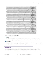
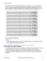
1. Choose a Cascade up or Cascade down configuration.
2. Connect cables as appropriate for the chosen configuration.
3. Select the base unit.
4. Connect the console cable.
5. Connect the AC power cord.
If you assign the base unit and non-base units with the switches powered up, you must reset
the switches for the assignments to be applied.
Identifying Cables to use with the Switch
The following table lists the required cables for a switch and cable specifications.
Required cable
Description
10/100/1GBase-T Ports
The interconnect cabling must conform to the Cat5e,
Cat6, or Cat6e
specification of the Commercial Building
Telecommunications Cabling
Standard, ANSI/TIA/EIA 568-B fitted with an RJ-45
Module Jack.
Table continues…
Identifying Cables to use with the Switch
February 2020
Installing Ethernet Routing Switch 3600 Series
31


