background image

 Notice how the output CV (magenta) is now stepped, and only changes when the audio passes 
through zero. Also, the output waveform no longer has the click at the start, since it remains at 
zero until the frst zero-crossing.
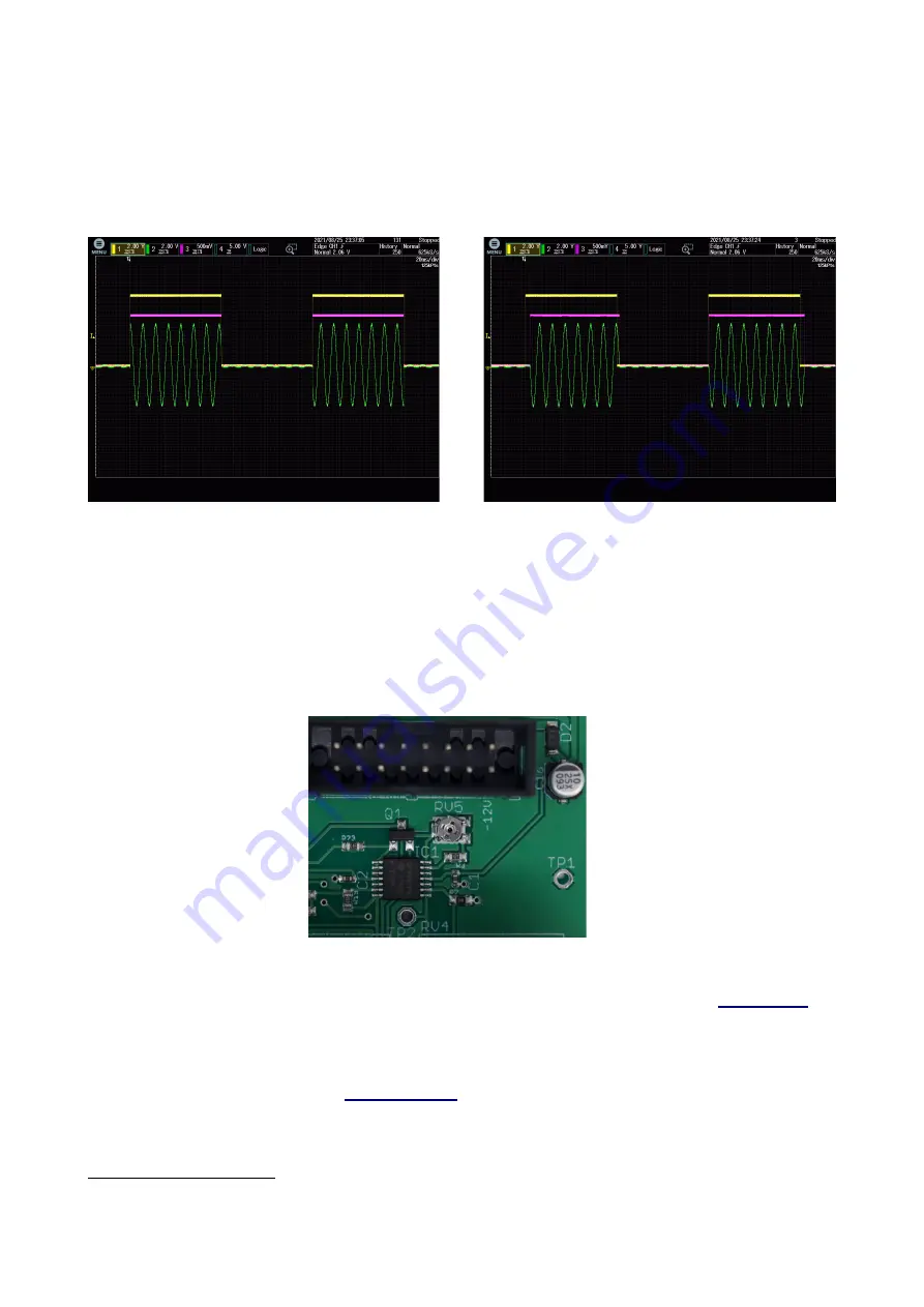
For an even more example consider the images below, now using a simple gate pulse as the CV 
input:

On the left (without zero-cross detection), note the random clicks that will occur at the start and 
end of each burst. On the right (with zero-cross detection), note how each burst begins and ends 
cleanly at zero.

Calibration

A trim pot (marked RV5) on the PCB allows for adjusting the VCA gain. Persephone is factory-
calibrated so that the module gives unity gain with Bias set to 10, Pre set to 0, and Post set to 10.

Where to get help

Email, forum, and social media links can be found at the bottom of every page on 

our website

2

.

Acknowledgments

Black and white photography by 

Israel Denadai

3

.

2 https://www.expert-sleepers.co.uk
3 http://israeldenadai.com.br/bw

Содержание Persephone

Страница 1: ...User Manual Revision 1 0 persephone ...

Страница 2: ...or copied only in accordance with the terms of such licence The content of this manual is furnished for informational use only is subject to change without notice and should not be construed as a commitment by Expert Sleepers Ltd Expert Sleepers Ltd assumes no responsibility or liability for any errors or inaccuracies that may appear in this document ...

Страница 3: ...s Introduction 4 Installation 4 Power requirements 4 Inputs and outputs 5 Controls 5 Signal fow 6 Audio path 6 CV path 6 Use as a regular VCA 7 Zero cross detection 7 Calibration 8 Where to get help 8 Acknowledgments 8 ...

Страница 4: ...uit engaged you can use a simple gate as the CV input without clicks The module s signal and CV paths are 100 analogue there is a little discrete logic involved in the zero cross circuitry Installation House the module in a Eurorack case of your choosing The power connector is 16 pin Doepfer standard1 If using the power cable supplied with the module the red edge of the cable is closest to the bot...

Страница 5: ...CV input CV output Audio input Secondary audio input Audio output The two CV inputs are summed similarly the two audio inputs are summed mixed The Clip LED in the centre of the panel lights when the output exceeds 10V indicating that you ve most likely left the realm of soft saturation and are heading into harsh clipping Controls In addition to the CV attenuator there is a knob for the CV Bias exp...

Страница 6: ...hat of reducing the level so it doesn t clip at the output The Asymmetry switch disables part of the circuit that linearises the behaviour of the VCA resulting in positive and negative sections of the input waveform being processed quite diferently increasing the even harmonic distortion The whole audio path is DC coupled CVpath The two CV inputs are summed one via the attenuator and passed to a S...

Страница 7: ...of the zero cross feature consider the following in which an envelope with a very fast attack is being applied to a fairly low frequency sine wave The yellow trace is the CV input the magenta is the CV output The green trace shows the module s audio output In this image the zero cross feature is not enabled Notice how the audio waveform rises extremely abruptly as the envelope opens This would be ...

Страница 8: ... that will occur at the start and end of each burst On the right with zero cross detection note how each burst begins and ends cleanly at zero Calibration A trim pot marked RV5 on the PCB allows for adjusting the VCA gain Persephone is factory calibrated so that the module gives unity gain with Bias set to 10 Pre set to 0 and Post set to 10 Wheretogethelp Email forum and social media links can be ...

Отзывы: