background image

17 


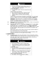
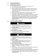
DANGER 

POTENTIAL HAZARD 

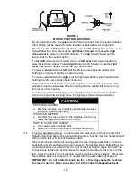
  An uncovered discharge opening will allow objects to be 

thrown in an operator’s or bystander’s direction.  Also, 
contact with the blade could occur. 

WHAT CAN HAPPEN 

  Thrown objects or blade contact can cause serious injury 

or death. 

HOW TO AVOID THE HAZARD 

  Never operate the mower with the discharge deflector 

raised, removed, or altered unless there is a grass 
collection system or mulch kit in place and working 
properly. 


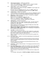
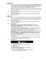
The PTO clutch push-pull switch engages the cutting blades.  Be sure that 

all


persons are 

clear

 of mower deck and discharge area 

before engaging

 PTO. 

   IMPORTANT: Operator must be in seat before the PTO can be engaged. 


Set throttle to "midway" position.  Pull outward on the switch to the “ROTATE” 
position.  Accelerate to full throttle to begin mowing. 

 3.3.5 

Stopping 

PTO: Set the throttle to the “midway” position.  Push in on the switch to 

the “STOP” position stopping the PTO. 

 3.3.6 

Stopping 

Engine: Bring unit to a 

full stop

.  

Disengage

 the PTO, 

move motion 

control levers out

 to the 

neutral lock

 position and 

engage parking brake


Before stopping the engine, place the throttle control 

midway

 between the “slow” 

and “fast” positions.  Allow the engine to run a minimum of 15 seconds; then 
stop the engine. 


Rotate ignition switch to “OFF” position.  Remove the key to prevent children or 
other unauthorized persons from starting engine. 


Close fuel shut-off valve when machine will not be used for a few days, when 
transporting, and when the unit is parked inside a building. 

 3.4 

TRANSPORTING 


3.4.1 

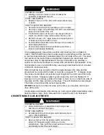
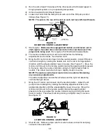
Transporting a Unit: Use a heavy-duty trailer or truck to transport the machine. 
Lock brake and block wheels. Securely fasten the machine to the trailer or truck 
with straps, chains, cable, or ropes. Be sure that the trailer or truck has all 
necessary lighting and marking as required by law.  


Secure a trailer with a safety chain. 


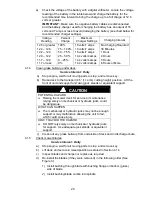
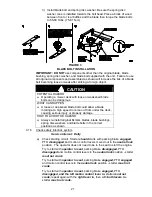
CAUTION 

POTENTIAL HAZARD 

  This unit does not have proper turn signals, lights, 

reflective markings, or a slow moving vehicle emblem.  
These items are required to drive on a public street or 
roadway. 

WHAT CAN HAPPEN 

  Driving on a street or roadway without such equipment is 

dangerous and can lead to accidents causing personal 
injury. 

  Driving on a street or roadway without such equipment 

may also be a violation of State laws and the operator 
may be subject to traffic tickets and/or fines.  

HOW TO AVOID THE HAZARD 

  Do not drive a unit on a public street or roadway. 

Содержание Lazer ZCT

Страница 1: ...For Serial Nos 600 000 Higher Part No 109 2279 Rev B ...

Страница 2: ...rom eyes and skin Never siphon by mouth IMPORTANT When the mower is used or operated on any California forest brush or grass covered land a working spark arrester must be attached to the muffler If not the operator is violating state law Section 4442 Public Resource Code To acquire a spark arrester for your unit see your Engine Service Dealer This spark ignition system complies with Canadian ICES ...

Страница 3: ...bmitting the Exmark Parts Plus order to Exmark by 3 00 p m central time the Distributor pays for the part and freight 3 Exmark being unable to ship the part and the Exmark parts order is received by 3 00 p m central time Exmark pays for the part and freight 4 If the part does not arrive overnight due to the shipper UPS the shipper pays for the freight and Exmark pays for the part The following res...

Страница 4: ...wer maintain its maximum efficiency and promote safe operation If additional information is needed or should you require trained mechanic service contact your authorized Exmark equipment dealer or distributor All Exmark equipment dealers and distributors are kept informed of the latest methods of servicing and are equipped to provide prompt and efficient service in the field or at their service st...

Страница 5: ...7 Hydrostatic Ground Drive System 12 2 8 Tires Wheels 12 2 9 Cutting Deck 12 2 10 Dimensions 12 13 2 11 Torque Requirements 13 3 OPERATION INSTRUCTIONS 3 1 Controls 13 15 3 2 Pre Start 16 3 3 Mowing 16 17 3 4 Transporting 17 18 4 MAINTENANCE ADJUSTMENTS 4 1 Periodic Maintenance 18 27 4 2 Adjustments 27 32 5 WASTE DISPOSAL 5 1 Motor Oil Disposal 33 5 2 Battery Disposal 33 6 TROUBLE SHOOTING 33 34 7...

Страница 6: ...erator s or mechanic s can not read English it is the owner s responsibility to explain this material to them 1 2 3 Do not allow operation of this machine by untrained personnel Never allow children teenagers or people unfamiliar with these instructions to use the mower Local regulations may restrict the age of the operator 1 2 4 Avoid mowing while people especially children or pets are nearby Kee...

Страница 7: ...an burn you others and cause property damage HOW TO AVOID THE HAZARD DO NOT smoke while refueling and stay away from an open flame or where gasoline fumes may be ignited by spark Refuel only outdoors Store gasoline in an approved container and keep it out of the reach of children Add fuel before starting the engine Never remove the cap of the fuel tank or add fuel when engine is running or when th...

Страница 8: ...e then refuel such equipment on a truck or trailer from a portable container rather than from a gasoline dispenser nozzle If a gasoline dispenser nozzle must be used keep the nozzle in contact with the rim of the fuel tank or container opening at all times until fueling is complete WARNING POTENTIAL HAZARD Gasoline vapor can collect inside enclosed trailers and may be ignited by electrical sparks ...

Страница 9: ...aintain in working order a spark arrester before using equipment on forest covered grass covered or brush covered unimproved land WARNING POTENTIAL HAZARD Hands feet hair clothing or accessories can become entangled in rotating parts WHAT CAN HAPPEN Contact with rotating parts can cause traumatic amputation or severe lacerations HOW TO AVOID THE HAZARD Do not operate the machine without guards shi...

Страница 10: ...rogressively greater care is needed as the slope increases Always avoid sudden starting or stopping on a slope If tires lose traction disengage the blades and proceed slowly off the slope Avoid sudden starts when mowing uphill Mower may tip backwards Be aware that loss of traction may occur going downhill Weight transfer to the front wheels may cause drive wheels to slip and cause loss of braking ...

Страница 11: ...ards switches and other devices in place and in proper working condition 1 4 9 DO NOT change the engine governor settings or overspeed the engine Operating an engine at excessive speed may increase the hazard of personal injury 1 4 10 Disengage PTO before starting engine 1 4 11 Start the engine carefully with feet well away from the blades 1 4 12 Keep hands feet and clothing away from rotating par...

Страница 12: ...ys without use 1 5 3 Allowing batteries to stand for an extended period of time without recharging them will result in reduced performance and service life To preserve optimum battery performance and life recharge batteries in storage when the open circuit voltage drops to 12 4 volts Note To prevent damage due to freezing battery should be fully charged before putting away for winter storage 1 5 4...

Страница 13: ...and shutting off the engine before performing any work on the hydraulic system 1 6 SAFETY SIGNS 1 6 1 Keep all safety signs legible Remove all grease dirt and debris from safety signs and instructional labels 1 6 2 Safety signs must be replaced if they are missing or illegible 1 6 3 When new components are installed be sure that current safety signs are affixed to the replaced components 1 6 4 New...

Страница 14: ...of Mower Deck PART NO 1 513746 LOCATION On Engine Blower Housing PART NO 1 523552 LOCATION Top of Hydraulic Reservoir PART NO 98 5954 LOCATION Under Mower Deck Belt Shield s PART NO 103 2644 LOCATION Top of Hydraulic Reservoir PART NO 107 2102 LOCATION RH Inside Surface of Upper Roll bar PART NO 109 1196 LOCATION Top Front of RH Tank PART NO 103 4892 LOCATION Right of Throttle Control on RH Tank P...

Страница 15: ...dle 1500 RPM 2 3 FUEL SYSTEM 2 3 1 Capacity 5 8 gal 21 9 L PART NO 103 7491 LOCATION On Top LH Side of Mower Deck PART NO 1 513748 LOCATION Bottom of Floorpan PART NO 107 2112 LOCATION Top Center of Floorpan PART NO 103 9116 LOCATION Bottom of Back Side of Seat PART NO 1 653147 LOCATION Lefthand Side of Cutting Height Adjustment Plate PART NO 103 9287 LOCATION Left of Center on Mower Deck Under Fl...

Страница 16: ...by varying the position of the levers relative to each other Moving motion control levers outward in slots locks the drive system in neutral Motion control levers are adjustable to two heights 2 5 2 PTO Switch Engages electric clutch to drive belt which engages mower blades 2 5 3 Parking Brake Lever Engages parking brake 2 5 4 Deck Height Adjustment Lever Sets cutting height to desired position 2 ...

Страница 17: ... 3 cm 18 00 in 45 7 cm 20 50 in 52 1 cm 2 9 4 Blade Spindles solid steel spindles with 1 2 54 cm I D bearings 2 9 5 Deck Drive Electric clutch mounted on vertical engine shaft Blades are driven by one B Section belt w self tensioning idler direct from the engine 2 9 6 Deck Full floating deck is attached to out front support frame Maximum turf protection is provided anti scalp rollers 48 Decks Qty ...

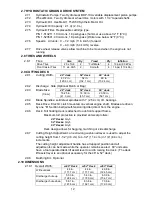
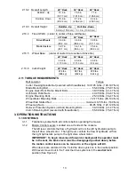
Страница 18: ...s 40 45 ft lbs 54 61 N m Engine Mounting Bolts 25 30 ft lbs 34 41 N m Wheel Motor Mounting Bolts 72 77 ft lbs 98 104 N m Wheel Hub Slotted Nut minimum 125 ft lbs 169 N m Wheel Lug Nuts 90 95 ft lbs 122 129 N m Rollover Protection System roll bar Mounting Bolts 30 35 ft lbs 41 47 N m Clutch Retaining Bolt secured with threadlocker 55 60 ft lbs 75 81 N m 3 OPERATION INSTRUCTIONS 3 1 CONTROLS 3 1 1 F...

Страница 19: ...o turn to the left while backing move the left lever forward toward neutral To turn to the right while backing move the right lever forward toward neutral CAUTION POTENTIAL HAZARD Machine can spin very rapidly by positioning one lever too much ahead of the other WHAT CAN HAPPEN Operator may lose control of the machine which may cause damage to the machine or injury HOW TO AVOID THE HAZARD Use caut...

Страница 20: ...ure in this position Brake must be engaged motion control levers out neutral lock position and PTO switch OFF to start engine It is not necessary for the operator to be in the seat to start the engine 3 1 9 Hour Meter Located on the right tank The hour meter is connected to a pressure switch installed in the engine block and it records the number of hours that the engine has run If ignition switch...

Страница 21: ... fuel shut off valve is located under the seat in the fuel line between the left fuel tank and the engine 3 3 3 Starting Engine Brake must be engaged the PTO switch disengaged and the motion control levers out neutral lock position The operator does not need to be in the seat to start the engine On a cold engine place the throttle midway between the SLOW and FAST positions and place the choke to t...

Страница 22: ...throttle control midway between the slow and fast positions Allow the engine to run a minimum of 15 seconds then stop the engine Rotate ignition switch to OFF position Remove the key to prevent children or other unauthorized persons from starting engine Close fuel shut off valve when machine will not be used for a few days when transporting and when the unit is parked inside a building 3 4 TRANSPO...

Страница 23: ...nit starts to tip backward If it is not possible to use one full width ramp use enough individual ramps to simulate a full width continuous ramp Ramp should be long enough so that the angles between the ramp and the ground and the ramp and the trailer or truck do not exceed 15 A steeper angle may cause mower deck components to get caught as the unit moves from ramp to trailer or truck Steeper angl...

Страница 24: ...LOW or ADD mark on the dipstick or over the FULL mark 4 1 2 Clean engine air cooling system Service Interval Daily or more often in dry conditions CAUTION POTENTIAL HAZARD Excessive debris can cause the engine and hydraulic system to overheat WHAT CAN HAPPEN Excessive debris around the engine cooling air intake and inside of the pump compartment can create a fire hazard HOW TO AVOID THE HAZARD Cle...

Страница 25: ...ll moving parts to stop and remove key b Raise deck to the transport 4 5 11 4cm cutting height position Lift the front of unit and support unit using jack stands or equivalent support CAUTION POTENTIAL HAZARD Raising the mower deck for service or maintenance relying solely on mechanical or hydraulic jacks could be dangerous WHAT CAN HAPPEN The mechanical or hydraulic jacks may not be enough suppor...

Страница 26: ...causing serious injury or property damage HOW TO AVOID THE HAZARD Always re install original Exmark blades blade bushings spring disc washers and blade bolts in the correct positions as shown 4 1 6 Check safety interlock system Service Interval Daily a Check starting circuit Starter should crank with parking brake engaged PTO disengaged and motion control levers moved out in the neutral lock posit...

Страница 27: ...ice Interval Daily a Stop engine wait for all moving parts to stop and remove key b Visually inspect machine for any loose hardware or any other possible problem Tighten hardware or correct the problem before operating 4 1 9 Service air cleaner Service Interval See Engine Owner s Manual a Stop engine wait for all moving parts to stop and remove key b See Engine Owner s Manual for cleaning instruct...

Страница 28: ...essures Service Interval 40 hrs a Stop engine wait for all moving parts to stop and remove key b Check tire pressure in all four tires c Inflate caster tires to 16 psi 1100 kPa d Inflate drive tires to 13 psi 90 kPa NOTE Do not add any type of tire liner or foam fill material to the tires Excessive loads created by foam filled tires may cause failures to the hydro drive system frame and other comp...

Страница 29: ...l from caster fork Remove seal guards from the wheel hub c Remove one of the spacer nuts from the axle assembly in the caster wheel Note that thread locking adhesive has been applied to lock the spacer nuts to the axle Remove the axle with the other spacer nut still assembled to it from the wheel assembly d Pry out seals and inspect bearings for wear or damage and replace if necessary e Pack the b...

Страница 30: ...c Lubricate switch actuator rod with spray type lubricant or light oil 4 1 17 Lubricate brake handle pivot Service Interval 160 hrs a Stop engine wait for all moving parts to stop and remove key b Lubricate bronze bushings on brake handle pivot with a spray type lubricant or light oil 4 1 18 Lubricate brake rod bushings Service Interval 160 hrs a Stop engine wait for all moving parts to stop and r...

Страница 31: ...the filter adapter then tighten the filter an additional 2 3 to 3 4 turn e Fill reservoir as stated in Section 4 1 10 f Raise the rear of machine up and support with jack stands or equivalent support just high enough to allow drive wheels to turn freely g Start engine and move throttle control ahead to full throttle position Move the speed control levers to the full speed and run for several minut...

Страница 32: ...ocations a Between the cutter housing spindle and bearings b Between the cutter housing spindle and sheave c Under top cutter housing bearing guard 4 1 28 Dielectric grease is used on all blade type electrical connections to prevent corrosion and loss of contact 4 2 ADJUSTMENTS IMPORTANT Disengage PTO shut off engine wait for all moving parts to stop and remove key before servicing cleaning or mak...

Страница 33: ...f of the two large deck lift springs by loosening the nuts at the front of each spring See Figure 7 f Lower the deck to the 1 1 2 3 8 cm height position Place two 1 5 16 3 3 cm thick blocks under the rear edge of the cutting deck skirt one on each side of the cutting deck Place a 1 1 8 2 9 cm block under the center front edge but not under the anti scalp roller brackets g Loosen the two 2 bottom c...

Страница 34: ...es off the seat with brake disengaged or PTO engaged but will continue to run with operator in seat a slight shift in weight should not shut machine off Normal adjustment is when length of spring is 2 09 5 3 cm with seat up NOTE To prevent rough ground cut outs the unit is equipped with a time delayed seat switch When the operator raises off the seat with either the brake disengaged or the PTO eng...

Страница 35: ... Figure 8 or 9 g Tighten the jam nuts loosened in step d FIGURE 8 TYPE A PARK BRAKE ADJUSTMENT FIGURE 9 TYPE B PARK BRAKE ADJUSTMENT 4 2 7 Adjust Throttle Lever Tension a Stop engine wait for all moving parts to stop and remove key b Tension in throttle lever can be adjusted by adjusting the tightness of the lever pivot bolt which is located under the console See Figure 10 FIGURE 10 THROTTLE TENSI...

Страница 36: ...opposite side of unit 4 2 10 Motion control linkage adjustment WARNING POTENTIAL HAZARD Engine must be running and drive wheels must be turning so motion control adjustment can be performed WHAT CAN HAPPEN Contact with moving parts or hot surfaces may cause personal injury HOW TO AVOID THE HAZARD Keep fingers hands and clothing clear of rotating components and hot surfaces CAUTION POTENTIAL HAZARD...

Страница 37: ...th by rotating the double nuts on the rod in the appropriate direction until the wheels slightly creep in reverse See Figure 11 Move the motion control lever to the reverse position and while applying slight pressure to the lever allow the reverse indicator spring to bring the levers back to neutral The wheel must stop turning or slightly creep in reverse NOTE The motion control lever needs to be ...

Страница 38: ...S LEFT OR RIGHT W LEVERS FULLY FORWARD a Refer to Tracking Adjustment Section 4 1 3 b Check air pressure in tires 13 psi drive 16 psi pneumatic casters c Check reverse indicator and motion control linkage adjustment See Section 4 2 9 and 4 2 10 6 2 MOWER CUTS UNEVENLY a Check air pressure in tires 13 psi drive 16 psi pneumatic casters A more uniform cutting height may be obtained with higher tire ...

Страница 39: ...rator safety mechanisms be connected and in proper operating condition prior to mower use When a problem occurs do not overlook the simple causes For example starting problems could be caused by an empty fuel tank The following table lists some of the common causes of trouble Do not attempt to service or replace major items or any items that call for special timing of adjustments procedures such a...

Страница 40: ...35 7 BRIGGS STRATTON ELECTRICAL DIAGRAM ...

Страница 41: ...36 8 HYDRAULIC DIAGRAM ...

Страница 42: ...sfied with the Service Dealer s analysis or with the assistance provided contact us at Exmark Customer Service Department The Exmark Warranty Company 2101 Ashland Avenue Beatrice NE 68310 402 223 6375 or service exmark com Owner s Responsibilities The Exmark turf equipment including any defective part must be returned to an authorized Exmark service dealer within the warranty period This warranty ...

Страница 43: ...t as required maintenance in the written instructions must be warranted for the warranty period of two years If any such part fails during the period of warranty coverage it must be repaired or replaced by Exmark Manufacturing Company Any such part repaired or replaced under the warranty must be warranted for a time not less than the remaining warranty period B Any warranted part that is scheduled...

Страница 44: ... 39 NOTES ...

Страница 45: ... 40 NOTES ...

Страница 46: ... 41 SERVICE RECORD Date Description of Work Done Service Done By ...

Страница 47: ... 42 ...

Страница 48: ...AC QUICK DISPOSAL SYSTEM WALK BEHIND ACCESSORIES GRASS CATCHER MICRO MULCH SYSTEM STEERABLE SULKY SULKY HITCH KIT TURF STRIPER STANDON WARNING The engine exhaust from this product contains chemicals known to the State of California to cause cancer birth defects or other reproductive harm 2004 2005 EXMARK MFG CO INC PART NO 109 2279 Rev B INDUSTRIAL PARK BOX 808 402 223 6300 BEATRICE NE 68310 FAX 4...

Отзывы: