background image

Communicating Through TCP/IP over Telnet

342

IQS-600

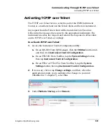
Executing SCPI Commands Over Telnet

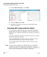
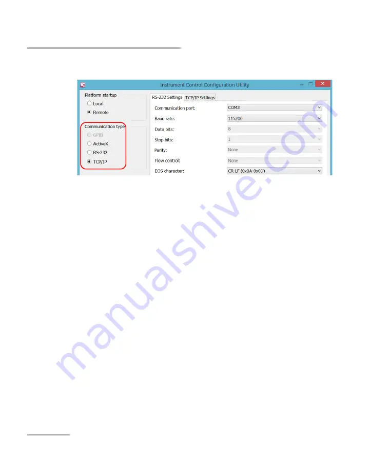
4.

Under 

Communication Type

,


select 

TCP/IP

.

5.

Click or tap 

Apply

, and then 

OK

.

6.

Depending on the unit you are using, restart either IQS Manager, 
ToolBox, or ToolBox X.

Executing SCPI Commands Over Telnet

You can remotely control the modules by executing SCPI commands 
through TCP/IP over Telnet. The commands are sent remotely from the 
Telnet client (on a computer) to the Telnet server (in this case, the IQS or 
FTB unit).

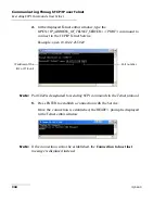
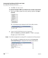
To execute a single SCPI command, you can type or paste the command 
directly in the Telnet editor window.

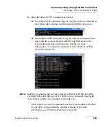
To execute multiple SCPI commands (script), you must enclose them 
within a BEGIN and END block in the Telnet editor window.

You can connect from a remote Windows client or a Linux (or Unix) 
remote client.

Note:

The Telnet client is available on the FTB-500, FTB-2 Pro, and IQS-600 
controller if you intend to use these units as computers to connect to a 
Telnet server. However, on an FTB-2, the Telnet client is not available. You 
must use the PuTTY application to establish communication.

Содержание IQS-600 Series

Страница 1: ...User Guide Integrated Qualification System IQS 600...

Страница 2: ...any infringements of patents or other rights of third parties that may result from its use No license is granted by implication or otherwise under any patent rights of EXFO EXFO s Commerce And Governm...

Страница 3: ...and Expansion Units in a Rackmount 22 Connecting One or More Expansion Units to a Controller Unit 26 Inserting and Removing Test Modules 30 Safeguarding Units with the Interlock 36 Turning the Integr...

Страница 4: ...ssing Current Modules 99 Accessing Integrated Applications 102 Working on Test Results Offline Mode 103 Creating an Integrated Data Display 104 Viewing PDF Files 106 Locating Units 107 Accessing Utili...

Страница 5: ...Replacing the Fuse 214 Managing Windows Updates 214 Recycling and Disposal Applies to European Union Only 216 10 Troubleshooting 217 Solving Common Problems 217 Restoring Your Controller Unit to Norma...

Страница 6: ...Properties and Events 329 ActiveX COM DCOM Quick Reference 330 Properties 331 Events 338 F Communicating Through TCP IP over Telnet 339 Introducing TCP IP over Telnet 339 Features 340 Activating TCP...

Страница 7: ...FO Inc makes reasonable efforts to ensure compliance to the applicable standards The limits set by these standards are designed to provide reasonable protection against harmful interference when the e...

Страница 8: ...of conformity for your product is available on our website at www exfo com Refer to the product s page on the Web site for details IMPORTANT Use of shielded remote I O cables with properly grounded sh...

Страница 9: ...ific order all the high speed units first followed by all the standard units When several high speed units are linked the high speed capability is available for the first three high speed units only H...

Страница 10: ...have previously purchased any For a complete list of supported modules go to the EXFO Web site The IQS 600 Integrated Qualification System runs under Microsoft Windows 8 1 Pro with the IQS Manager sof...

Страница 11: ...5P HS controller unit is where you perform basic operations such as turning your unit on or off consulting LED indicators and using data related peripherals for example the USB ports Module connector...

Страница 12: ...outlets and connectors to link expansion units to your controller unit Control Out port Interlock ground terminals 2 Audio ports 3 USB ports 4 Serial port Ethernet port 2 Parallel printer port AC soc...

Страница 13: ...IQS 610P HS controller unit is where you perform basic operations such as turning your unit on or off consulting LED indicators and using data related peripherals for example the USB ports and the DV...

Страница 14: ...outlets and connectors to link expansion units to your controller unit Parallel printer port PS 2 keyboard port BNC synchronization port Trigger output Trigger input Ethernet ports 2 Serial port Audi...

Страница 15: ...ons such as turning your unit on or off and consulting LED indicators The back of the IQS 610E HS expansion unit is where you find the power outlets and connectors to link your expansion units to your...

Страница 16: ...or through a chain Lock LED When lit the unit is in Lockout mode you can only disable this mode by sending the corresponding remote command Interlock LED When lit it indicates that the Interlock is o...

Страница 17: ...out mode you can only disable this mode by sending the corresponding remote command Alarm indicator LED When lit on the controller unit it indicates a problem When lit on an expansion unit the latter...

Страница 18: ...lications brought by the Program Switcher button It is the equivalent of pressing the Tab key on a keyboard Enter This button allows you to select the highlighted element on the screen It is the equiv...

Страница 19: ...grated Qualification System Synchronization Ports The synchronization and trigger ports are not currently supported by the IQS 600 Integrated Qualification System The ports located at the back of the...

Страница 20: ...RAID 1 hard disk drive configuration provides a live backup of all test data RAID 1 dual hard disk drives are installed at the factory They cannot be installed in the field To retrofit your IQS 600 w...

Страница 21: ...ious injury Do not proceed unless you understand and meet the required conditions CAUTION Indicates a potentially hazardous situation which if not avoided may result in minor or moderate injury Do not...

Страница 22: ......

Страница 23: ...are protected at all times WARNING The use of controls adjustments and procedures namely for operation and maintenance other than those specified herein may result in hazardous radiation exposure or i...

Страница 24: ...ord without a protective conductor Before turning on the unit connect all grounding terminals and extension cords to a protective ground via a ground socket Any interruption of the protective groundin...

Страница 25: ...move unit covers during operation Operation of any electrical instrument around flammable gases or fumes constitutes a major safety hazard To avoid electrical shock do not operate the unit if any part...

Страница 26: ...tion degree 2 Overvoltage category II Measurement category Not rated for measurement categories II III or IV Input powerb b Not exceeding 10 of the nominal voltage unit 100 240 V 50 60 Hz 550 VA CAUTI...

Страница 27: ...it One or more of the following symbols may also appear on your unit Symbol Meaning Direct current Alternating current The unit is equipped with an earth ground terminal The unit is equipped with a pr...

Страница 28: ......

Страница 29: ...the angle of your IQS 605P HS controller unit in order to have a better view of the screen Use the stand located under the front part of the unit and pull it down and forward CAUTION If you are using...

Страница 30: ...learance 25 mm 1 in of side clearance left and right Note There is no need to leave an empty slot between units when you stack them one on top of the other inside a rackmount Install your controller a...

Страница 31: ...s in a Rackmount To prepare your unit for rackmount use 1 Ensure that your unit is turned off 2 Remove the bumpers of your controller unit by unscrewing the top and bottom screws CAUTION You should re...

Страница 32: ...ntroller and Expansion Units in a Rackmount 3 Assemble the rackmount kit panels using the supplied screws The screws used for the bumpers will not work to secure the rackmount kit panels You must use...

Страница 33: ...ed unit into the cabinet as shown below and secure it in place using the hardware supplied with the rack 5 Repeat steps 1 through 3 for each unit being installed in the rackmount If you want to move a...

Страница 34: ...ee Installing Your Controller and Expansion Units in a Rackmount on page 22 for instructions Note As your expansion units are daisy chained the position is indicated by a number displayed on the unit...

Страница 35: ...onnect an Expansion Unit to a Controller Unit 1 Connect the provided cable to the EXFO Bus Out port located at the back of your controller unit IMPORTANT To ensure that your cable is properly connecte...

Страница 36: ...n System 28 IQS 600 Connecting One or More Expansion Units to a Controller Unit 2 Connect the other end of the cable to the EXFO Bus In port located at the back of your expansion unit EXFO expansion u...

Страница 37: ...g One or More Expansion Units to a Controller Unit 3 To connect additional IQS 610E HS expansion units to your system use another cable to connect the EXFO Bus Out port of the first unit to the EXFO B...

Страница 38: ...es Inserting and Removing Test Modules CAUTION Never insert or remove a module while the controller unit and its expansion units are turned on This will result in immediate and irreparable damage to b...

Страница 39: ...l your units 2 Remove the protective cover from the desired unused module slot 2a Pull the retaining screw knob firmly towards you and release the bottom of the cover 2b Gently pull the top of the pro...

Страница 40: ...ush the module all the way to the back of the slot until the retaining screw makes contact with the unit casing 6 While applying slight pressure to the module turn the retaining screw knob located at...

Страница 41: ...your module Note You can insert IQ modules into your controller or expansion unit the IQS Manager software will recognize them However the IQS 600 locking mechanism retaining screw will not work for...

Страница 42: ...by pushing the retaining screw knob Since IQ modules do not have retaining screw knobs to help you remove them EXFO provided you with a special tool to facilitate the operation CAUTION Pulling out a...

Страница 43: ...moving Test Modules To remove IQ modules 1 Slide the tool s end between the module front panel and the unit 2 Using the bumper as the pivot point push down the tool to release the module 3 Pull the mo...

Страница 44: ...r ups If your module is equipped with an interlock system you might have to link the terminals located at the back of your IQS 610P HS controller unit with the provided connectors You can connect your...

Страница 45: ...any voltage to the interlock terminals since only a mechanical contact is needed For more information about the type of interlock system to use with the module you are working with refer to the corre...

Страница 46: ...on units use a proper starting sequence First turn on the expansion units and then turn on your IQS 600 controller unit Failure to use proper starting sequence may lead to malfunction Note If you have...

Страница 47: ...documentation for important safety information and to read and accept the EULA related to your unit and instruments Note To be able to work with the unit you must accept all the EULA from Microsoft an...

Страница 48: ...with Your Integrated Qualification System 40 IQS 600 Configuring Your Unit At First Startup 4 When the EXFO wizard is displayed follow the on screen instructions 5 Click Finish to close the wizard an...

Страница 49: ...y want to visit Microsoft Web site for tutorials as well as detailed information on the features and concepts brought by this operating system One of the new features is the use of touchscreen gesture...

Страница 50: ...our IQS 605P unit Tap and double tap Equivalent of a click and double click with a mouse Swipe right To return to the last used application From the left edge of the screen swipe towards the right Swi...

Страница 51: ...cations inside IQS Manager or the Windows on screen keyboard for applications inside IQS Manager or in Windows Note The Windows on screen keyboard supports multilingual features and functions accordin...

Страница 52: ...tion tab then the System tab 2 Click the Settings button 3 Under Keyboard select the Use On Screen Keyboard option box The next time you need to enter data a keyboard appears and you can type using yo...

Страница 53: ...rds To select the keyboard type 1 In the main window select the Utilities function tab then the System tab 2 Click the Settings button 3 Under Keyboard use the up and down arrow buttons to select your...

Страница 54: ...y that the most recent Update Manager application is installed on your unit When updates are available for an application you will need to download them from Internet either directly on your unit or o...

Страница 55: ...tallation files to this USB key 2 If it is not already done turn on your unit 3 Exit IQS Manager and the modules applications 4 If you want to install Update Manager using the USB key disconnect it fr...

Страница 56: ...or update applications using the USB key disconnect it from the computer and connect it to one of the USB ports of your unit 5 Copy the installation files from the USB key to the folder containing th...

Страница 57: ...e or platform serial number depending on whether the software options were purchased for a module or the platform Customer s name Customer s company name Customer s phone number Customer s e mail addr...

Страница 58: ...the options for your unit 1 Connect a USB memory key to one of the USB ports of your computer 2 Copy the key file to the USB memory key 3 Disconnect the USB key from the computer and connect it to yo...

Страница 59: ...button to locate the key file that you want to use 7 Click Activate The option indicator will turn into a green check mark to confirm that the option is now active 8 Click OK to close the confirmatio...

Страница 60: ...ftware options for your module 1 Connect a USB memory key to one of the USB ports of your computer 2 Copy the key file to the USB memory key 3 Disconnect the USB key from the computer and connect it t...

Страница 61: ...onfirm that the option is now active Note You can see the supported options for the module in the Options list 8 Click OK to close the confirmation message and then Close to exit Note At this point if...

Страница 62: ...cally with Windows 8 1 Pro However if you want to start it automatically with IQS Manager see Selecting the Startup Interface on page 84 To access IQS Manager when in the Windows environment Click the...

Страница 63: ...tely shut down the IQS 600 controller unit 3 Click OK to confirm your choice or Cancel to return to IQS Manager Note Expansion units are shut down manually by pressing on the On Off button located on...

Страница 64: ...alification System National Instruments LabVIEW software and the corresponding patches EXFO LabVIEW drivers including demo applications to help you get started with the drivers You can find the LabVIE...

Страница 65: ...plorer tile 2b Locate the autorun exe file then double click on it to start the installation procedure and follow the on screen instructions You should keep the default names and paths suggested by th...

Страница 66: ...the taskbar under Windows 8 1 Pro Note To access the File Explorer on your unit from the front panel press the button to show the taskbar IQS 605P units From the lower left corner of the screen click...

Страница 67: ...itor Connect your monitor to the standard computer connector located at the back of the unit Note Use the Windows Control Panel to configure the display settings of your external monitor Note You cann...

Страница 68: ...the front part of your units This would press on the front opening thus preventing you from inserting or removing modules correctly Ensure that the monitor is at least 8 inches away from the front of...

Страница 69: ...Qualification System can be used with either a USB or a PS 2 keyboard To connect a keyboard to the unit Use any of the USB ports located both at the front and back of the unit OR Use the PS 2 keyboar...

Страница 70: ...the unit Use any of the USB ports located both at the front and back of the unit OR Use the PS 2 mouse port located at the back of the unit Your USB mouse is automatically recognized and immediately...

Страница 71: ...tem 63 Connecting a Tape CD or DVD Player Connecting a Tape CD or DVD Player Your IQS 600 Integrated Qualification System can be used with an external tape CD or DVD player To connect a tape CD or DVD...

Страница 72: ...Connecting a Headset or a Speaker Connecting a Headset or a Speaker Your IQS 600 Integrated Qualification System can be used with either a headset or speaker To connect a headset or speaker to the uni...

Страница 73: ...ted Qualification System 65 Connecting a Microphone Connecting a Microphone Your IQS 600 Integrated Qualification System can be used with a microphone To connect a microphone to the unit Use the micro...

Страница 74: ...ification System can be used with a printer To connect a printer to the unit Use any of the USB ports located both at the front and back of the unit OR Use the parallel port located at the back of the...

Страница 75: ...ilable depending on the version of the software you are using The IQS 605P HS controller unit comes equipped with a stylus to use with your touchscreen The stylus is located in the lower right corner...

Страница 76: ...pps section under UPDD select Calibrate 4 Follow the calibration procedure described on the corresponding tab Adjusting Microphone and Speaker Volume Different working environments call for different...

Страница 77: ...3 Move the slider until the sound level is to your liking Note You can also access the sound level slider by using the icon from the taskbar Changing the Backlight Level IQS 605P HS The backlight has...

Страница 78: ...and you do not want any LED or light activity that could compromise your test results Note The backlight does not automatically turn off You must adjust it as explained above To deactivate the LED di...

Страница 79: ...ange the interface language the corresponding keyboard is automatically added to the list of available keyboards You can then enter text in a specific language either on screen or using a hardware key...

Страница 80: ...72 IQS 600 Selecting the Language of Operation 3 Select the desired language from the list Note If the language you want is not in the list of available languages you must install the corresponding la...

Страница 81: ...ion System Integrated Qualification System 73 Selecting the Language of Operation 5 If you want to select another keyboard layout than the one that has been added by default proceed as follows 5a Unde...

Страница 82: ...Setting Up Your Integrated Qualification System 74 IQS 600 Selecting the Language of Operation 5b Select the desired keyboard layout then click Add...

Страница 83: ...age of Operation 6 Under Windows display language click Make this the primary language 7 When the application prompts you to log off select Log off now 8 Once you see the lock screen log in your user...

Страница 84: ...0 Selecting the Language of Operation To download language packs 1 Ensure that your unit has access to the Internet 2 From the Windows Desktop right click on the Start button then select Control Panel...

Страница 85: ...ication System Integrated Qualification System 77 Selecting the Language of Operation 4 Click Add a language 5 Browse the list of languages and then select the one that you want to use 6 Click Open to...

Страница 86: ...Setting Up Your Integrated Qualification System 78 IQS 600 Selecting the Language of Operation 7 Select the desired sub language and then click Add...

Страница 87: ...Setting Up Your Integrated Qualification System Integrated Qualification System 79 Selecting the Language of Operation 8 Select the desired language from the list 9 Click Options...

Страница 88: ...tion may take a few minutes 12 When the installation is complete restart your unit To switch from one input language to another 1 From the taskbar click the language code to display the list of availa...

Страница 89: ...e The time can be expressed with a 12 or 24 hour notation You can modify the way dates and time are displayed if the default values do not suit your needs For information on how to adjust the date the...

Страница 90: ...egrated Qualification System 82 IQS 600 Setting Date and Time Formats 3 Refine the settings according to your needs 4 Click Apply to confirm and then OK to close the window The values are taken into a...

Страница 91: ...ow When saving results the unit also saves the corresponding date and time For information on how to modify the format in which the date and time are displayed see Setting Date and Time Formats on pag...

Страница 92: ...e unit on To select the startup interface 1 Select the Utilities function tab and then select the System tab 2 Click the Settings button 3 Select the Launch IQS Manager on Startup check box 4 Click Ap...

Страница 93: ...atically start IQS Manager in Administrator level mode If you want to set passwords for other user types refer to the Windows online help under Passwords Power User and Standard User levels have limit...

Страница 94: ...u want the users to access by checking the corresponding boxes Hardware Configuration to rename hardware IQS Manager Setup to change items in the Settings section of the Utilities function tab Save Sy...

Страница 95: ...e every user protect their account with a password For security reasons by default the automatic logon is not enabled Once it is enabled if you want to modify the password of the user account for whic...

Страница 96: ...ically log on to Windows upon startup 1 Start Windows 2 On the taskbar of the computer click the start button then under Windows System select Run 3 In the Run box type control userpasswords2 then sel...

Страница 97: ...t menu in step 1 If you normally type a password to log on type your password in both the Password and Confirm Password boxes Otherwise leave these boxes blank 6 Select OK Auto logon now allows anyone...

Страница 98: ...unit and its expansion units Note Depending on your test configuration it is possible that the minimum safe value corresponds to full speed Note The specifications of the IQS modules are based on max...

Страница 99: ...ting the Fan Speed To adjust the fan speed 1 In the main window select the Utilities function tab 2 Select the Tools tab then Fan Speed Setup 3 Select the desired option 4 Click Close to save and appl...

Страница 100: ...es active modules settings under the Settings button Once a configuration is saved you can use it on any other IQS 610P HS controller unit providing you are using the same type of modules in both To s...

Страница 101: ...System 93 Saving and Opening Configurations To load a configuration 1 Select the Utilities function tab and then select the System tab 2 Click Load Configuration 3 In the list at the top of the Open...

Страница 102: ...Manager 1 Select the Utilities function tab and then select the System tab 2 Click the Settings button 3 Select the Save Configuration on Exit check box 4 Click Apply to confirm your choice then Close...

Страница 103: ...ot available in Offline mode You can change the identification of your units and modules for easier hardware management To change the identification for your unit or module 1 Select the Utilities func...

Страница 104: ...onfigure it will turn white to indicate that it is selected 4 Change the unit or module name and number as desired using the corresponding fields Click next to the field to enter your new settings 5 T...

Страница 105: ...ou can only use the Revert to Factory function if you are logged on as an Administrator level user The button is unavailable for the other user levels To revert to the factory settings 1 Select the Ut...

Страница 106: ......

Страница 107: ...Exit option on the Systems tab of the Settings dialog box the Current Modules function tab appears each time you start a new IQS Manager session The Current Modules function tab is divided into four s...

Страница 108: ...function buttons section allows you to perform s tasks on the modules currently in your system such as starting a single module application Status Bar The status bar located at the bottom of the main...

Страница 109: ...y in Remote mode and wish to revert to Local mode press on the LOCAL button on the front of your controller unit This button is ineffective if you are in Lockout mode For detailed instructions on how...

Страница 110: ...t the same time The multimodule applications allow you to control several modules of the same kind through a single interface It is particularly useful to synchronize similar modules in larger systems...

Страница 111: ...ns or tests that have already been taken This is also known as Offline mode Each module has its own tab which contains related applications It is not necessary for the module to be physically inside t...

Страница 112: ...in IQS Manager To do so select the Monitors function tab Monitor windows display basic data about modules Using a combination of resizable monitor windows allows you to create an integrated data displ...

Страница 113: ...in the chosen direction or swaps with the window currently there You can also display only one column of monitor windows instead of two by using the button located on the lower left hand corner of the...

Страница 114: ...refer to the SumatraPDF online help To view PDF files 1 From the Utilities function tab select Windows Explorer 2 Browse through the folders to find the desired PDF file 3 Double click the file 4 The...

Страница 115: ...it may become difficult to find a particular module To help you locate units click Locate Unit in the Current Modules function tab The corresponding module position display blinks for ten seconds allo...

Страница 116: ...ated on the Utilities function tab Accessing Utilities from Windows Your unit comes with free tools such as Wireshark to help you troubleshoot networks For more information refer to the online help pr...

Страница 117: ...be connected to the unit at a time Not exclusive several users can be connected to the unit at the same time sharing the same session Windows user rights Taken into account Not taken into account Pass...

Страница 118: ...g it remotely Accessing Your Unit with Remote Desktop To be able to connect to the unit using Remote Desktop you must Know the IP address of the unit and provide it in the connection settings on the c...

Страница 119: ...ictions might prevent them from communicating 2 Turn on both the computer and the unit 3 On the taskbar of the computer click the start button then under Windows Accessories select Remote Desktop Conn...

Страница 120: ...default only the accounts with administrator rights can use Remote Desktop However you can assign extra user rights to accounts with limited rights so that they can also use Remote Desktop To allow an...

Страница 121: ...y Integrated Qualification System 113 Allowing User with Limited Accounts to Use Remote Desktop 3 Under System select Allow remote access 4 Under Remote Desktop select Allow remote connections to this...

Страница 122: ...cessing your IQS 600 Remotely 114 IQS 600 Allowing User with Limited Accounts to Use Remote Desktop 6 From the Remote Desktop Users dialog box click Add 7 From the Select Users dialog box click Advanc...

Страница 123: ...grated Qualification System 115 Allowing User with Limited Accounts to Use Remote Desktop 8 Click Find Now to let the system find and display the list of users 9 Select the user to which you want to g...

Страница 124: ...of users select the user that you have just added and then click OK 11 Repeat steps 8 to 10 with all the users to which you want to grant access rights 12 From the Remote Desktop Users dialog box clic...

Страница 125: ...u may need to restart or shutdown your unit while you are controlling it remotely To restart or turn off your unit with Remote Desktop 1 Close all applications including IQS Manager 2 On the taskbar o...

Страница 126: ...nd provide it in the connection settings on the computer Know the password same for all users by default This section provides you with the basic information to control your unit with TightVNC For mor...

Страница 127: ...asswords before establishing a connection between a computer and your unit To configure the TightVNC Server 1 On the taskbar of the computer click the start button then under Tight VNC select Run Tigh...

Страница 128: ...rm the appropriate passwords Note The two passwords are independent of each other They do not have to be identical 5 Click Apply and then OK IMPORTANT Once the VNC server is installed and configured y...

Страница 129: ...you need to install it on another computer or unit download it from the TightVNC Web site Note EXFO recommends to make a shortcut on your desktop once your TightVNC Viewer is downloaded To start the...

Страница 130: ...Explorer The TightVNC server contains a small Web server When you connect to it by using your Internet search engine the Java applet for the viewer is downloaded automatically It allows you to access...

Страница 131: ...connect remotely by using a Web browser 1 From the computer Web browser enter an appropriate IP address following the example below 2 In the VNC Authentication dialog box in the Password box type you...

Страница 132: ......

Страница 133: ...requires a controller unit IQS 605P HS or IQS 610P HS to drive the instruments optical as well as Transport and Datacom Since IQS controller units are built around an Intel processor and are based on...

Страница 134: ...your own application The instruments can be controlled either locally or remotely via the following technologies The choice of a technology depends on your particular needs GPIB RS 232 ActiveX DCOM E...

Страница 135: ...ace No need for a GPIB card Allows the sharing of network resources Allows you to develop computer based applications to directly communicate with the IQS controller unit Remote GPIB IQS controller un...

Страница 136: ...Ethernet TCP IP IQS controller unit can be directly connected to a Local Area Network LAN or Wide Area Network WAN via its 10 100 1000 Base T interface No need for a GPIB card Allows the sharing of ne...

Страница 137: ...he drivers and software are installed by default Your unit can both be used as a controller or a device Should you need to reinstall the corresponding drivers and software you can do to easily through...

Страница 138: ...on the National Instrument Web site at the following location http www ni com download ni 488 2 3 1 2 4360 en and download the installation kit 2 Double click on the executable file you have download...

Страница 139: ...System for Working with GPIB 4 In the installation wizard Welcome window select Install Software Confirm that you want to proceed with the installation by clicking Yes 5 Confirm the location where the...

Страница 140: ...h GPIB 6 Confirm which items will be installed on your unit EXFO recommends that you do not change the list Click Next to continue 7 If you want to look for updates for your software you can have the...

Страница 141: ...System for Working with GPIB 8 Read the license agreement then confirm that you accept the terms click Next to continue 9 Review which items will be installed or updated then click Next to start the i...

Страница 142: ...already have a user profile at National Instruments you can use it to register your product directly from the Web Otherwise select the option to register your product without an NI profile Click Next...

Страница 143: ...fication System 135 Configuring Your Integrated Qualification System for Working with GPIB 12 Select which items you want registered Click Register to confirm your choice 13 Once the registration is c...

Страница 144: ...y connected to each GPIB bus Maximum separation of 4 m between two devices and an average separation of 2 m over the entire range bus Maximum total cable length used in the system is 20 m At least two...

Страница 145: ...he HS488 high speed protocol Complete source handshake extended capability AHE1b b AHE1 corresponds to the extended capability of AH1 defined in the IEEE 488 1 standard This extended capability is mad...

Страница 146: ...e to link it to the other unit with which you want to perform remote control For more information about your GPIB card refer to the documentation provided with it Linking Units with the Ethernet Port...

Страница 147: ...presented hereafter will help you get the best transfer rate possible Protocol GPIB control only You can use the IEEE 488 1 standard or the HS488 high speed protocol Both protocols can co exist in th...

Страница 148: ...possible bus timings are If your setup supports it select the very high speed timing to get the best performance Output unit GPIB RS 232 ActiveX and TCP IP The IQS controller unitcan return results i...

Страница 149: ...rate Often the PACKed format is also more efficient since it reduces the IQS controller unit sCPU work load no need for an internal conversion to ASCII format Note The PACKed format will only be appl...

Страница 150: ...fied without turning on your IQS 600 Integrated Qualification System and starting IQS Manager To change communication settings 1 From the Utilities function tab select Instrument Control Configuration...

Страница 151: ...ion units If Remote mode is selected all modules in your IQS controller and expansion units will be initialized upon startup so you are ready to send remote commands If you selected Local mode you can...

Страница 152: ...ontroller and expansion units can have up to four GPIB cards Default value is GPIB0 Select the check box to enable the high speed mode Bus timing in ns The selected address must not already be used by...

Страница 153: ...through TCP IP over Telnet 6 Click Apply to confirm your changes 7 To close the Communication Settings function tab click Exit To revert to default general settings 1 Click the Restore Default Setting...

Страница 154: ...Preparing for Automation 146 IQS 600 Changing Communication Settings To revert to default RS 232 settings 1 Click the Default RS 232 Settings button 2 Click Apply to confirm your changes...

Страница 155: ...th network security users groups domain management etc Basic programming skills are also required to work with DCOM For more information you can refer to the Microsoft MSDN Help feature which provides...

Страница 156: ...or access rights To set the general security parameters 1 Start Windows 2 From the main window click the System Settings button 3 Click Control Panel 4 Click System and Security Administrative Tools 5...

Страница 157: ...ing for Automation Integrated Qualification System 149 Configuring DCOM Access to Your Unit 8 In the My Computer Properties dialog box click the COM Security tab 9 Under Access Permissions click Edit...

Страница 158: ...figuring DCOM Access to Your Unit 10 In the Access Permission dialog box ensure that the Distributed COM Users group appears in the Group or user names list 11 Click OK 12 In the My Computer Propertie...

Страница 159: ...Preparing for Automation Integrated Qualification System 151 Configuring DCOM Access to Your Unit 13 Under Launch and Activation Permissions click Edit Limits...

Страница 160: ...in the Group or user names list You can now allow users to access general DCOM services on your unit You can either Add a user to the Distributed COM Users group refer to Microsoft help OR Add a user...

Страница 161: ...ication System 153 Configuring DCOM Access to Your Unit To add a user explicitly 1 In the My Computer Properties dialog box click the COM Security tab 2 Under Access Permission click Edit Limits 3 In...

Страница 162: ...tomation 154 IQS 600 Configuring DCOM Access to Your Unit 4 In the Select Users or Groups dialog box under Enter the object names to select type the name of the user to whom you want to give access ri...

Страница 163: ...has remote access permission as follows 6a In the Access Permission dialog box select the name of the new user 6b Under Permissions for new user ensure Allow is selected for Remote Access 6c Click OK...

Страница 164: ...s to Your Unit 9 In the Launch and Activation Permission dialog box click Add 10 In the Select Users or Groups dialog box under Enter the object names to select type the name of the user to whom you w...

Страница 165: ...r Unit 12 Confirm the newly added user has Remote Launch and Remote Activation permissions as follows 12a In the Launch Permission dialog box select the name of the new user 12b Under Permissions for...

Страница 166: ...ity parameters you can define the specific security parameters To customize the specific security parameters 1 From the Component Services window select Console Root Component Services Computers My Co...

Страница 167: ...Preparing for Automation Integrated Qualification System 159 Configuring DCOM Access to Your Unit 4 In the Authentication Level list select Default...

Страница 168: ...click Edit to edit the list of allowed users IMPORTANT Customizing access rights sets both remote AND local permissions As a result you will have to specify every user who must have local access to t...

Страница 169: ...Access to Your Unit 7 In the Launch and Activation Permission dialog box click Add 8 In the Select Users or Groups dialog box under Enter the object names to select type the name of the user to whom y...

Страница 170: ...ss to Your Unit 10 In the Launch and Activation Permission dialog box select a user 11 To allow this user to start and activate the IQS 600 remotely select Allow for all four permission choices 12 Rep...

Страница 171: ...he list of allowed users 16 In the Access Permission dialog box click Add IMPORTANT Customizing access rights sets both remote AND local permissions As a result you will have to specify every user who...

Страница 172: ...ccess to Your Unit 17 In the Select Users or Groups dialog box under Enter the object names to select type the name of the user to whom you want to give access permissions for remote access 18 Click O...

Страница 173: ...oices Note You can also deny connection permission for specific users 21 Repeat steps 19 and 20 for each newly added user 22 Click OK to close the Access Permission dialog box 23 Click OK to close the...

Страница 174: ...to EXFO IcSCPIAccess Class component events you need to set security parameters on the client computer To enable DCOM on the client computer 1 Start Windows on the taskbar click Start Start button und...

Страница 175: ...en select Properties 5 In the My Computer Properties dialog box click the Default Properties tab 6 Select Enable Distributed COM on this computer 7 Under Default Distributed COM Communication Properti...

Страница 176: ...ccess Permissions click Edit Limits 11 In the Access Permission dialog box ensure that for ANONYMOUS LOGON local and remote accesses are allowed If ANONYMOUS LOGON is not listed under Group or user na...

Страница 177: ...r IQS 600 using DCOM you can disable this access To disable DCOM access to your IQS 600 1 From the main window tap the System Settings button 2 Tap Control Panel 3 Tap System and Security Administrati...

Страница 178: ...ion Permissions and Access Permissions select Use Default This ensures the EXFO IcSCPIAccess Class component uses the default lists instead of the customized lists 9 Click OK 10 Restart your IQS 600 I...

Страница 179: ...elp you identify it The user controlling the module from a computer must install the dedicated application for more information on the installation refer to the application documentation The module ca...

Страница 180: ...utomation 172 IQS 600 Preparing to Control Modules with a Dedicated Application To activate or deactivate remote control 1 From the Utilities function tab select the System tab 2 Select Remote Control...

Страница 181: ...l see all the inserted modules Select the module for which you want to have a remote access Note Modules for which remote control is not supported are identified as unrecognized 4 Set the parameters S...

Страница 182: ...sponds to the test interface ID or any other relevant description 6 Click Apply to confirm your changes or OK to apply your changes and close the window Note This information will be updated the next...

Страница 183: ...u to build your own application Your application can be developed using LabVIEW Visual C NET Visual Basic or any other language that runs under Windows 8 1 Pro The present chapter gives you informatio...

Страница 184: ...tate at unit turn on Remote Front panel keys of the IQS controller unit and peripherals are not functional except for the LOCAL key and the power switch The REMOTE LED of the IQS controller unit is li...

Страница 185: ...it and peripherals are not functional except for the power button Return to Local mode only possible via commands sent from the system controller Pressing the front panel LOCAL key causes an URQ messa...

Страница 186: ...lse The RemoteState property to True 2 The remote interface message REM bus line is set to True The local lockout interface message LLO is set to True The LockoutState property to True 3 One of the fo...

Страница 187: ...controller will be lost reset of device configuration when turning on 4 The local lockout interface message LLO is set to True The LockoutState property to True 5 The Clear Lockout Set Local message...

Страница 188: ...f a First In First Out FIFO data structure Stores Data Bytes DABs and END messages Delivers messages to the parser in the order that they were received from the I O control Maximum message length unli...

Страница 189: ...sends response messages from the output queue to the controller Response messages all end with a RESPONSE MESSAGE TERMINATOR see the appendix on data types Total storage capacity only limited to the...

Страница 190: ...the most recent is removed and the Queue overflow error error 350 is added No new items will be stored into the queue until there will be room available As soon as there is data in the output queue t...

Страница 191: ...nts and get useful information on the status of the devices it controls Standard Event Status Register ESR Standard Event Status Enable Register ESE Status Byte Register STB Service Request Enable Reg...

Страница 192: ...s presented in the following table Register Read Write Clear ESR Use ESR Impossible to write Use CLS Read the register ESE Use ESE Use ESE Use ESE with a value equal to 0 At IQS Manager startup the re...

Страница 193: ...he controller will then find which device generated a SRQ its RQS bit is set and the causes of it Register Read Write Clear STB Use STB Use serial poll GPIB bus sequence that allows retrieval of the v...

Страница 194: ...Using IQS Products in an Automated Test Environment 186 IQS 600 Standard Status Data Structure...

Страница 195: ...d Common Commands For Use with ANSI IEEE Std 488 1 1987 New York 1992 Standard Commands for Programmable Instruments SCPI Volume 1 Syntax and Style Vers 1999 0 May U S A 1999 The provided commands fol...

Страница 196: ...t any branch of the command tree root intermediate node or terminal node Example If the command is SENSe 1 n CORRection COLLect ZERO and you want it to take effect on the second SENSe sensor capabilit...

Страница 197: ...be sent or the response you will receive from an instrument Do not include angled brackets in your program message Indicates that one and only one value must be selected from the available choices Exa...

Страница 198: ...rogram messages but they will not be taken into account For more information see Message Management on page 180 Mandatory to separate the different commands of a program message when more than one com...

Страница 199: ...IEEE 488 2 required commands or queries beginning with a that are part of the program message have no effect on the paths Example system version idn system error next is equivalent to system version i...

Страница 200: ...supports GPIB communication GPIB development kits are available for most of the popular commercial programming languages The IQS 600 Integrated Qualification System offers many commands permitting co...

Страница 201: ...corresponding query has not been previously sent to the instrument You must pay special attention to queries that return an indefinite ASCII response To avoid any confusion the IEEE 488 2 standard req...

Страница 202: ...the above figure the message contains three parts error number error description device dependent information Error messages ending in a negative number are SCPI based errors For more information on e...

Страница 203: ...g the communication parameters via LabVIEW provided applications or new VI you must configure the IQS 600 Integrated Qualification System for remote control For more information see the section on pre...

Страница 204: ...or IEEE 488 2 commands you can leave the slot number at its current value Parameter Active X local Active X remote RS 232 remote GPIB remote Communication type ActiveX ActiveX RS232 GPIB VISA resourc...

Страница 205: ...ice Some of the available functions by loading the necessary vi files All the vi files related to an instrument are presented in the same folder By default they are found under the location where your...

Страница 206: ...use the instrument easily In fact the application performs the necessary calls to the instrument s drivers so it is transparent to the user The application state called State Machine changes whenever...

Страница 207: ...ine after the user has clicked on the button allowing you to set the source state from the Front Panel When the State Machine changes to SetSourceState the application calls Instrument2600bTest_SetSou...

Страница 208: ...t IQS Manager and ensure that all the remote control parameters are set correctly 2 Open the desired Getting Started application and run it from LabVIEW 3 From the application s Front Panel set the co...

Страница 209: ...ication System 201 Using the EXFO Getting Started Applications 6 When you are finished select Close to end the communication 7 Close LabVIEW IMPORTANT To avoid losing the original version of the Getti...

Страница 210: ...Files National Instruments LabVIEW 6 instr lib EXFO from the LabVIEW function palettes Each icon of the EXFO palette corresponds to a set of drivers that allow you to either communicate with EXFO ins...

Страница 211: ...m VIs When you click an icon in the EXFO palette the corresponding sub palette opens giving you access to the different functions Red background write only command Set Blue background read and write c...

Страница 212: ...Environment 204 IQS 600 Building and Using Custom VIs To build a custom VI 1 Start LabVIEW and create a new VI 2 Open the EXFO palette 2a From LabVIEW open the Diagram Block view 2b Display the Funct...

Страница 213: ...cts in an Automated Test Environment Integrated Qualification System 205 Building and Using Custom VIs 2c From the Instrument I O palette select Instrument Drivers 2d From the Instrument Drivers palet...

Страница 214: ...tte select EXIQSBASE_OpenComm vi and add it to your new VI 5 Set the communication parameters For information on communication parameters see Working with EXFO LabVIEW Drivers on page 195 6 From the E...

Страница 215: ...igure the SourcePowerState_GSet vi to turn on the IQS 2600B tunable laser source In this example Set was chosen and the PowerState parameter was set to True 9 Repeat steps 7 and 8 for each of the func...

Страница 216: ...of the last function to the Communication ID in parameter of EXIQSBASE_CloseComm vi Note You only have to open communication once at the beginning and close it when all of the desired functions will...

Страница 217: ...stem 209 Monitoring Remote Commands Monitoring Remote Commands IQS Manager allows you to monitor remote commands sent to your units if desired To monitor remote commands 1 Click the Utilities function...

Страница 218: ...window and the commands will appear as a list in the lower part of the window With the History parameter you determine how many commands you want to keep in the list You can change the number by usin...

Страница 219: ...ing SCPI commands in the Telnet protocol Once connected your current connection information will appear in the All Connections View tab and the commands will appear as a list in the lower part of the...

Страница 220: ...he arrow buttons on each side of the list To clear the history click Clear To view the list in any word processor click Copy to copy it to the clipboard and then paste it in your document You can use...

Страница 221: ...high humidity or significant temperature fluctuations Avoid unnecessary shocks and vibrations If any liquids are spilled on or into the unit turn off the power immediately disconnect from any externa...

Страница 222: ...ver if you prefer you can configure your unit to automatically search and install Windows updates to ensure that you benefit from the latest versions of the Windows applications Your unit will need an...

Страница 223: ...lification System 215 Managing Windows Updates 3 Under Windows Update click Turn automatic updating on or off 4 Select the update options that best suit your needs 5 Click OK to confirm your changes a...

Страница 224: ...and Disposal Applies to European Union Only Recycling and Disposal Applies to European Union Only For complete recycling disposal information as per European Directive WEEE 2012 19 UE visit the EXFO...

Страница 225: ...ton twice to turn the unit on Contact EXFO Unit is on but screen remains black External monitor not properly connected Verify external monitor connection I cannot set my screen resolution to 600 x 800...

Страница 226: ...inserted into a high speed expansion unit bearing the HS inscription on its front panel Ensure that the modules are compatible with high speed units For a complete list of supported modules contact t...

Страница 227: ...d units Ensure that the high speed module is inserted in one of the first three high speed units A USB device is not functioning The USB device was not recognized by the system Disconnect then reconne...

Страница 228: ...u can revert your unit either to its initial state as it was at time of purchase or to a specific state with a backup image WIM file created previously Note For current updates use Update Manager You...

Страница 229: ...cts and updates since you purchased your unit you will have to reinstall them Refer to Microsoft documentation for more information Reset The unit will be reverted to its initial state All data files...

Страница 230: ...nit Damaged units will need to be sent back to EXFO for repairs IMPORTANT Refresh operation All the data that is stored in the default personal folders will still be available once the operation is co...

Страница 231: ...ur unit to a previous state 1 Ensure that your unit will remain powered on during the operation by connecting it to a power outlet using the provided AC adapter charger 2 If desired back up your data...

Страница 232: ...Troubleshooting 224 IQS 600 Restoring Your Controller Unit to Normal Operation 4 Click Settings Change PC settings 5 Click Update and recovery...

Страница 233: ...Your Controller Unit to Normal Operation 6 Click Recovery 7 If you want to refresh or reset your unit proceed as follows 7a Select the Get started button corresponding to your choice 7b Follow the on...

Страница 234: ...IQS 600 Restoring Your Controller Unit to Normal Operation 8 If you want to restore your unit with a WIM file proceed as follows 8a Under Advanced Startup click Restart now 8b Under Choose an option...

Страница 235: ...grated Qualification System 227 Restoring Your Controller Unit to Normal Operation 8c Click Platform Imaging Utility to display the corresponding application 8d Connect the USB key with the desired WI...

Страница 236: ...bleshooting 228 IQS 600 Restoring Your Controller Unit to Normal Operation 8e From the Platform Servicing and Imaging Utility wizard select Restore unit from a WIM file and then click Next 8f Click Br...

Страница 237: ...ey and then double click its identifier to access the contents 8h Select the desired WIM file 8i Click Next 8j Read the warning and then click Start to restore the unit with the selected image 8k When...

Страница 238: ...creation of a WIM file implies a compression of the files that are currently installed on your unit The size of the files after compression cannot be estimated beforehand For this reason the applicat...

Страница 239: ...Troubleshooting Integrated Qualification System 231 Restoring Your Controller Unit to Normal Operation 2 Click Settings Change PC settings 3 Click Update and recovery...

Страница 240: ...Troubleshooting 232 IQS 600 Restoring Your Controller Unit to Normal Operation 4 Click Recovery 5 Under Advanced Startup click Restart now...

Страница 241: ...oting Integrated Qualification System 233 Restoring Your Controller Unit to Normal Operation 6 Under Choose an option click Troubleshoot 7 Click Platform Imaging Utility to display the corresponding a...

Страница 242: ...eshooting 234 IQS 600 Restoring Your Controller Unit to Normal Operation 8 Connect a USB key to your unit 9 From the Platform Servicing and Imaging Utility wizard select Create a WIM file an then clic...

Страница 243: ...ation System 235 Restoring Your Controller Unit to Normal Operation 10 Click Browse 11 Locate the USB key and then double click its identifier to access the contents 12 Select the desired folder 13 En...

Страница 244: ...ur Controller Unit to Normal Operation 14 Click Start Note The time required to create the image varies with the configuration of your unit 15 When the operation is complete and the application prompt...

Страница 245: ...mentation An online version of the IQS 600 Integrated Qualification System user guide is available at all times from the application To access the online user guide Click Help in the function bar You...

Страница 246: ...ation about technical support and for a list of other worldwide locations visit the EXFO Web site at www exfo com If you have comments or suggestions about this user documentation you can send them to...

Страница 247: ...system such as installed kits components and part number To access the System Information function tab click the corresponding tab on the right side of the screen Consulting the About Tab The About t...

Страница 248: ...lled Tab The Kits Installed tab allows you to view which kits are installed on your unit Examples of kits are IQS Manager itself or any integrated application installed on the unit To access the Kits...

Страница 249: ...chnical Support group as the version and serial numbers helps to pinpoint and solve your problem more rapidly To save a text format TXT of the installed kit list click Save to File The list is automat...

Страница 250: ...ides a list of all the applications installed on your unit To access the Components tab In the System Information window select the Components function tab to see a list of the applications on your sy...

Страница 251: ...a second time the first list will be overwritten To avoid this you must go to C Users Public Documents EXFO IQS Manager User Files and rename the first list Transportation Maintain a temperature rang...

Страница 252: ......

Страница 253: ...libration during the warranty period and found to meet all published specifications EXFO will charge standard calibration fees THIS WARRANTY IS IN LIEU OF ALL OTHER WARRANTIES EXPRESSED IMPLIED OR STA...

Страница 254: ...s pilot lamps batteries and universal interfaces EUI used with EXFO products are not covered by this warranty This warranty excludes failure resulting from improper use or installation normal wear and...

Страница 255: ...and the conditions under which it was observed 5 Return the equipment prepaid to the address given to you by support personnel Be sure to write the RMA number on the shipping slip EXFO will refuse and...

Страница 256: ...exfo service centers EXFO Headquarters Service Center 400 Godin Avenue Quebec Quebec G1M 2K2 CANADA 1 866 683 0155 USA and Canada Tel 1 418 683 5498 Fax 1 418 683 9224 support exfo com EXFO Europe Se...

Страница 257: ...ces Dual 10 100 1000 Base T Ethernet Serial RS 232 Parallel port External monitor port Six USB ports External keyboard mouse EXFO bus III output Storage Internal 160 GB hard drive minimum Internal DVD...

Страница 258: ...ble with Microsoft NET T M Programmers Tool Kit b Some IQS 605P functionnalities will not be supported with Windows 8 1 Pro ACCESSORIES GP 130 GPIB cable 2 m 6 ft GP 3004 IQS blank plate GP 228 0 8 m...

Страница 259: ...device does not accept strings 103 Invalid separator The parser was expecting a separator and encountered an illegal character for example the semicolon was omitted after a program message unit EMC 1...

Страница 260: ...ce 114 Header suffix out of range The value of a numeric suffix attached to a program mnemonic makes the header invalid 115 Unexpected number of parameters The number of parameters received does not c...

Страница 261: ...d in IEEE 488 2 7 7 3 2 or the suffix is inappropriate for this device 134 Suffix too long The suffix contained more than 12 characters see IEEE 488 2 7 7 3 4 138 Suffix not allowed A suffix was encou...

Страница 262: ...ld be used if the device cannot detect a more specific error 161 Invalid block data A block data element was expected but was invalid for some reason see IEEE 488 2 7 7 6 2 for example an END message...

Страница 263: ...rs 200 Execution error This is the generic syntax error for devices that cannot detect more specific errors This code indicates only that an Execution Error as defined in IEEE 488 2 11 5 1 1 5 has occ...

Страница 264: ...f a measurement is set to GET and subsequent measurement query is received The measurement cannot be started until a GET is received but the GET would cause an INTERRUPTED error 215 Arm deadlock Indic...

Страница 265: ...n exact value from a list of possible choices was expected 225 Out of memory The device has insufficient memory to perform the requested operation 226 Lists not same length Attempted to use LIST struc...

Страница 266: ...1 through 249 241 Hardware missing Indicates that a legal program command or query could not be executed because of missing device hardware for example an option was not installed The definition of wh...

Страница 267: ...device specific 256 File name not found Indicates that a legal program command or query could not be executed because the file name on the device media was not found for example an attempt was made to...

Страница 268: ...through 279 271 Macro syntax error Indicates that a syntactically legal macro program data sequence according to IEEE 488 2 10 7 2 could not be executed due to a syntax error within the macro definit...

Страница 269: ...query could not be executed because the header was not previously defined 280 Program error Indicates that a downloaded program related execution error occurred This error message should be used when...

Страница 270: ...or data_handle this is not the same as bad memory 291 Out of memory 292 Referenced name does not exist 293 Referenced name already exist 294 Incompatible type Indicates that the type or structure of a...

Страница 271: ...on of physical damage or failure of any mass storage element 321 Out of memory An internal operation required more memory than was available 330 Self test failed 340 Calibration failed 350 Queue overf...

Страница 272: ...420 Query UNTERMINATED Indicates that a condition causing an UNTERMINATED Query error occurred see IEEE 488 2 6 3 2 2 for example the device was addressed to talk and an incomplete program message wa...

Страница 273: ...ol The instrument requested to become the active IEEE 488 1 controller in charge 800 Operation complete The instrument has completed all selected pending operations in accordance with the IEEE 488 2 1...

Страница 274: ......

Страница 275: ...er to IEEE 488 2 and SCPI standards Additional reference sources are listed in SCPI Command Structure on page 187 Data types are divided into two groups PROGRAM DATA for the types that are used when y...

Страница 276: ...IEEE 488 2 Applicable Data Types for Input IEEE 488 2 PROGRAM MESSAGE TERMINATOR In the diagram above NL corresponds to ASCII character code 10 in decimal 0A in binary END corresponds to the last dat...

Страница 277: ...Rf This data type includes NR1 NR2 and NR3 data types It is used for decimal fractions with or without an exponent Instruments adapt the values they receive to fit their degree of precision For exampl...

Страница 278: ...E 488 2 NON DECIMAL NUMERIC PROGRAM DATA This data type is used for integer representation in hexadecimal base 16 octal base 8 or binary base 2 The numeric representations begin with H for hexadecimal...

Страница 279: ...Data Types Integrated Qualification System 271 Applicable Data Types for Input IEEE 488 2 Examples Q1234567 q1275 q07 Examples B10010111 b10110 b1100...

Страница 280: ...ng 7 bit ASCII characters that have to be enclosed in either single or double quotes delimiters If a string needs to contain a character that is exactly the same as the delimiter make sure to double t...

Страница 281: ...he total length Note If you use a zero as the first digit 0 it has to be followed by a PROGRAM MESSAGE TERMINATOR to allow the device to detect the end of the ARBITRARY BLOCK PROGRAM DATA This also tr...

Страница 282: ...for Input IEEE 488 2 SUFFIX PROGRAM DATA This data type is used when units and multipliers have to be sent Examples nm kHz km s2 uW A relative unit dB can be referenced to an absolute level as shown...

Страница 283: ...a Types for Input IEEE 488 2 The table below illustrates the possible forms for suffix mult Name Value Mnemonic Exa 1E18 EX Peta 1E15 PE Tera 1E12 T Giga 1E9 G Mega 1E6 MA Kilo 1E3 K Milli 1E 3 M Micr...

Страница 284: ...The table below gives the possible forms for suffix unit Reference Unit Suffix Unit Degrees DEG Radians RAD Amperes A Volts V Hertz HZ Meters M Watts W DBs ref to 1mW DBM Decibels DB Degrees Celsius C...

Страница 285: ...corresponds to ASCII character code 10 in decimal 0A in binary END corresponds to the last data byte of the message sent with EOI True and ATN False CHARACTER RESPONSE DATA This data type is used by a...

Страница 286: ...ERIC RESPONSE DATA or NR1 This data type is used by a device to return positive or negative integers Examples 4 23 90 NR2 NUMERIC RESPONSE DATA or NR2 This data type is used by a device to return posi...

Страница 287: ...ion System 279 Applicable Data Types for Output IEEE 488 2 NR3 NUMERIC RESPONSE DATA or NR3 This data type is used by a device to return positive or negative exponential numbers floating point numbers...

Страница 288: ...e possible values Value is ASCII 4 bytes PACKED 4 bytes Under range 2143289345 000000 7FC00001 Over range 2143289346 000000 7FC00002 Invalid 2143289347 000000 7FC00003 Inactive 2143289348 000000 7FC00...

Страница 289: ...Qualification System 281 Applicable Data Types for Output IEEE 488 2 HEXADECIMAL NUMERIC RESPONSE DATA This data type is used by a device to return integer representations in hexadecimal base 16 Examp...

Страница 290: ...Types 282 IQS 600 Applicable Data Types for Output IEEE 488 2 OCTAL NUMERIC RESPONSE DATA This data type is used by a device to return integer representations in octal base 8 Examples Q753214 Q0124 Q...

Страница 291: ...a device to return integer representations in binary base 2 Examples B11011110101 B110100 B0100 STRING RESPONSE DATA This data type is used by a device to return strings containing 7 bit ASCII charac...

Страница 292: ...ntains the number of subsequent bytes that you have to check to know the total length For example if you receive this response here values are expressed in decimal instead of binary for easier readabi...

Страница 293: ...blocks of 8 bit binary information when the block length was not predefined or when data has to be computed later Note If you receive a zero as the first digit 0 it is necessarily followed by a RESPON...

Страница 294: ...ice to return units and multipliers Examples DBW W KHZ ARBITRARY ASCII RESPONSE DATA This data type is used by a device to return information when it is impossible to use any other data type Example T...

Страница 295: ...nts in certain commands or queries DEFault This special numeric_value parameter forces the instrument to select a value which is deemed to be convenient to the user MINimum MAXimum These special numer...

Страница 296: ...ic Values Received on Output Special Numeric Values Received on Output It is possible that an instrument returns unusual values in certain cases For information on these values see Applicable Data Typ...

Страница 297: ...E 488 2 The table below summarizes these commands These commands are fully explained on the following pages Command Function CLS Clear status command See CLS on page 290 ESE Standard event status enab...

Страница 298: ...02 SRE Service request enable query See SRE on page 304 STB Read status byte query See STB on page 306 TST Self test query See TST on page 308 WAI Wait for pending operations to be completed See WAI o...

Страница 299: ...contains a mask value for the bits to be enabled in the Standard Event Status Register Syntax ESE wsp RegisterValue Parameter s RegisterValue The program data syntax for RegisterValue is defined as a...

Страница 300: ...value of the RegisterValue shall be in the range of 0 through 255 Example s ESE 25 where 25 bit EXE bit DDE and bit OPC ESE 0 clears the content of the Standard Event Status Enable register See Also...

Страница 301: ...Description The ESE query allows the programmer to determine the current contents of the Standard Event Status Enable Register See the contents of this register below Syntax ESE Parameter s None Respo...

Страница 302: ...sterValue value expressed in base 2 binary represents the bit values of the Standard Event Status Enable register See below Example s ESE returns 133 where 133 bit PON bit QYE and bit OPC See Also ESE...

Страница 303: ...uery allows the programmer to determine the current contents of the Standard Event Status Register Reading the Standard Event Status Register clears it See the contents of this register below Syntax E...

Страница 304: ...The RegisterValue value expressed in base 2 binary represents the bit values of the Standard Event Status register See below Example s ESR returns 33 where 33 bit CME and bit OPC See Also ESE ESE ESR...

Страница 305: ...dentification The response data syntax for Identification is defined as an ARBITRARY ASCII RESPONSE DATA element The response syntax for the IDN query Identification is defined as an ARBITRARY ASCII R...

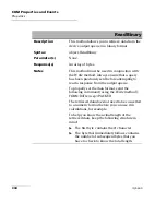
Страница 306: ...decimal The presence of data in all fields is mandatory If either field 3 or 4 is not available the ASCII character 0 shall be returned for that field A field may contain any 7 bit ASCII encoded bytes...

Страница 307: ...in the Standard Event Status Register to the TRUE logic 1 state when the instrument completes all pending operations Detection of the Operation Complete message can be accomplished by continuous poll...

Страница 308: ...er 1 into its Output Queue when the device completes all pending operations A consequence of this action is that the MAV bit in the Status Byte Register is set to state 1 Syntax OPC Parameter s None R...

Страница 309: ...e b Forces the device into OCIS state Operation complete Command Idle State c Forces the device into OQIS state Operation complete Query Idle State The Reset command explicitly DOES NOT affect the fol...

Страница 310: ...to enable the bits in the Status Byte Register Syntax SRE wsp RegisterValue Parameter s RegisterValue The program data syntax for RegisterValue is defined as a DECIMAL NUMERIC PROGRAM DATA element The...

Страница 311: ...below A bit value of zero shall indicate a disabled condition Example s SRE 52 where 52 bit ESB bit MAV and bit EAV See Also SRE STB SRE Bit Weight Meaning N U 128 Not used N U 64 Not used ESB 32 Even...

Страница 312: ...t Enable Register See the contents of this register below Syntax SRE Parameter s None Response Syntax RegisterValue ESB MSB N U N U N U N U MAV EAV LSB Status Request EnableRegister N U Bit Weight Mea...

Страница 313: ...alue The response data syntax for RegisterValue is defined as a NR1 NUMERIC RESPONSE DATA element The RegisterValue ranges from 0 through 255 When converted to binary base 2 the RegisterValue represen...

Страница 314: ...ds STB Description The STB query allows the programmer to read the status byte and Master Summary Status bit See the content of this register below Syntax STB Parameter s None Response Syntax Register...

Страница 315: ...erValue value expressed in base 2 binary represents the bit values of the Status Byte Register See the contents of this register below Example s STB Return 68 where 68 bit MSS and bit EAV See Also SRE...

Страница 316: ...red to their values prior to the TST Syntax TST Parameter s None Response Syntax Result Response s Result The response data syntax for Result is defined as a NR1 NUMERIC RESPONSE DATA element The Resu...

Страница 317: ...on System 309 IEEE 488 2 Required Commands WAI Description The WAI command shall prevent the device from executing any further commands or queries until the no operation pending flag becomes TRUE Synt...

Страница 318: ...e below contains a summary of the IQS 600 Integrated Qualification System specific commands These commands are fully explained on the following pages Command Parameter s P FORMat DATA ASCii PACKed Len...

Страница 319: ...data is transferred in a DEFINITE BLOCK RESPONSE DATA The ASCii type data is automatically identified by its syntax Therefore in these cases the FORMat subsystem is only necessary to determine the out...

Страница 320: ...rogram data syntax for Length is defined as a DECIMAL NUMERIC PROGRAM DATA element When ASCii data format is selected the optional Length parameter specifies the number of significant digits to be ret...

Страница 321: ...gth Response s Type The response data syntax for Type is defined as a CHARACTER RESPONSE DATA element The ASCII Type is returned when numeric data is transferred to ASCII bytes in NR1 NUMERIC RESPONSE...

Страница 322: ...umber of significant digits to be returned A Length value of zero indicates that the device selects the number of significant digits to be returned When the data is returned in PACKED Type the Length...

Страница 323: ...instruments are defined a single null STRING RESPONSE DATA is returned This is not affected by a RST command Syntax INSTrument CATalog Parameter s None Response Syntax Catalog Response s Catalog The...

Страница 324: ...If no logical instrument is defined a null STRING RESPONSE DATA value followed by a zero is returned This is not affected by a RST command Syntax INSTrument CATalog FULL Parameter s None Response Synt...

Страница 325: ...a syntax for Year is defined as a DECIMAL NUMERIC PROGRAM DATA element The Year is rounded to the nearest integer Its range is limited by the capability of the device The year shall be entered as a fo...

Страница 326: ...GRAM DATA element The Day is rounded to the nearest integer It ranges from 1 to the number of days in the month from the previous parameter This command keeps track of the number of days in each month...

Страница 327: ...ted Qualification System 319 Specific Commands SYSTem DATE Description The SYSTem DATE query returns the instrument s internal calendar This is not affected by a RST command Syntax SYSTem DATE Paramet...

Страница 328: ...NUMERIC RESPONSE DATA element The Month ranges from 1 to 12 inclusively The number 1 corresponds to January 2 to February and so on Day The response data syntax for Day is defined as a NR1 NUMERIC RES...

Страница 329: ...SYSTem ERRor NEXT Parameter s None Response Syntax Code Description Info Response s Code The response data syntax for Code is defined as a NR1 NUMERIC RESPONSE DATA element The Code is a unique integ...

Страница 330: ...ed to the info separated by a semi colon using the following format Date wsp Time where Date Year Month Day Time Hour Minute Second 24 hour time The maximum length of Description Info is 255 character...

Страница 331: ...ntax SYSTem TIME wsp Hour Minute Sec onds Parameter s Hour The program data syntax for Hour is defined as a DECIMAL NUMERIC PROGRAM DATA element The Hour is always rounded to the nearest integer It ra...

Страница 332: ...nd is rounded to the resolution of the clock It ranges from 0 to 60 A value of 60 is allowed since rounding may cause a number greater than 59 5 to be rounded to 60 When this element is rounded to 60...

Страница 333: ...25 Specific Commands SYSTem TIME Description This device has an internal clock and implements the SYSTem DATE query to get the clock time over the interface This is not affected by a RST command Synta...

Страница 334: ...ts returns hour information in 24 hour format Minute The response data syntax for Minute is defined as a NR1 NUMERIC RESPONSE DATA element The Minute ranges from 0 to 59 Second The response data synta...

Страница 335: ...sociated RST state Syntax SYSTem VERSion Parameter s None Response Syntax Version Response s Version The response data syntax for Version is defined as a NR2 NUMERIC RESPONSE DATA element The Version...

Страница 336: ......

Страница 337: ...operability In order to interoperate components developed in different languages must adhere to a binary structure specified by Microsoft OLE and ActiveX are based on COM Also programming languages su...

Страница 338: ...events available These properties and events are fully explained in the following pages ICSCPIAccess ICSCPIActiveX dll Object acting as an entry point Write property WriteBinary property Read propert...

Страница 339: ...ngle command or compound of commands to the device input buffer Syntax object Write Message Parameter s Message Required A string value corresponding to the program message to be sent Possible error s...

Страница 340: ...ram message to be sent Notes Use this method instead of the Write method if you need to send commands in binary COM is UNICODE Possible error s Timeout This error occurs if the operation could not be...

Страница 341: ...set the data format send the following command using the Write method FORM DATA wsp ASCII number_of_digits where number_of_digits corresponds to the number of digits after the decimal point that you...

Страница 342: ...ly sent before attempting to read a response from the output queue To properly set the data format send the following command using the Write method FORM DATA wsp PACKED The retrieved data does not ne...

Страница 343: ...error s Timeout This error occurs if the allowed delay has expired before the preceding Write operation could send a response to the output queue For information on timeout setting see Initialize on p...

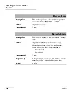
Страница 344: ...arameter s None RemoteState Description This property returns or sets the device s remote state Syntax object RemoteState to retrieve the state object RemoteState State to set the state State a Boolea...

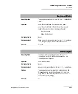
Страница 345: ...Response s If the property is used to get the device s lockout state the property returns a Boolean value Access Get Set StatusByte Description This read only property returns the device s status byt...

Страница 346: ...configure the different registers SRE ESE as stated in the IEEE 488 2 standard to receive SRQ When used in conjunction with StatusByte property see StatusByte on page 337 this event allows you to dete...

Страница 347: ...n the Telnet protocol All Windows versions include the Telnet client and the Telnet server components With these components you can create a remote command console session on a remote computer Command...

Страница 348: ...ix can use the freely available Telnet components to connect to the service A client can connect to multiple modules at a time A user can connect to multiple modules through single multiple sessions A...

Страница 349: ...sponse to IcExecutive and to TCP IP over Telnet accordingly To activate TCP IP over Telnet 1 Access the Instrument Control Configuration utility On an IQS 600 From IQS Manager click the Utilities func...

Страница 350: ...puter to the Telnet server in this case the IQS or FTB unit To execute a single SCPI command you can type or paste the command directly in the Telnet editor window To execute multiple SCPI commands sc...

Страница 351: ...puter start Windows 2 On the taskbar click Start Start button under Windows 8 1 and select Run 3 In the Open box type telnet and then click OK Note If you receive an error message it probably means th...

Страница 352: ...Service Example open 10 192 2 45 5024 Note Port 5024 is designated for sending SCPI commands in the Telnet protocol 5 Press ENTER to establish a connection with the Service Once the connection is est...

Страница 353: ...ipt file enclose them in a BEGIN and END block in the Telnet editor window and then press ENTER For more information see Internal Commands of the TCP IP over Telnet Protocol on page 349 Note Multiple...

Страница 354: ...esktop and then click Open Terminal The command prompt is displayed in the Telnet editor window 2 Connect to the TCP IP Telnet Service by typing the OPEN IP_ADDRESS_OF_TELNET_SERVER PORT command Examp...

Страница 355: ...e them in a BEGIN and END block in the Telnet editor window and then press ENTER For more information see Internal Commands of the TCP IP over Telnet Protocol on page 349 Note Multiple commands that a...

Страница 356: ...ase it A module is released by one of the following actions Executing the CLOSE LINS command to disconnect the link with the module For more information see CLOSE LINS on page 352 Executing the CLOSE...

Страница 357: ...nal commands are not case sensitive By default log files are generated both for client and server all logs are kept on your unit You can delete them with the CLEAR LOGS command see CLEAR LOGS on page...

Страница 358: ...IN and END To execute multiple SCPI commands you must enclose them in BEGIN and END blocks in a Telnet editor window Note To execute a single command simply type or paste the command in the Telnet edi...

Страница 359: ...og files that are older than 36 hours default value from the time you execute the command Note You can also delete the logs manually via the file explorer The client and sever logs are kept respective...

Страница 360: ...ber identifying the module for which you want to close the connections This command allows to close active connections You can send this command to close all client s connections with any module inclu...

Страница 361: ...a single session If the command is not executed successfully the possible reasons could be The module is already connected to a different client session The module is not present at the specified posi...

Страница 362: ...tains the specified connection LINS This means it will terminate all active connections that belongs to a session To know the status of the modules before terminating connections using the KILL LINS c...

Страница 363: ...mple Only the information of the remaining connected client is displayed STATUS CLIENT Syntax STATUS CLIENT This command lists out all clients with their connection time and modules STATUS CONNECTION...

Страница 364: ...ds of the TCP IP over Telnet Protocol STATUS MODULE Syntax STATUS MODULE This command lists out all the modules with the slot numbers where they are located WHO M I Syntax WHO M I This command retriev...

Страница 365: ...controller unit or IQS 610E HS expansion unit The IQS 9600 Utility Module is used to house non electrical elements only no electrical connections are provided The IQS 9600 Utility Module comes in eit...

Страница 366: ...Using the IQS 9600 Utility Module 358 IQS 600...

Страница 367: ...Using the IQS 9600 Utility Module Integrated Qualification System 359...

Страница 368: ......

Страница 369: ...ion 125 126 B back panel 4 6 7 backlight button 10 level 69 backup 12 benchtop putting units on 21 books SCPI and IEEE 488 2 187 boot first 39 braces 189 brackets angled 189 square 188 bumpers platfor...

Страница 370: ...programming 187 190 193 conventions safety 13 cooling fans clearance space 22 copying commands into text document 210 212 covers unit 17 creating integrated data display 104 current modules 99 current...

Страница 371: ...ptimizing performance 139 output units and formats 140 port 138 restrictions 136 selecting 143 H handshake rate 140 hard drive activity LED 10 RAID 1 12 hardware customizing 95 help see online user gu...

Страница 372: ...ents 242 list separator 189 live backup 12 loading configuration 93 local control 127 143 local to remote 178 locating units 107 lock LED 10 lockout status 176 177 logging off Windows 55 M main power...

Страница 373: ...grating 357 passwords in IQS Manager 85 PDF files viewing 106 PDF see online user guide peripheral connectors 4 6 data related 5 pipe character 189 platform bumpers 23 commands 311 legs 23 port Ethern...

Страница 374: ...e 30 34 repairing unit 17 reset settings 97 results working on 103 return merchandise authorization RMA 247 returned values setting 140 reverting to default settings 97 145 right swipe 41 rights in IQ...

Страница 375: ...ecting 84 status local 176 local with lockout 176 remote 176 remote with lockout 177 switching 178 status bar 100 status byte register STB 183 storage requirements 213 SumatraPDF reader 106 swipe 41 s...

Страница 376: ...ration in different units 92 utilities in IQS Manager 108 in Windows 108 utility module 357 V ventilation 17 90 vertical bar 189 viewing PDF files 106 system information 239 volume adjusting 68 W WAN...

Страница 377: ...363 2006 X Indicates that this toxic or hazardous substance contained in at least one of the homogeneous materials used for this part is above the limit requirement in SJ T11363 2006 SJ T11363 2006 Pa...

Страница 378: ...MARKING REQUIREMENTS Product Environmental protection use period years Logo This E 2 product EXFO 10 Batterya a a If applicable 5...

Страница 379: ...EXFO ASIA PACIFIC 62 Ubi Road 1 09 01 02 Oxley Bizhub 2 SINGAPORE 408734 Tel 65 6333 8241 Fax 65 6333 8242 EXFO CHINA Beijing Global Trade Center Tower C Room 1207 36 North Third Ring Road East Dongch...

Отзывы: