background image


Rectifying faults 

Resetting JOBs (welding tasks) to the factory settings 


099-0M37XM-EW501 

16.07.2018


31


Error 

(Err) 

Category 

Possible cause 

Remedy 

a) 

b)  c) 

59 

Machine incompatible 

Check machine usage 

60 

Software update required 

Inform Service. 


Categories legend (resetting the error) 

a)  The error message will disappear once the error has been rectified. 

b)  The error message can be reset by pressing a push-button: 

Welding machine control 

Push-button 

RC1 / RC2 


Expert 


Expert 2.0 / Expert XQ 2.0 


CarExpert / Progress (M3.11) 


alpha Q / Concept / Basic / Basic S / Synergic / 
Synergic S / Progress (M3.71) / Picomig 355 

not possible 

c)  The error message can only be reset by switching the machine off and on again. 

The shielding gas error (Err 6) can be reset by pressing the "Welding parameters" key button. 


6.3 

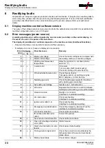
Resetting JOBs (welding tasks) to the factory settings 


All customised welding parameters that are stored will be replaced by the factory settings. 


6.3.1 

Resetting a single JOB 


Figure 6-1 


6.3.2 

Resetting all JOBs 


JOBs 1

–128 and 170–256 will be reset. 

Custom JOBs 129

–169 are maintained. 

Содержание M3.7X-M

Страница 1: ...Operating instructions EN Control Synergic M3 7X M 099 0M37XM EW501 Observe additional system documents 16 07 2018 ...

Страница 2: ...authorised sales partners can be found at www ewm group com en specialist dealers Liability relating to the operation of this equipment is restricted solely to the function of the equipment No other form of liability regardless of type shall be accepted This exclusion of liability shall be deemed accepted by the user on commissioning the equipment The manufacturer is unable to monitor whether or n...

Страница 3: ...return 14 5 2 MIG MAG welding 15 5 2 1 Welding task selection 15 5 2 1 1 Basic welding parameters 15 5 2 1 2 Operating mode 15 5 2 1 3 Welding power operating point 16 5 2 1 4 Accessory components for operating point setting 16 5 2 1 5 Arc length 16 5 2 1 6 Arc dynamics choke effect 17 5 2 2 Expert menu MIG MAG 17 5 2 2 1 Burn back 18 5 2 3 Program sequence 18 5 2 4 Operating modes functional sequ...

Страница 4: ...0 6 1 Display machine control software version 30 6 2 Error messages power source 30 6 3 Resetting JOBs welding tasks to the factory settings 31 6 3 1 Resetting a single JOB 31 6 3 2 Resetting all JOBs 31 7 Appendix A 33 7 1 JOB List 33 8 Appendix B 34 8 1 Parameter overview setting ranges 34 8 1 1 MIG MAG welding 34 8 1 2 MMA welding 34 9 Appendix C 35 9 1 Searching for a dealer 35 ...

Страница 5: ...ing or operating procedures which must be closely observed to prevent possible minor personal injury The safety information includes the CAUTION keyword in its heading with a general warning symbol The risk is explained using a symbol on the edge of the page Technical aspects which the user must observe to avoid material or equipment damage Instructions and lists detailing step by step actions for...

Страница 6: ...on These operating instructions are part of the complete documentation and valid only in combination with all other parts of these instructions Read and observe the operating instructions for all system components especially the safety instructions The illustration shows a general example of a welding system Figure 2 1 Item Documentation A 1 Wire feeder A 2 Conversion instructions A 3 Power source...

Страница 7: ...cepted for any damages arising from improper usage The equipment must only be used in line with its designated purpose and by trained or expert personnel Do not improperly modify or convert the equipment 3 1 Use and operation solely with the following machines This description may only be applied to machines with the M3 7X M machine control 3 2 Documents which also apply Operating instructions for...

Страница 8: ...control sections For description purposes the machine control has been divided into two sections A B to ensure maximum clarity The setting ranges for the parameter values are summarised in the parameter overview section see 8 1 chapter Figure 4 1 Item Symbol Description 0 1 Control section A see 4 1 1 chapter 2 Control section B see 4 1 2 chapter ...

Страница 9: ... power see 4 3 2 chapter Setting various parameters values depending on the preselection The white signal lights LED around the rotary knob light up when setting is possible 3 Operating mode selection push button Non latched Latched Special latched 4 Display of arc dynamics The height and orientation of the set arc dynamics are displayed 5 Correction of arc length click wheel Setting the arc lengt...

Страница 10: ...l system via special parameters P29 see 5 4 chapter 3 Material thickness signal light Indication of the selected material thickness 4 Welding current signal light Display of the welding current in amperes 5 Signal light Wire speed Lights when the wire speed is shown on the display 6 Lock function signal light Use display left lock function push button to switch on and off 7 Correction voltage arc ...

Страница 11: ...lay To the left of the parameter displays there is the parameter selection push button It is used to select the welding parameters to be displayed and their values Each time one the button is clicked the display proceeds to the next parameter signal lights indicate the selection After reaching the last parameter the system is restarted with the first one Figure 4 4 MIG MAG Parameter Nominal values...

Страница 12: ...ettings in the different machine menus 4 3 3 Setting advanced welding parameters Expert menu The Expert menu contains functions and parameters which cannot be set directly in the machine control or which do not need to be et on a regular basis The number and display of these parameters depends on the previously selected welding procedure or the functions To select them hold the welding power click...

Страница 13: ...ntity for the application on the pressure regulator Setting instructions Welding process Recommended shielding gas quantity MAG welding Wire diameter x 11 5 l min MIG brazing Wire diameter x 11 5 l min MIG welding aluminium Wire diameter x 13 5 l min 100 argon TIG Gas nozzle diameter in mm corresponds to l min gas throughput Helium rich gas mixtures require a higher gas volume The table below can ...

Страница 14: ...el The operating elements are installed under the protective cap of wire feed mechanism Figure 5 3 5 1 2 Wire return The wire return function is used to retract the wire electrode without tension and protection gas By simultaneously pressing and holding the wire inching and gas test buttons the wire return speed increases in a ramp function special parameter P1 see 5 4 1 1 chapter from 1 m min to ...

Страница 15: ...mics if necessary 5 2 1 1 Basic welding parameters The user must first determine the basic parameters material type wire diameter and shielding gas type of the welding system These basic parameters are then compared with the welding job list JOB LIST The combination of the basic parameters gives a JOB number which must now be entered on the control unit This basic setting must be rechecked or adju...

Страница 16: ... this welding voltage see 5 2 1 5 chapter Figure 5 7 5 2 1 4 Accessory components for operating point setting The operating point can be set at various accessory components as well such as remote control special welding torches or robot and industrial bus interfaces optional interface for automated welding required not available for all machines of this series See the operating instructions for th...

Страница 17: ...addition the selected settings are displayed with signal lights below the rotary knobs Figure 5 9 5 2 2 Expert menu MIG MAG The Expert menu has adjustable parameters stored that don t require regular setting The number of parameters shown may be limited e g if a function is deactivated A B A B A A A A A A B B B B B B Figure 5 10 Display Setting selection Ignition current Setting range in percent d...

Страница 18: ...he adjustable value stands for the time until the power source switches off the welding current after the welding process has been stopped Welding wire behaviour Setting instructions Wire electrode is sticking in the weld pool Increase value Wire electrode is sticking on the contact tip or large ball formation on the wire electrode Reduce value 5 2 3 Program sequence Certain materials require spec...

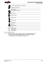
Страница 19: ...ed Wire creep Wire burn back Gas pre flow Gas post flow Non latched Latched Special latched t Time PSTART Start program PA Main program PEND End program 5 2 4 2 Automatic cut out The welding machine ends the ignition process or the welding process with an ignition fault no welding current flows within 5 s after the start signal arc interruption arc is intrerrupted for longer than 5 s ...

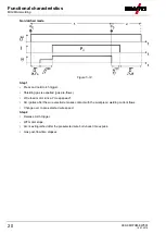
Страница 20: ...elding gas is expelled gas pre flows Wire feed motor runs at creep speed Arc ignites after the wire electrode makes contact with the workpiece welding current flows Change over to pre selected wire speed Step 2 Release torch trigger WF motor stops Arc is extinguished after the preselected wire burn back time expires Gas post flow time elapses ...

Страница 21: ...motor runs at creep speed Arc ignites after the wire electrode makes contact with the workpiece welding current flows Change over to pre selected WF speed main program PA Step 2 Release torch trigger no effect Step 3 Press torch trigger no effect Step 4 Release torch trigger WF motor stops Arc is extinguished after the preselected wire burn back time expires Gas post flow time elapses ...

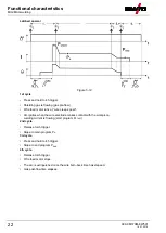
Страница 22: ...t wire creep speed Arc ignites when the wire electrode makes contact with the workpiece welding current is flowing start program PSTART 2nd cycle Release torch trigger Slope to main program PA 3rd cycle Press and hold torch trigger Slope to end program PEND 4th cycle Release torch trigger Wire feed motor stops The arc is extinguished once the wire burn back time has elapsed Gas post flow time elap...

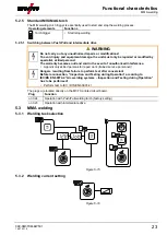
Страница 23: ...rranty becomes null and void in the event of unauthorised interference Appoint only skilled persons for repair work trained service personnel Dangers resulting from failure to perform test after conversion Before reconnection Inspection and Testing during Operation according to IEC BS EN 60974 4 Arc welding systems Inspection and Testing during Operation has to be performed Perform test to IEC DIN...

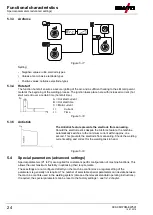
Страница 24: ...ealing Should the electrode stick despite the Arcforce feature the machine automatically switches to the minimum current within approx one second This prevents the electrode from annealing Check the welding current setting and correct for the welding task in hand Figure 5 19 5 4 Special parameters advanced settings Special parameters P1 to Pn are applied for customer specific configuration of mach...

Страница 25: ...x works HOLD function 0 HOLD values are not displayed 1 HOLD values are displayed Ex works Correction or nominal voltage display 0 Correction voltage display ex works 1 Absolute nominal voltage display Unit system see 5 4 1 5 chapter 0 metric system ex works 1 Imperial system 5 4 1 1 Ramp time for wire inching P1 The wire inching starts with a speed 1 0 m min for 2 secs It is subsequently increase...

Страница 26: ...n values for the last main program parameters used for welding are displayed Hold function not active P15 0 Setpoint values for the main program parameters are displayed 5 4 1 4 Correction or nominal voltage display P24 When setting the arc correction using the right hand rotary knob the display will either show the correction voltage 9 9 V ex works or the absolute nominal voltage 5 4 1 5 Units sy...

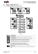
Страница 27: ...0 mΩ 8 mΩ ex works Lead resistance 2 Lead resistance for the second welding circuit 0 mΩ 60 mΩ 8 mΩ ex works Only qualified service personnel may change the parameters Only qualified service personnel may change the parameters Time based power saving mode see 5 5 3 chapter Time to activation of the power saving mode in case of inactivity Setting disabled or numerical value 5 60 min ex works 20 Ser...

Страница 28: ...earth cable length of 5 m an intermediate hose package length of 1 5 m and a water cooled welding torch length of 3 m A welding voltage correction is therefore required to optimise the welding properties for other hose package lengths By realigning the cable resistance the voltage correction value can be set close to zero again The electric cable resistance should be realigned whenever an accessor...

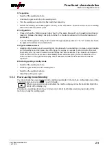
Страница 29: ...e contact tip on a clean purged location on the workpiece and then press the torch trigger for approx 2 seconds A short circuit current will flow briefly which is used to determine and display the cable resistance The value can be between 0 mΩ and 40 mΩ The new value is immediately saved without requiring further confirmation If no value is shown on the right hand display then measurement failed T...

Страница 30: ...rvoltage 3 x Welding machine excess temperature Allow the machine to cool down mains switch to 1 4 x x Coolant error Fill coolant Turn on pump shaft coolant pump Check air cooling unit overcurrent trip 5 x Wire feeder tachometer error Check the wire feeder Tachogenerator is not emitting a signal M3 51 defective inform Service 6 x Shielding gas error Check shielding gas supply for machines with shi...

Страница 31: ...ntrol Push button RC1 RC2 Expert Expert 2 0 Expert XQ 2 0 CarExpert Progress M3 11 alpha Q Concept Basic Basic S Synergic Synergic S Progress M3 71 Picomig 355 not possible c The error message can only be reset by switching the machine off and on again The shielding gas error Err 6 can be reset by pressing the Welding parameters key button 6 3 Resetting JOBs welding tasks to the factory settings A...

Страница 32: ...Rectifying faults Resetting JOBs welding tasks to the factory settings 32 099 0M37XM EW501 16 07 2018 Figure 6 2 ...

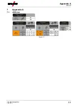
Страница 33: ...Appendix A JOB List 099 0M37XM EW501 16 07 2018 33 7 Appendix A 7 1 JOB List Figure 7 1 ...

Страница 34: ...PSTART 1 V 9 9 9 9 Slope time of start program PSTART to main program PA 1 s 0 20 Slope time of main program PA to end program PEND 1 s 0 20 End crater current 1 0 200 Correction of arc length in end program PEND 1 V 9 9 9 9 Burn back time 1 0 333 Voltage correction 0 V 9 9 9 9 Wire feed speed absolute main program PA 1 m min 0 00 20 0 1 depending on the selected welding task JOB 8 1 2 MMA welding...

Страница 35: ...dix C Searching for a dealer 099 0M37XM EW501 16 07 2018 35 9 Appendix C 9 1 Searching for a dealer Sales service parteners www ewm group com en specialist dealers More than 400 EWM sales partners worldwide ...

Отзывы: