


Model 5601MSC
Model 5601MSC Master SPG/Master Clock System
OVERVIEW
Revision 2.2
Page - 7
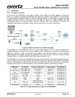
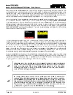
1.1.8. Configuring the Sync Outputs
The sync outputs of the 5601MSC are configured in the OUTPUT menu, accessed by pressing the
OUTPUT button. All sync outputs are derived from the master oscillator and will be locked in frequency
and phase. The sync outputs are all programmable to output several different sync types and can be
phased independently from each other.
The 10MHz and Wordclock outputs are additional sync outputs that can be programmed to output any
standard including black burst or HD tri-level. Likewise, Sync outputs 1 to 6 can be configured to output
10MHz or Wordclock. The BNC labels and matching default mode assignments for the 10MHz and
Wordclock outputs were chosen to ease migration from the older model 5600MSC.
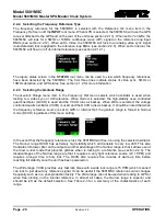
In the OUTPUT menu, the sync outputs are configured using the
SYNC 1
to
SYNC 6
sub-menus as
well as the 10MHz and Wordclock sub-menus. Each sync output can set to output any number of black
burst or HD tri-level standards. They are all phased independently. When configuring a sync output the
Mode must be selected first. By default, the mode of all sync outputs are set to NTSC-M black burst for
North American units, and PAL-B black burst for European units. Configure the Mode of each sync
output to the format desired for the installation.
There are numerous other configuration settings for each sync output, some may be disabled (dark
text) or enabled (white text) depending on the output mode selected. Scroll over each of the available
menu items and press the HELP button for more information on the function of each menu item. See
section 4.4.2 for more information on configuring the sync outputs.
1.1.9. Configuring the Test Generator Outputs
If the unit has been equipped with a test generator option, such as the
SDTG
,
HDTG
, or
3GTG
options,
then there will be several test generator outputs available. The video test generator outputs include two
composite analog video test generators that are configured in menus
ATG 1
and
ATG 2
. There are four
serial digital video test generators, each with two BNC outputs. These are configured in the
SDI TG 1
,
SDI TG 2
,
SDI TG 3
, and
SDI TG4
menus. All test generators are derived from the master oscillator
and will be automatically locked in frequency and phase. The test generators are independent from one
another and can be configured to different formats and different phase offsets. By default, all phases
will be aligned to the selected frequency reference.
There are also three AES outputs configured in the
AES Audio
sub-menu. AES 1 and AES 2 can
contain audio tones while the DARS output contains muted audio
. There are unbalanced (75Ω)
versions of these outputs available on
BNC connectors as well as balanced (110Ω) copies available on
the AUDIO terminal block.
Two channels of balanced analog audio (left and right) are configured in the
Analog Audio
sub-menu.
They can be configured to output steady tones, or beeps scheduled to occur at specific times during the
day. The analog audio outputs are available on the AUDIO removable terminal block connector.
The quickest and easiest way to discover how to configure the outputs is to scroll through the available
menu items and press the
HELP
button for a description of each menu item function.
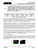
Many test patterns are built into the 5601MSC firmware, but additional test signals can be loaded from
the CompactFlash. The CompactFlash slot is located behind the front panel as shown below. To
access the CompactFlash card, the front panel must first be removed by loosening the two thumb
screws and pulling it off the front of the unit. This can all be done while the unit is powered on.
Содержание 5601MSC
Страница 2: ...This page left intentionally blank ...